

SIEMENS Automation System Part 1 of 3
E-Book PDF
Overview: Siemens Automation System Part 1 of 3
Contact Us for more information

SIEMENS Automation System Part 1 of 3
E-Book PDF
Overview: Siemens Automation System Part 1 of 3
Contact Us for more information

Overview: Siemens Substation Automation System Part 2 of 3 (DIGSI software)
Content: IEC 61850- Design a feeder, Configuration in DIGSI, Create an interlocking page, Goose Message-configuration in DIGSI, Import IEC61850 to PASFS

DIGSI 4.91 is Compatible with Windows 7, Windows 8, and Windows 10. Elec-Engg provides a comprehensive training course on DIGSI 4 and DIGSI 5.
DIGSI software Introduction, Part I
DIGSI Tutorial, Part II: Implementation of a simple function in a SIPROTEC relay with DIGSI

In a world where the number of people who need to learn about data communications and networking is exploding, Forouzan’s book is the answer. The book’s visual approach makes it easy for students to learn about and understand the concepts involved in this rapidly developing field.
TCP/IP Protocol Suite teaches students and professionals, with no prior knowledge of TCP/IP everything they need to know about the subject. This comprehensive book uses hundreds of figures to make technical concepts easy to grasp as well as many examples that help tie the material to the real world.
The fourth edition of TCP/IP Protocol Suite has been fully updated to include all of the recent technology changes in the field. Additionally, out-of-date material has been overhauled to reflect recent changes in technology.

SIEMENS Protection and Automation Manuals & Catalogs


IEC 61850-9-2 Process bus equipment
The AMU is a Merging Unit in a digital substation that can publish messages over the substation process bus in compliance with the IEC 61850-9-2LE or IEC61869-9 standard. Data is published in the form of sampled values (SV) that comply with the light edition (LE) of the IEC 61850-9-2. And it has high accuracy time synchronization via PPS or IRIG-B, NTP, PTP1588, local clock, or via its internal built-in GPS receiver. It Complies with: IEC 61850-9-2LE and IEC 61850 GOOSE messaging. Also complies with the new IEC 61869-9 standard.
Part I, Introduction:
DIGSI Tutorial Part II: Implementation of a simple function in a Siprotec relay with DIGSI
We welcome your questions, enhancement requests, improvement suggestions, criticisms, and any comments.
This File contains DIGSI 4.82, the PC program for configuring, parameterizing, starting, and operating all digital SIPROTEC protection, combination, and bay devices, in its current version 4.82. With a PC or a notebook, you can parameterize the devices via the interfaces and export and visualize the fault data.

VAMP 57 Relays Schneider Make,
VAMP Relays 50 Series Schneider Electric,
VAMP Relays 200 series Schneider Electric,
VAMP Relays 300 Series Schneider Electric,
SEPAM Relays 40 Series Schneider Electric,
SEPAM Relays 60 Series Schneider Electric,
SEPAM Relays 80 Series Schneider Electric
VAMP 57 Relays Schneider Make

VAMP Relays 50 Series Schneider Electric
VAMP Relays 200 series Schneider Electric
VAMP Relays 300 Series Schneider Electric
SEPAM Relays 40 Series Schneider Electric
SEPAM Relays 80 Series Schneider Electric
SEPAM Relays 10 Series Schneider Electric
SEPAM Relays 60 Series Schneider electric
SEPAM 80 catalog

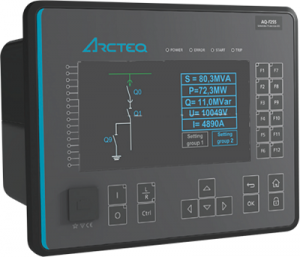
AQ-S255 bay control IED may be applied for demanding control applications. The AQ-S255 comes with full current, voltage, power, and energy measurement capability and may be equipped with additional I/O depending on application needs. Easy to use and powerful logic programming expands further the application range to more demanding control needs. Up to 11 optional I/O or communication cards can be inserted depending on application requirements. A large freely programmable HMI display provides a quick visualization of the object, alarm, and event status. The AQ-S255 communicates using various protocols including IEC 61850 substation communication standard.


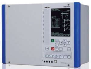
The GRD200 multi-function protection IED is designed to provide comprehensive protection and control applications for transmission lines and distribution feeders in all types of networks. Typical feeder protection such as multiple, high accuracy overcurrent protection elements with inverse time and definite time delay functions which can be independently subject to directional control, thermal overload, under/overvoltage, under/over frequency, circuit breaker failure, and voltage-controlled overcurrent protection can be provided. Among the model lineup, current-base, voltage-based or current, and voltage-base configurations can be selected.
Selection of HMI: Standard LCD, large LCD, or separate large LCD
24 configurable tri-state LEDs selectable red/ green/ yellow
7 programmable function keys for user demand operation
Personal computer interface (USB and Ethernet ports)
Monitoring jacks for internal circuit tests

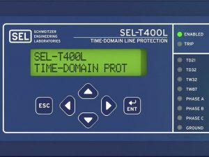
Built for speed, security, and simplicity.
Key Features
Ultra-High-Speed Fault-Clearing Times With Security Protect critical lines using the SEL-T400L with time-domain principles. The relay operates at ultra-high speeds without compromising security. The incremental quantity-based TD21 distance element can be set as far as 80 percent of the line length and operates in the order of 4 ms without communications. The POTT scheme with an incremental quantity-based TD32 directional element operates as fast as 2 ms, and the TW32 directional element operates as fast as 1 ms. The TW87 traveling-wave differential element operates in 1 to 4 ms, depending on the line length and fault location. The relay includes solid-state, trip-rated outputs. When used with a low-latency communications channel, the SEL-T400L trips breakers in the order of 4 to 6 ms for the vast majority of line faults.
Easy Settings and Deployment Use the SEL-T400L with existing control cables and wiring to connect to conventional current and voltage transformers, including CCVTs. The traveling wave differential (TW87) element uses current inputs for differential protection. The traveling wave directional (TW32) element can be used with CCVTs because it relies on stray capacitances for measuring the polarity of the first voltage wave. The incremental quantity elements (TD21 and TD32) use a lower-frequency spectrum and work well with any voltage or current transformer.
fast Mirrored Bits communications over direct fiber or a multiplexer for communications-assisted schemes. The TW87 differential element uses a dedicated 1 Gbps direct fiber channel for both communications and data alignment. None of the SEL-T400L protection elements require absolute time input, such as IRIG-B. Setting the SEL-T400L is simple and does not require complex short-circuit studies. It uses nameplate data that do not need to be reevaluated as the system evolves.
Time-domain line protection, SEL-T4287, T400l SEL, SELtraveling wave, SEL-T400l.
These include current and voltage transformer ratios, line impedances and length, TD21 reach, and port configuration settings.

This Relay coordination study and setting calculation, Which applies the selective system to clear only faulted feeder, is used to temporarily energize substation 133kV Switchgear and related incomings, bustie 33/6.3kV transformer feeders.
Format: PDF
Page: 370
Indian: Click here to buy (Rs 350) and download
Non-Indian Users: 11 $ (Click here to pay and download)
Similar Products:
Relay Coordination and setting for Substation (excel sheet + explanation)
")
This course is a combination of lectures, software packages, tutorial videos of the experiences in the lab. Become familiar with the DIGSI 4 software for configuring and setting SIPROTEC 4 relays with Windows-based MATRIX-driven software.
Learn also how to analyze grid fault events based on the data stored in the relay.
The training is intended for protective relay engineers, designers, and technicians from electric utilities and the industrial section interested in the programming, commissioning, maintenance, and operating of SIPROTEC4 protection devices.

DIGSI 4 Online Training Course

DIGSI 5 Online Training Course
This course will be held in your place.
More information Please Contact Us
Related product:

Click here to Download IEC 61850 Video training course (4 hours)
This course provides comprehensive coverage of IEC 61850 and will provide you with the tools and knowledge to tackle your next digital substation project with confidence.
Practical exercises will include the following:
This course will be held in your place.
Click here to Download IEC 61850 Video training course (4 hours)

| [1] | 00-SEPAM Protection Principles. | |
| [2] | 01-Plan_Network structures. | |
| [3] | 02-Plan_Network and machine faults. | |
| [4] | 2V73 Setting Guide High Impedance Differential Relay. | |
| [5] | 03-Plan_Source of Isc. | |
| [6] | 04-Plan_Symmetrical components. | |
| [7] | 05-Plan_Calculation of Isc. | |
| [8] | 06-Plan_Calculation of Isc_exercises. | |
| [9] | 7PG17 – XR Intertripping, Interposing, Supervision, and Special Purpose Relays. | |
| [10] | 7PG21 – Solkor R/Rf Pilot Wire Current Differential Protection. | |
| [11] | 7PJ15 – Trip Relay High-Speed Tripping. | |
| [12] | 07-Plan_Earthing systems. | |
| [13] | 7SA. | |
| [14] | 7SG18 Solkor N Current Differential Protection. | |
| [15] | 7SG23 – MSCDN Capacitor Bank Protection. | |
| [16] | 7SG26 – Tau Autoreclose and synchronization. | |
| [17] | 7SG26 Auto re-close. | |
| [18] | 7SG117 Argus 7 Synchronising Relay. | |
| [19] | 7SR10 Argus Overcurrent and Earth Fault Relay. | |
| [20] | 7SR11 and 7SR12 Argus Overcurrent Relays. | |
| [21] | 7SR11 and 7SR12 Argus Overcurrent Relays. | |
| [22] | 7SR17 Rho Motor Protection Relay. | |
| [23] | 7SR23 DAD High Impedance Protection Relay. | |
| [24] | 7SR45 Argus Self-Powered Overcurrent and Earth Fault Relay. | |
| [25] | 7SR157 Argus Check and System Synchronising Relays. | |
| [26] | 7SR158 Argus Voltage and Frequency Relays. | |
| [27] | 7SR191 Capa Capacitor Bank Protection Relay. | |
| [28] | 7SR210 & 7SR220 Argus Overcurrent Protection Relay. | |
| [29] | 7SR224 Argus Recloser Controller. | |
| [30] | 7SR224 Argus Recloser Controller. | |
| [31] | 7SR242 Duobias Transformer Protection Relay. | |
| [32] | 08-Plan_Earthing systems_exercises. | |
| [33] | 09-Plan_CTs. | |
| [34] | 10-Plan_CTs_exercises. | |
| [35] | 11-Plan_Irsd measurement. | |
| [36] | 12-Plan_LPCT. | |
| [37] | 13-Plan_VTs. | |
| [38] | 14-Plan_Vrsd measurement. | |
| [39] | 15-Plan_Prot funct general charact. | |
| [40] | 16-Plan_IDMT curves_exercises. | |
| [41] | 17-Plan_Discrimination. | |
| [42] | 18-Plan_ANSI 67. | |
| [43] | 19-Plan_ANSI 67N. | |
| [44] | 20-Plan_Differential_87. | |
| [45] | 21-Plan_ANSI 87M. | |
| [46] | 22-Plan_ANSI 87T. | |
| [47] | 23-Plan_ANSI 64REF. | |
| [48] | 24-Plan_ANSI 49RMS. | |
| [49] | 25-Plan_Network protection. | |
| [50] | 26-Plan_Busbar protection. | |
| [51] | 27-Plan_Transformer protection. | |
| [52] | 28-Plan_ANSI 24_transformer. | |
| [53] | 29-Plan_ANSI 26-63. | |
| [54] | 30-Plan_Motor protection. | |
| [55] | 31-Plan_ANSI 40_motor. | |
| [56] | 32-Plan_ANSI 78PS_motor. | |
| [57] | 33-Plan_Synchronous generator protection. | |
| [58] | 34-Plan_ANSI 21B. | |
| [59] | 35-Plan_ANSI 24_generator. | |
| [60] | 36-Plan_ANSI 40_generator. | |
| [61] | 37-Plan_ANSI 50-27. | |
| [62] | 38-Plan_ANSI 64G. | |
| [63] | 39-Plan_ANSI 78PS_generator. | |
| [64] | 40-Plan_Capacitor protection. | |
| [65] | 100% stator earth fault protection: ANSI 64G. | |
| [66] | 100% stator ground fault protection – a comparison of two protection methods. | |
| [67] | 269 Motor Management Relay Instruction Manual. | |
| [68] | 369 Motor Management Relay Instruction Manual. | |
| [69] | 369 Motor Management Relay QuickStart Guide. | |
| [70] | 469 Motor Management Relay Instruction Manual. | |
| [71] | 469 Motor Management Relay INSTRUCTION MANUAL. | |
| [72] | 469 MOTOR MANAGEMENT RELAY® Instruction Manual. | |
| [73] | 489 GENERATOR MANAGEMENT RELAY® Instruction Manual. | |
| [74] | 615 series ANSI IEC 61850 Engineering Guide. | |
| [75] | 615 series ANSI Technical Manual. | |
| [76] | 650 series IEC 61850 Communication Protocol Manual. | |
| [77] | 670 series 2.0 ANSI DNP3 Communication Protocol Manual. | |
| [78] | 670 series 2.0 IEC Engineering Manual. | |
| [79] | 670 series 2.0 IEC IEC 60870-5-103 Communication Protocol Manual. | |
| [80] | 670 series 2.0 IEC IEC 61850 Edition 1 Communication Protocol Manual. | |
| [81] | 670 series 2.0 IEC IEC 61850 Edition 2 Communication Protocol Manual. | |
| [82] | 670 series 2.0 IEC LON Communication Protocol Manual. | |
| [83] | 670 series 2.0 IEC Operation Manual. | |
| [84] | 670 series 2.0 IEC SPA Communication Protocol Manual. | |
| [85] | 670 series Engineering Manual. | |
| [86] | 670 series IEC 2.0 Cyber Security Deployment Guideline. | |
| [87] | 745 TRANSFORMER MANAGEMENT RELAY INSTRUCTION MANUAL. | |
| [88] | 750/760 Feeder Management Relay® Instruction Manual. | |
| [89] | 800 question. | |
| [90] | 2013 IEC 61850 INTEROPERABILITY TEST Munich, Germany. | |
| [91] | 2015Protection, monitoring, and control solutions using Wide Area Monitoring Systems. | |
| [92] | 61400-25-2 Wind turbines – Part 25-2: Communications for monitoring and control of wind power plants – Information models. | |
| [93] | 61850-1. | |
| [94] | 61850-2. | |
| [95] | 61850-3. | |
| [96] | 61850-4. | |
| [97] | 61850-7-1{ed1.0}. | |
| [98] | 61850-9-1{ed1.0}en. | |
| [99] | 61850-9-2{ed1.0}en. | |
| [100] | 61850-90-1. | |
| [101] | 61850-90-5. | |
| [102] | 61850-90-7. | |
| [103] | 61850-90-7. | |
| [104] | 61850 easy. | |
| [105] | ABB AFS660 Switch High-availability Ethernet device based on new IEC-standard redundancy protocols PRP/HSR. | |
| [106] | ABB is implementing the first commercial installation of IEC 61850-9-2 LE process-bus technology. | |
| [107] | ABB Power and Automation: Solid Foundations for Smart Cities. | |
| [108] | ABB PROTECTION APPLICATION HANDBOOK. | |
| [109] | ABB review Special Report IEC 61850. | |
| [110] | ABB S.p.A. PPD U.O. Adda – HV PASS Family & new products. | |
| [111] | ABB technologies that changed the world. | |
| [112] | ABB wind power solutions Total solutions for wind power plants. | |
| [113] | AC_A_en_670_series_Ver.1.2__IEC_symbols. | |
| [114] | Acceptance, Commissioning, and Field Testing for Protection and Automation Systems. | |
| [115] | ACSELERATOR Diagram Builder User’s Guide. | |
| [116] | ACSELERATOR QuickSet SEL-5030 Software Instruction Manual. | |
| [117] | ACSELERATOR RTAC® SEL-5033 Software Instruction Manual. | |
| [118] | Active Management of Distributed Energy Resources Using Standardized Communications and Modern Information Technologies. | |
| [119] | Adapting Electricity Networks to a Sustainable Energy System – Smart metering and smart grids. | |
| [120] | ADAPTIVE DISTANCE RELAY SETTING FOR TRANSMISSION LINES IN THE PRESENCE OF UPFC AND WIND FARMS. | |
| [121] | Adaptive Protection and Microgrid Control Design for Hailuoto Island. | |
| [122] | Advanced protection and control IEDs from ABB. | |
| [123] | ADVANCED TAP-CHANGER CONTROL TO COUNTERACT POWER SYSTEM VOLTAGE INSTABILITY. | |
| [124] | AE_en_670_series_ver._2.0__IEC_symbols. | |
| [125] | AGILE DIGITAL SUBSTATIONS 2.0. | |
| [126] | AGILE DIGITAL SUBSTATIONS The complete guide. | |
| [127] | Air-Insulated Medium-Voltage Switchgear NXAIR, up to 24 kV. | |
| [128] | Alborz Distribution Network Planning Long-term planning. | |
| [129] | Alpha – Electromechanical Relays. | |
| [130] | Alpha – Electromechanical Relays. | |
| [131] | ALPS Advanced Line Protection System Instruction Manual. | |
| [132] | ALSTOM RELAY PRODUCT RANGE. | |
| [133] | American National Standard Dictionary of Electromagnetic Compatibility (EMC) including Electromagnetic Environmental Effects (E3). | |
| [134] | Analysis and implementation of the IEC 61850 standard. | |
| [135] | Analysis and Simulation of Electrical and Computer Systems. | |
| [136] | Anomaly Checks for Relay Settings. | |
| [137] | ANSI code protection. | |
| [138] | Application Considerations of IEC 61850/UCA 2 for Substation Ethernet Local Area Network Communication for Protection and Control. | |
| [139] | Application Examples Communication set-up for RED 670 Differential protection and 670 series binary transfer in telecommunication networks. | |
| [140] | Application guide for calculation of short-circuit currents in low-voltage radial systems. | |
| [141] | Application Guide for the choice of protective relays. | |
| [142] | Application Manual Connecting the worlds of building construction and power distribution. | |
| [143] | Application Models for Power Distribution Data Centres. | |
| [144] | APPLICATION NOTE AQ 2xx Relay Output Guideline. | |
| [145] | Application Note Extending existing PTL items for distance protection with power swing blocking and tripping tests. | |
| [146] | Application Note High current relay testing. | |
| [147] | Application Note Power Transformer Vector Group and Turns Ratio Testing with CMC 256plus/356. | |
| [148] | Application Note Rogowski current sensor simulation with a CMC Test Set. | |
| [149] | Application Note Testing 6-phase Synchronizers with two CMC Test Sets. | |
| [150] | Application Note Testing a relay’s power swing impedance characteristic with Advance Distance Module. | |
| [151] | Application Note Testing transducers with multiple outputs. | |
| [152] | Application Note Using a Single CMC Test Set for Testing Six-Phase Synchronizing Relays. | |
| [153] | Application Note Using the Relay Setting Import Filter for SEL Relays. | |
| [154] | Application of an IEC 61850 and Synchrophasor Solution for Electricity of Vietnam. | |
| [155] | Application of Overreaching Distance Relays. | |
| [156] | Application of Overreaching Distance Relays. | |
| [157] | Application of Unit Protection Schemes for AutoTransformers. | |
| [158] | APPLICATIONS OF A REAL-TIME DIGITAL SIMULATOR IN POWER-SYSTEM EDUCATION AND RESEARCH. | |
| [159] | Applications of IEC 61850 Standard to Protection Schemes. | |
| [160] | Applications of Phasor Measurement Units. | |
| [161] | Applications of PMU measurements in the Belgian electrical grid. | |
| [162] | The Application-View Model of the International Standard IEC 61850. | |
| [163] | Applying IEC 61850 to Real Life: Modernization Project for 30 Electrical Substations. | |
| [164] | Applying Radio Communication in Distribution Generation Teleprotection Schemes. | |
| [165] | AQ-200 series protection, control, measurement, and monitoring IEDs. | |
| [166] | Arc Fault Monitoring System. | |
| [167] | Arc Protection Relay REA 101. | |
| [168] | The art and science of protective relaying. | |
| [169] | AS-Interface. | |
| [170] | Asynchronous motor protection. | |
| [171] | Auto Re-close and Sync Check. | |
| [172] | Automated Analysis of power system events. | |
| [173] | Automated Test Solutions for Agile Protection Relays. | |
| [174] | Automatic Testing of Relays in R&D at ABB Sweden. | |
| [175] | Auxiliary Relay (7PJ111, 7PJ112, 7PJ113) and Trip Relay (7PJ121) Better protection and more efficiency for your power system. | |
| [176] | Basic Application and Simulation Testing of a High-Speed Motor Bus Transfer System. | |
| [177] | BASIC PRINCIPLES OF DISTANCE PROTECTION DEVICES1. | |
| [178] | Basics of Current and Voltage Transformers. | |
| [179] | Battery fundamental. | |
| [180] | Bay control REC670 Pre-configured Product Guide. | |
| [181] | Bay control REC670 Relion® 670 series Ver. 1.2. | |
| [182] | The Building Blocks of a Data-Aware Transport Network: Deploying Viable Ethernet and Virtual Wire Services via Multiservice ADMs. | |
| [183] | bus bar protection 1. | |
| [184] | Busbar Differential Protection / 7SS52 SIPROTEC 4 7SS52 distributed numerical busbar and breaker failure protection. | |
| [185] | Busbar Differential Protection / 7SS60 SIPROTEC 7SS60 centralized numerical busbar protection. | |
| [186] | CABLE LIST. | |
| [187] | CABLE TRAY LADDER LAYOUT WITH INSTRUMENT LOCATION IF ANY. | |
| [188] | Cahier technique no. 192 Protection of MV/LV substation transformers. | |
| [189] | Cahier technique no. 211 The protection of LV motors. | |
| [190] | CALCULATING LOADABILITY LIMITS OF DISTANCE RELAYS. | |
| [191] | Calculation of Relay Setting of P543 for Majalgon S.S.K. | |
| [192] | Calculations for LV and HV networks. | |
| [193] | Calibration System for Electronic Instrument Transformers With Digital Output. | |
| [194] | A Calibration System for Instrument Transformers with Digital Output. | |
| [195] | Capacitor Protection Relay SPAJ 160 C Product Guide | |
| [196] | CASE STUDIES RELATED TO OVERHEAD TRANSMISSION-LINE SYSTEM DISTURBANCES. | |
| [197] | Case Study: Design and Implementation of IEC 61850 From Multiple Vendors at CFE La Venta II. | |
| [198] | Case Study: Introduction of New Technologies in Unattended Substations in Panama. | |
| [199] | Case Study: Using IEC 61850 Methods for RTU Replacement and Distributed Automation. | |
| [200] | CB Simulation Application Note. | |
| [201] | CENTRALISED BUSBAR PROTECTION FOR SMARTER GRIDS. | |
| [202] | Centralized and Distributed Active and Reactive Power Control of a Utility Connected Microgrid Using IEC61850. | |
| [203] | Challenges and Integration of PV and Wind Energy Facilities from a Smart Grid Point of View. | |
| [204] | Challenges and Lessons Learned from Commissioning an IEC 61850-90-5 Based Synchrophasor System. | |
| [205] | Challenges in Protection of a Series-Compensated 400 kV Double Line. | |
| [206] | chapter AC motors starting and protection systems. | |
| [207] | Characteristics of Elements. | |
| [208] | Circuit Breaker Monitoring Using the SEL-421 Relay. | |
| [209] | Circuit-Breaker Switchgear Type 8BT2 up to 36 kV, 31.5 kA, Air-Insulated. | |
| [210] | Circuit-Breaker Switchgear Type SIMOPRIME, up to 17.5 kV, Air-Insulated. | |
| [211] | A closer look at accuracy Reliable harmonic assessment by measuring voltage transformer accuracy. | |
| [212] | CMC 256. | |
| [213] | CMC 256plus Reference Manual. | |
| [214] | CMC 353 Reference Manual. | |
| [215] | CMEngine. | |
| [216] | CMGPS. | |
| [217] | Commissioning Instructions For use with Substation and Telecontrol Batteries BA300 Battery Alarm. | |
| [218] | Commissioning of a Distributed Busbar Protection Using a System-Oriented Test in the Field. | |
| [219] | COMMON REQUIREMENTS FOR ELECTRIC POWER EQUIPMENT. | |
| [220] | Communication in Power application. | |
| [221] | Communication Networks Communication solutions for mission-critical applications. | |
| [222] | Communication set-up for Relion 670-series 2.0 using PCM600 2.6 or later Setting and application guide. | |
| [223] | Communications network solutions for smart grids. | |
| [224] | Communications-Assisted Schemes for Distributed Generation Protection. | |
| [225] | Comparison of the operational speed of hard-wired and IEC 61850 standard-based implementations of a reverse blocking protection scheme. | |
| [226] | Comparisons process-to-bay level peer-to-peer network delay in IEC61850 substation communication systems. | |
| [227] | Complete Sepam Presentation_EN_2009. | |
| [228] | A Comprehensive Investigation of Wireless LAN for IEC 61850–Based Smart Distribution Substation Applications. | |
| [229] | Comprehensive testing of motor protection systems and Testing practice in the petrochemical industry. | |
| [230] | Comprehensive Testing of Synchronous Generator Protection Systems and AVR Reaction. | |
| [231] | Comprehensive Testing of Synchronous Generator Protection Systems and AVR Reaction. | |
| [232] | COMPUTER RELAYING FOR POWER SYSTEMS. | |
| [233] | Concept. | |
| [234] | The concept of IEC 61850. | |
| [235] | Configuration and Performance of IEC 61850 for First-Time Users – UNC Charlotte Senior Design Project. | |
| [236] | Connecting the SEL-849 Motor Management Relay to EtherNet/IP™ Networks. | |
| [237] | Connection of AC500 to an IEC60870-5-101 (Serial) Master via ProCon164. | |
| [238] | CONSTRUCTION OF 220 KV GAS-INSULATED SUBSTATIONS (GIS) SECTOR-20 GURGAON ON TURNKEY BASIS AGAINST TENDER ENQUIRY NO. JICA-011. | |
| [239] | CONTROL BOARD SPECIFICATION & DETAILS. | |
| [240] | Control of district heat substations Reliable and energy-efficient. | |
| [241] | CONTROL SYSTEM. | |
| [242] | Control your CMC test set with your tablet PC and the new CMControl P App. | |
| [243] | Coordination Analysis and Relay Setting Tool. | |
| [244] | Coordination Analysis and Relay Setting Tool. | |
| [245] | Coordination of Overcurrent Relays for Industrial Radial System. | |
| [246] | COSI-NXCT F3 Flexible Optical Current Transformer. | |
| [247] | Cost-Efficient Solution for Power Distribution. | |
| [248] | CPOL Polarity Checher. | |
| [249] | Creating Nonvolatile Counters in SELOGIC® Control Equations. | |
| [250] | CT Saturation in Industrial Applications – Analysis and Application Guidelines. | |
| [251] | Current and Energy Measurement Technology. | |
| [252] | CURRENT TRANSFORMER PERFORMANCE ANALYSIS. | |
| [253] | CURRENT TRANSFORMERS. | |
| [254] | Current Transformers Ratio / Polarity / Types. | |
| [255] | Current-Sense Transformer Application Design Guidelines. | |
| [256] | Current-Transformer Phase-Shift Compensation and Calibration. | |
| [257] | D30 Line Distance Relay Instruction Manual D30 revision: 5.2x. | |
| [258] | D60 Line Distance relay Setting Example. | |
| [259] | Data transport network. | |
| [260] | DBF Digital Breaker Failure Protection Instruction Manual GEK-106168F | |
| [261] | DCCB AND DELTA I RELAY SETTING CALCULATION METHOD. | |
| [262] | DCS in Substation | |
| [263] | Dealing with Packet Delay Variation in IEEE 1588 Synchronization Using a Sample-Mode Filter. | |
| [264] | Defining and Designing Communications Determinism for Substation Applications. | |
| [265] | Design & Commissioning of a Distributed IEC 61850 Communication Based Protection Scheme for a Railway Electrification Project. | |
| [266] | Design and Implementation of Packet Analyzer for IEC 61850 Communication Networks in Smart Grid. | |
| [267] | Design and Performance Testing of a Multivendor IEC61850–9-2 Process Bus Based Protection Scheme. | |
| [268] | Design of 132/33KV Substation. | |
| [269] | The design of a modern protection system for a Static Var Compensator. | |
| [270] | Design of a Priority-Based Load Shed Scheme and Operation Tests. | |
| [271] | Design, Development, and Commissioning of a Substation Automation Laboratory to Enhance Learning. | |
| [272] | Design, Development, and Commissioning of a Substation Automation Laboratory to Enhance Learning. | |
| [273] | Design, Development, and Commissioning of a Supervisory Control and Data Acquisition (SCADA) Laboratory for Research and Training. | |
| [274] | Design, Modeling, and Evaluation of Protective Relays for Power Systems. | |
| [275] | Designing next generation’s protection systems. | |
| [276] | DETAILED CONNECTION (WIRING) DIAGRAM AND PART LIST OF COMMON PANEL. | |
| [277] | Detecting Power System Islanding With Time Error Measurement. | |
| [278] | Determining the Faulted Phase. | |
| [279] | DEVELOPING PROTECTIVE RELAY FACEPLATES. | |
| [280] | Development of IEC61850 Based Substation Engineering Tools with IEC61850 Schema Library. | |
| [281] | Development of laboratory exercises based on OPNET Modeler. | |
| [282] | DGP Digital Generator Protection Relay™ Instruction Manual. | |
| [283] | Differential (87) Element Settings. | |
| [284] | Differential Protection. | |
| [285] | Differential Protection 7UT6x | |
| [286] | Differential protection for shunt reactors and power transformers – similarities and differences. | |
| [287] | Differential Protection RET 54_/Diff6T function Application and Setting Guide. | |
| [288] | Digital Protection for Power Systems. | |
| [289] | Digital Substation Solutions. | |
| [290] | Digital umspannwerk. | |
| [291] | Digitalization in Transmission and Distribution. | |
| [292] | DIGSI 4 Start-Up Manual. | |
| [293] | DIGSI 5 Software Description V07.00 Help. | |
| [294] | Direct Evaluation of IEC 61850-9-2 Process Bus Network Performance. | |
| [295] | Directional Earth Fault Relay Operation in Mutually Coupled Multiple Circuit Distribution Lines. | |
| [296] | Directional Overcurrent Relaying (67) Concepts. | |
| [297] | Distance. | |
| [298] | Distance Protection 7SA6. | |
| [299] | Distance Protection 7SA6 SIPROTEC 4 7SA6 distance protection relay for all voltage levels. | |
| [300] | Distance Protection 7SA522 SIPROTEC 4 7SA522 distance protection relay for transmission lines. | |
| [301] | Distance Protection for transmission lines: part 1. | |
| [302] | Distance Protection for transmission lines: part 2. | |
| [303] | Distance Protection in Distribution Systems: How It Assists With Integrating Distributed Resources. | |
| [304] | Distance Protection OHL Setting Example. | |
| [305] | Distance Protection Power Swing. | |
| [306] | Distance Protection: Earth-Faults and Fault Resistance. | |
| [307] | Distance Protection: Earth-Faults in Isolated and Resonant grounded Systems. | |
| [308] | Distance Protection: Monitoring Functions. | |
| [309] | Distance Protection: Negative Sequence Direction Measurement. | |
| [310] | Distance Protection: Series Compensated Lines. | |
| [311] | Distance Protection: Tele-Protection and weak indeed. | |
| [312] | Distance Relay Element Design. | |
| [313] | Distance Relays. | |
| [314] | Distance Relays 101 30th Annual Hands-On Relay School March 2013. | |
| [315] | Distributed busbar protection REB500 including line and transformer protection Product Guide. | |
| [316] | Distributed energy resources present new challenges for protection systems and the way they are tested. | |
| [317] | Distributed Multifunction Fault Recorder. | |
| [318] | A Distributed PMU for Electrical Substations With Wireless Redundant Process Bus. Download: contact Us | |
| [319] | Distribution Automation Handbook Section 3 Elements of power distribution systems. | |
| [320] | Distribution Automation Handbook Section 8.1 Electrical Safety. | |
| [321] | Distribution Automation Handbook Section 8.2 Relay Coordination. | |
| [322] | Distribution Automation Handbook Section 8.2 Relay Coordination. | |
| [323] | Distribution Automation Handbook Section 8.5 MV Feeder Short-circuit Protection. | |
| [324] | Distribution Automation Handbook Section 8.6 MV Feeder Earth-fault Protection. | |
| [325] | Distribution Automation Handbook Section 8.7 Protection of HV Transformers. | |
| [326] | Distribution Automation Handbook Section 8.10 Protection of Capacitor Banks. | |
| [327] | Distribution Automation Handbook Section 8.11 Motor Protection. | |
| [328] | Distribution Automation Handbook Section 8.13 Backup Protection. | |
| [329] | Distribution Automation Handbook Section 8.14 Automatic Reclosing. | |
| [330] | Distribution Automation Handbook Section 8.15 Impedance-based Fault Location. | |
| [331] | Distribution Grid Automation Raising the bar in grid efficiency and reliability. | |
| [332] | Distribution Switchgear. | |
| [333] | Dr. Vladimir Gurevich. | |
| [334] | Draft Trial-Use Recommended Practice for Grounding of Direct Current Equipment Enclosures in Traction Power Distribution Facilities. | |
| [335] | DRAWING PACKAGE FOR 1CP001 PANEL. | |
| [336] | DRAWING PACKAGE FOR 2CP001. | |
| [337] | DRAWING PACKAGE FOR 2CP002. | |
| [338] | DRAWING PACKAGE FOR 2CP003. | |
| [339] | DRAWING PACKAGE FOR 3CP002. | |
| [340] | DRAWING PACKAGE FOR 3CP003. | |
| [341] | DRAWING PACKAGE FOR 4CP001. | |
| [342] | DRAWING PACKAGE FOR 4CP002. | |
| [343] | DRAWING PACKAGE FOR 4CP003. | |
| [344] | DRAWING PACKAGE FOR 5C. | |
| [345] | Duplicate and Circulating Frames Discard Methods for PRP and HSR (IEC62439-3). | |
| [346] | Dynamic Testing of an IEC 61850 Based 110 kV Smart Substation Solution. | |
| [347] | Early Detection of Power System Oscillations for Improved Stability Assessment. | |
| [348] | earth fault relay with recorder guide. | |
| [349] | Earth Fault protection. | |
| [350] | EARTHING CONNECTIONS POINTS DRAWING. | |
| [351] | Easy and Intuitive Method for Testing Transformer Differential Relays. | |
| [352] | ECT Evaluation by an Error Measurement System According to IEC 60044-8 and 61850-9-2. | |
| [353] | ECT Evaluation by an Error Measurement System According to IEC 60044-8 and 61850-9-2. | |
| [354] | Eduard Muljadi, https://www.nrel.gov/research/eduard-muljadi.html. | |
| [355] | The Effects of Waveform Distortion on Power Protection Relays. | |
| [356] | Efficient Energy Automation with the IEC 61850 Standard Application Examples Energy Automation. | |
| [357] | Efficient network integration of renewable energy resources on the distribution level. | |
| [358] | Electrical components for the railway industry. | |
| [359] | Electrical installation guide According to IEC International Standards. | |
| [360] | Electrical installation handbook Protection, control, and electrical devices. | |
| [361] | Electrical Integration with System 800xA. | |
| [362] | Electrical Machines Mathematical Fundamentals of Machine Topologies. | |
| [363] | ELECTRICAL POWER FACILITIES SYSTEM AND EQUIPMENT PROTECTIVE RELAYING. | |
| [364] | Electrical Power Systems by D. Das (2006). | |
| [365] | Electrical Protection. | |
| [366] | Electrical Transmission and Distribution Reference Boo. | |
| [367] | Electricity and Electronics Fundamentals, 2nd Ed. by Dale R. Patrick, Stephen W. Fardo (2008). | |
| [368] | Emerging Applications of Synchronous Ethernet in Telecommunication Networks. | |
| [369] | Enabling digital substations. | |
| [370] | Energy Management of Internet Data Centers in Smart Grid. | |
| [371] | EnerLyzer. | |
| [372] | ENGINE CONTROL SYSTEM DETAIL MANUAL. | |
| [373] | Engineering Perspective on IEC 61850. | |
| [374] | The Engineering Application of Jianfeng Smart Substation based on Integration of Power Secondary Systems. | |
| [375] | Enter the network of expertise. | |
| [376] | Ergon_appendix_f_proposed_substation_Design_A. | |
| [377] | ERL 61850 IED Configurator. | |
| [378] | ETAP_ComparisonResults. | |
| [379] | Ethernet & IEC 61850 Concepts, Implementation, Commissioning. | |
| [380] | Ethernet in SAS. | |
| [381] | Ethernet in Substation Automation Applications – Issues and Requirements. | |
| [382] | Ethernet Module EN100 for IEC 61850 with electrical/optical 100 MBit Interface Application Examples. | |
| [383] | Ethernet Networks Redundancy With Focus On IEC 61850 Applications. | |
| [384] | ETHERNET NETWORKS REDUNDANCY WITH FOCUS ON IEC 61850 APPLICATIONS. | |
| [385] | Ethernet-Based Public Communication Services: Challenge and Opportunity. | |
| [386] | ETM/V1/CT-R0-03-2017. | |
| [387] | Evaluation of IEC 61850-9-2 Samples Loss on Total Vector Error of an Estimated Phasor. | |
| [388] | Evaluation of Time Gateways for Synchronization of Substation Automation Systems. | |
| [389] | An Example Distance Protection Application with Complicating Factors. | |
| [390] | An Example Distance Protection Application with Complicating Factors. | |
| [391] | Executive Summary (Introduction to MMS. | |
| [392] | Experience with Multiterminal Line Differential Protection Installed on Series Compensated, 400 kV Line with FiveEnds. | |
| [393] | F650 Digital Bay Controller Instruction manual GEK-106310T. | |
| [394] | F650 Digital Bay Controller User manual GEK-113000T. | |
| [395] | Fast substation busbar protection with IEC 61850 and GOOSE. | |
| [396] | Fault Current Distribution Across Special Transformers. | |
| [397] | A Fault Location Technique for Two-Terminal Multisection Compound Transmission Lines Using Synchronized Phasor Measurements. | |
| [398] | Fault locator with 2 ended measurement. | |
| [399] | FAULTS AND PROTECTION OF ELECTRIC ENERGY SYSTEMS. | |
| [400] | Feeder Protection and Control REF615 Application Manual. | |
| [401] | Feeder Protection Relay REF610. | |
| [402] | Feeder Terminal REF 54_. | |
| [403] | Fiber OpticsCurrentSensor –Free Standing Enabling smart grids and digital substations. | |
| [404] | Fieldbus_Mahe. | |
| [405] | Focus on the application – IEC 61850 experience with the third-party system configuration tool. | |
| [406] | Frequency of Calibration of OMICRON CMC Test Equipment. | |
| [407] | Frequency Response Characteristic of MV Voltage Transformers and their Accurate Measurement up to 2.5/3 kHz. | |
| [408] | A Fresh Look at Limits to the Sensitivity of Line Protection. | |
| [409] | From IEC 61850-Compliant SEL Device CID File Configuration to Network Optimization: A Job Done® Example. | |
| [410] | Fundamentals and Improvements for Directional Relays. | |
| [411] | Fundamentals Of Differential Protection. | |
| [412] | Fundamentals of-Directional Overcurrent & Earth Fault Protection. | |
| [413] | G30 Generator Management Relay UR Series Instruction Manual. | |
| [414] | G60 Generator Management Relay UR Series Instruction Manual. | |
| [415] | Gas Insulated Switchgear Concept Design for Service Continuity in GIS. | |
| [416] | GE motor protection. | |
| [417] | General Guideline. | |
| [418] | GENERAL INDUSTRY SAFETY INSTRUCTIONS OF GEN-SET. | |
| [419] | General Training Electrical Protection. | |
| [420] | General Training Electrical Protection. | |
| [421] | Generator Black Start Validation Using Synchronized Phasor Measurement. | |
| [422] | GENERATOR PROTECTION. | |
| [423] | Generator Protection. | |
| [424] | Generator Protection / 7RW600 SIPROTEC 7RW600 numerical voltage, frequency and overexcitation protection relay. | |
| [425] | Generator Protection / 7UM61 SIPROTEC 4 7UM61 multifunction generator and motor protection relay. | |
| [426] | Generator Protection / 7UM62 SIPROTEC 4 7UM62 multifunction generator, motor and transformer protection relay. | |
| [427] | Generator Protection / 7VE6 SIPROTEC 7VE6 multifunction paralleling device 11/. | |
| [428] | Generator Protection Application Guide. | |
| [429] | Generator Protection Setting Criteria. | |
| [430] | Generator Protection, Relay Setting Calculations. | |
| [431] | GENERATOR TERMINAL BOX DRAWING. | |
| [432] | Generic IEC61850 IED Connectivity Package User‘s Guide. | |
| [433] | Get on the digital bus to SA. | |
| [434] | Getting Started IPC@CHIP Embedded Web Controller Family IEC 61850 Basics. | |
| [435] | Go Rugged. With Siemens!. | |
| [436] | GOOSE AIR. | |
| [437] | GOOSE-based Protection Scheme Implementation & Testing in Laboratory. | |
| [438] | GOOSE Configuration Example. | |
| [439] | GOOSE Configuration Example Testing an IEC 61850-Compliant Relay with a CMC Test Set, the GOOSE Configuration
Module and IEDScout 4.00. | |
| [440] | GOOSE Message-Based Multi Substation Overload Shedding (OLS) Scheme using Ethernet over Internet Protocol (EoIP) Tunnelling. | |
| [441] | Goose Messaging Determining its potential in a real case. | |
| [442] | GOOSE Timing Measurements in an IEC 61850 Substation – Using a Distributed Hybrid Signal Analyzer. | |
| [443] | GPS and IEEE 1588 synchronization for the measurement of synchrophasors in electric power systems. | |
| [444] | Green Electricity – 25 Green Technologies That Will Electrify Your Future by Kendall Haven (2011). | |
| [445] | Grid Automation REC615 and RER615 IEC 61850 Engineering Guide. | |
| [446] | Grid Connectivity Standards, Grid standards. | |
| [447] | Ground Fault Protection. | |
| [448] | GSSE Configuration Example. | |
| [449] | Guide to Power System Selective Coordination 600V and Below. | |
| [450] | HardFiber. | |
| [451] | High Reliability with ABB Disconnector. | |
| [452] | High-Speed Busbar Protection with GOOSE. | |
| [453] | High-voltage switchgear and control gear – Part 111: Automatic circuit reclosers and fault interrupters for alternating current systems up to 38 kV. | |
| [454] | History and Test Method of Protection Relay with Rogowski Coil Based Current Transformer. | |
| [455] | How network simulation improves protection testing and eases the application of end-to-end testing. | |
| [456] | How to enable SNTP on a CMC Test Set. | |
| [457] | How Would We Know?. | |
| [458] | HV Substation Design: Applications and Considerations. | |
| [459] | HV SUBSTATION PROJECT. | |
| [460] | iec61850-5{ed1.0}. | |
| [461] | iec61850-6{ed1.0}. | |
| [462] | iec61850-6{ed2.0}. | |
| [463] | IEC61850-7-2. | |
| [464] | iec61850-7-2{ed2.0}. | |
| [465] | IEC61850-7-3. | |
| [466] | iec61850-7-4{ed1.0}. | |
| [467] | iec61850-7-420{ed1.0}. | |
| [468] | iec61850-8-1{ed1.0}. | |
| [469] | iec61850-8-1{ed1.0}en-2004. | |
| [470] | iec61850-8-1{ed2.0}. | |
| [471] | iec61850-9-2{ed2.0}. | |
| [472] | iec61850-9-2{ed2.0}. | |
| [473] | IEC61850-9-2LE. | |
| [474] | iec61850-90-5{ed1.0}en. | |
| [475] | iec61850-90-7{ed1.0}. | |
| [476] | IEC61850 Based Process Bus Protection Solution for Remote Located Power Transformers. | |
| [477] | IEC61850 Modeling for Switch Management. | |
| [478] | IEC 60076-21 Power transformers – Part 21: Standard requirements, terminology, and test code for step-voltage regulators. | |
| [479] | IEC 60255-24 Measuring relays and protection equipment – Part 24: Common format for transient data exchange (COMTRADE) for power systems. | |
| [480] | IEC 60870-5-101/104 Slave Technical. | |
| [481] | IEC 60870-5-103 Communication Protocol Manual. | |
| [482] | IEC 60870-5-104. | |
| [483] | IEC 60909. | |
| [484] | IEC 61346-2 Industrial systems, installations and equipment, and industrial products – Structuring principles and reference designations – Part 2: Classification of objects and codes for classes. | |
| [485] | IEC 61400-12 Wind turbine generator systems – Part 12: Wind turbine power performance testing. | |
| [486] | IEC 61850-3 and IEEE 1588. | |
| [487] | IEC 61850-8-1-2004. | |
| [488] | IEC 61850-9-2 Based Process Bus. | |
| [489] | IEC 61850-9-2 Process Bus Communication Interface for Light Weight Merging Unit Testing Environment. | |
| [490] | IEC 61850-10. | |
| [491] | IEC 61850 – What It Can and Cannot Offer to Traditional Protection Schemes. | |
| [492] | IEC 61850: COMMUNICATION NETWORKS AND SYSTEMS IN SUBSTATIONS. | |
| [493] | IEC 61850 Based Breaker Failure Protection Scheme Design for TNB Double Busbar Substation. | |
| [494] | IEC 61850 -Communication Networks and Systems in Substations: An Overview of Computer Science. | |
| [495] | IEC 61850 driver FAQ. | |
| [496] | IEC 61850 Enabled Automatic Bus Transfer Scheme for Primary Distribution Substations. | |
| [497] | IEC 61850 General. | |
| [498] | IEC 61850 GOOSE and IEEE C37.118 Synchrophasors Used for Wide-Area Monitoring and Control, SPS, RAS, and Load and Generation Management. | |
| [499] | IEC 61850 Goose applications to distribution protection schemes. | |
| [500] | IEC 61850 in the oil and gas industries. | |
| [501] | IEC 61850 interoperability. | |
| [502] | IEC 61850 MMS Client Driver Help. | |
| [503] | IEC 61850 MMS SCADA Network Optimization for IEDs. | |
| [504] | IEC 61850 Model Expansion Toward Distributed Fault Localization, Isolation, and Supply Restoration. | |
| [505] | IEC 61850 Part 7-420 DER Logical Nodes Final Draft International Standard (FDIS). | |
| [506] | IEC 61850 Process Bus – It is Real!. | |
| [507] | IEC 61850 Protection Testing Versatile tools for working with IEC 61850 devices. | |
| [508] | IEC 61850 standard for SA. | |
| [509] | The IEC 61850 standard for SA. | |
| [510] | IEC 61850 Substation Configuration Language and Its Impact on the Engineering of Distribution Substation Systems. | |
| [511] | IEC 61850 System Configurator. | |
| [512] | IEC 61850 Technical Overview. | |
| [513] | IEC 61850 TRAINING PROGRAM. | |
| [514] | IEC 61850/61400 Model Designer. | |
| [515] | IEC 61850: Role of Conformance Testing in Successful Integration. | |
| [516] | IEC 61850: WHAT YOU NEED TO KNOW ABOUT FUNCTIONALITY AND PRACTICAL IMPLEMENTATION. | |
| [517] | IEC 61850-Based Feeder Terminal Unit Modeling and Mapping to IEC 60870-5-104. | |
| [518] | IEC 61850-Based Information Model and Configuration Description of Communication Network in Substation Automation. | |
| [519] | IEC 62357: TC57 Architecture Part 1: Reference Architecture for Power System Information Exchange. | |
| [520] | IEC 62439 PRP: Bumpless Recovery for Highly Available, Hard Real-Time Industrial Networks. | |
| [521] | IED Configuration Guidelines. | |
| [522] | IEDs interoperability, interchangeability, and logical nodes compatibility. | |
| [523] | IEEE-1588 Standard for a Precision Clock Synchronization Protocol for Networked Measurement and Control Systems. | |
| [524] | IEEE 802.1AS and IEEE 1588. | |
| [525] | IEEE 802.3ba 40 and100 Gigabit Ethernet Architecture. | |
| [526] | IEEE 1588. | |
| [527] | IEEE 1588 Precision Time Protocol Time Synchronization Performance. | |
| [528] | IEEE 1588 Precision Time Synchronization Solution for Electric Utilities. | |
| [529] | IEEE 1588 Version 2. | |
| [530] | IEEE Application Guide for IEEE Std 1547™, IEEE Standard for Interconnecting Distributed Resources with Electric Power
Systems. | |
| [531] | IEEE Guide for AC Motor Protection. | |
| [532] | IEEE Guide for AC Motor Protection. | |
| [533] | IEEE Guide for Application of Digital Line Current Differential Relays Using Digital Communication. | |
| [534] | IEEE Guide for Automatic Reclosing of Circuit Breakers for AC Distribution and Transmission Lines. | |
| [535] | IEEE Guide for Breaker Failure Protection of Power Circuit Breakers. | |
| [536] | IEEE Guide for Determining Fault Location on AC Transmission and Distribution Lines. | |
| [537] | IEEE Guide for Determining Fault Location on AC Transmission and Distribution Lines. | |
| [538] | IEEE Guide for Diagnostic Field Testing of Fluid-Filled Power Transformers, Regulators, and Reactors. | |
| [539] | IEEE Guide for Differential and Polarizing Relay Circuit Testing. | |
| [540] | IEEE Guide for Field Testing of Relaying Current Transformers. | |
| [541] | IEEE Guide for Field Testing of Relaying Current Transformers. | |
| [542] | IEEE Guide for Field Testing of Relaying Current Transformers. | |
| [543] | IEEE Guide for Gas-Insulated Substations Rated Above 52 kV Sponsored by the Substations Committee IEEE 3. | |
| [544] | IEEE Guide for Generating Station Grounding. | |
| [545] | IEEE Guide for Grounding of Instrument Transformer Secondary Circuits and Cases. | |
| [546] | IEEE Guide for Identifying and Improving Voltage Quality in Power Systems. | |
| [547] | IEEE Guide for Improving the Lightning Performance of Electric Power Overhead Distribution Lines. | |
| [548] | IEEE Guide for Moisture Measurement and Control in SF6 Gas-Insulated Equipment. | |
| [549] | IEEE Guide for Monitoring, Information Exchange, and Control of Distributed Resources Interconnected with Electric Power Systems. | |
| [550] | IEEE Guide for On-Site Acceptance Tests of Electrical Equipment and System Commissioning of 1000 kV AC and Above. | |
| [551] | IEEE Guide for Paralleling Regulating Transformers. | |
| [552] | IEEE Guide for Phasor Data Concentrator Requirements for Power System Protection, Control, and Monitoring. | |
| [553] | IEEE Guide for Phasor Data Concentrator Requirements for Power System Protection, Control, and Monitoring. | |
| [554] | IEEE Guide for Power System Protection Testing. | |
| [555] | IEEE Guide for Power System Protective Relay Applications of Audio Tones Over Voice Grade Channels. | |
| [556] | IEEE Guide for Power System Protective Relay Applications Over Digital Communication Channels. | |
| [557] | IEEE Guide for Protective Relay Application to Transmission-Line Series Capacitor Banks. | |
| [558] | IEEE Guide for Protective Relay Application to Transmission-Line Series Capacitor Banks. | |
| [559] | IEEE Guide for Protective Relay Applications to Distribution Lines. | |
| [560] | IEEE Guide for Protective Relay Applications to Power System Buses. | |
| [561] | IEEE Guide for Protective Relay Applications to Power Transformers. | |
| [562] | IEEE Guide for Protective Relaying of Utility-Consumer Interconnections. | |
| [563] | IEEE Guide for Sulphur Hexafluoride (SF6) Gas Handling for High-Voltage (over 1000 Vac) Equipment. | |
| [564] | IEEE Guide for Switchgear—Unit Substation—Requirements. | |
| [565] | IEEE Guide for Switchgear—Unit Substation—Requirements. | |
| [566] | IEEE Guide for Synchronization, Calibration, Testing, and Installation of Phasor Measurement Units (PMUs) for Power System Protection and Control. | |
| [567] | IEEE Guide for Temporary Protective Grounding Systems Used in Substations. | |
| [568] | IEEE Guide for the Application of Capacitance Current Switching for AC High-Voltage Circuit Breakers Above 1000 V. | |
| [569] | IEEE Guide for the Application of Current Transformers Used for Protective Relaying Purposes Corrigendum 1: corrections to Equation 18 and Equation 19. | |
| [570] | IEEE Guide for the Application of Current Transformers Used for Protective Relaying Purposes Corrigendum 1: Corrections to Equation 18 and Equation 19. | |
| [571] | IEEE Guide for the Application of Gas-Insulated Substations 1 kV to 52 kV. | |
| [572] | IEEE Guide for the Application of Neutral Grounding in Electrical Utility Systems, Part IV—Distribution. | |
| [573] | IEEE Guide for the Application of Neutral Grounding in Electrical Utility Systems—Part I: Introduction. | |
| [574] | IEEE Guide for the Application of Protective Relays Used for Abnormal Frequency Load Shedding and Restoration. | |
| [575] | IEEE Guide for the Application of Rogowski Coils Used for Protective Relaying Purposes. | |
| [576] | IEEE Guide for the Application of shunt reactor switching. | |
| [577] | IEEE Guide for the Application of Thyristor Surge Protective Device Components. | |
| [578] | IEEE Guide for the Design and Installation of Cable Systems in Substations. | |
| [579] | IEEE Guide for the Functional Specification of Fixed-Series Capacitor Banks for Transmission System Applications. | |
| [580] | IEEE Guide for the Interpretation of Gases Generated in Oil-Immersed Transformers. | |
| [581] | IEEE Guide for the Protection of Communication Installations from Lightning Effects. | |
| [582] | IEEE Guide for the Protection of Shunt Capacitor Banks. | |
| [583] | IEEE Guide for Transformer Loss Measurement. | |
| [584] | IEEE Guide for Transformer Loss Measurement. | |
| [585] | IEEE Guide to Describe the Occurrence and Mitigation of Switching Transients Induced by Transformers, Switching The device, and System Interaction. | |
| [586] | IEEE Recommended Practice for Calculating Short – Circuit Currents in Industrial and Commercial Power Systems. | |
| [587] | IEEE Recommended Practice for Establishing Liquid-Filled and Dry- Type Power and Distribution Transformer Capability When Supplying Nonsinusoidal Load Currents. | |
| [588] | IEEE Recommended Practice for Grounding of Industrial and Commercial Power Systems. | |
| [589] | IEEE Recommended Practice for Monitoring Electric Power Quality. | |
| [590] | IEEE Recommended Practice for Network Communication in Electric Power Substations. | |
| [591] | IEEE Recommended Practice for Overvoltage and Insulation Coordination of Transmission Systems at 1000 kV AC and Above. | |
| [592] | IEEE Recommended Practice for Protection and Coordination of Industrial and Commercial Power Systems. | |
| [593] | IEEE Recommended Practice for Protection and Coordination of Industrial and Commercial Power Systems_1988. | |
| [594] | IEEE Recommended Practice for Smart Grid Communications Equipment— Test Methods and Installation Requirements. | |
| [595] | IEEE Recommended Practice for the Application of Instrument Transformers in Industrial and Commercial Power Systems. | |
| [596] | IEEE Recommended Practice for the Interface of New Gas-Insulated Equipment in Existing Gas-Insulated Substations Rated above 52 kV. | |
| [597] | IEEE Recommended Practice for the Protection of Wire-Line Communication Facilities Serving Electric Supply Locations. | |
| [598] | IEEE Standard Common Format for Transient Data Exchange (COMTRADE) for Power Systems. | |
| [599] | IEEE Standard Communication Delivery Time Performance Requirements for Electric Power Substation Automation. | |
| [600] | IEEE Standard Criteria for the Protection of Class 1E Power Systems and Equipment in Nuclear Power Generating Stations. | |
| [601] | IEEE Standard Cybersecurity Requirements for Substation Automation, Protection, and Control Systems. | |
| [602] | IEEE Standard Electrostatic Discharge Tests for Protective Relays. | |
| [603] | IEEE Standard Environmental and Testing Requirements for Communications Networking Devices Installed in Electric Power Substations Amendment 1: Adding of one Definition, dc power supply requirements (5.1), and Annex E—History. | |
| [604] | IEEE Standard Environmental and Testing Requirements for Communications Networking Devices Installed in Electric Power Substations Amendment 1: Adding of one Definition, dc power supply requirements (5.1), and Annex E—History. | |
| [605] | IEEE Standard Environmental and Testing Requirements for Communications Networking Devices Installed in Electric Power Substations. | |
| [606] | IEEE Standard Environmental and Testing Requirements for Communications Networking Devices Installed in Electric Power Substations. | |
| [607] | IEEE Standard Environmental and Testing Requirements for Communications Networking Devices Installed in Electric Power Substations. | |
| [608] | IEEE Standard Environmental and Testing Requirements for Communications Networking Devices Installed in Transmission and Distribution Facilities. | |
| [609] | IEEE Standard for a Precision Clock Synchronization Protocol for Networked Measurement and Control Systems. | |
| [610] | IEEE Standard for a Precision Clock Synchronization Protocol for Networked Measurement and Control Systems. | |
| [611] | IEEE Standard for Broadband over Power Line Networks: Medium Access Control and Physical Layer Specifications. | |
| [612] | IEEE Standard for Common Format for Event Data Exchange (COMFEDE) for Power Systems. | |
| [613] | IEEE Standard for Conformance Test Procedures for Service Interoperability in Ethernet Passive Optical Networks, IEEE Std 1904.1TM Package A. | |
| [614] | IEEE Standard for DC (3200 V and below) Power Circuit Breakers Used in Enclosures. | |
| [615] | IEEE Standard for Device Discovery, Connection Management, and Control Protocol for IEEE 1722™ Based Devices. | |
| [616] | IEEE Standard for Electric Power Systems Communications— Distributed Network Protocol (DNP3). | |
| [617] | IEEE Standard for Electrical Power System Device Function Numbers, Acronyms, and Contact Designations. | |
| [618] | IEEE Standard for Ethernet. | |
| [619] | IEEE Standard for Ethernet. | |
| [620] | IEEE Standard for Ethernet Amendment 1: Physical Layer Specifications and Management Parameters for Extended Ethernet Passive Optical Networks. | |
| [621] | IEEE Standard for Ethernet Amendment 3: Physical Layer Specifications and Management Parameters for 40 Gb/s and 100 Gb/s Operation over Fiber Optic Cables. | |
| [622] | IEEE Standard for Information technology— Telecommunications and information exchange between systems Local and metropolitan area networks— Specific requirements Part 17: Resilient packet ring (RPR) access method and physical layer
specifications. | |
| [623] | IEEE Standard for Local and metropolitan area networks— Bridges and Bridged Networks. | |
| [624] | IEEE Standard for Local and metropolitan area networks— Bridges and Bridged Networks Amendment 23: Application Virtual Local Area Network (VLAN) Type, Length, Value (TLV). | |
| [625] | IEEE Standard for Local and Metropolitan Area Networks: Overview and Architecture. | |
| [626] | IEEE Standard for Local and metropolitan area networks—Media Access Control (MAC) Bridges and Virtual Bridged Local Area Networks— Amendment 20: Shortest Path Bridging. | |
| [627] | IEEE Standard for Management Information Base (MIB) Definitions for Ethernet. | |
| [628] | IEEE Standard for Metal-Clad Switchgear. | |
| [629] | IEEE Standard for Metal-Enclosed Interrupter Switchgear. | |
| [630] | IEEE Standard for Power-Line Carrier Line-Tuning Equipment (30 kHz to 500 kHz) Associated with Power Transmission Lines. | |
| [631] | IEEE Standard for Qualifying Class 1E Protective Relays and Auxiliaries for Nuclear Power Generating Stations. | |
| [632] | IEEE Standard for Relays and Relay Systems Associated with Electric Power Apparatus. | |
| [633] | IEEE Standard for Service Interoperability in Ethernet Passive Optical Networks (SIEPON). | |
| [634] | IEEE Standard for Substation Intelligent Electronic Devices (IEDs) Cyber Security Capabilities. | |
| [635] | IEEE Standard for Surge Withstand Capability (SWC) Tests for Relays and Relay Systems Associated with Electric Power Apparatus. | |
| [636] | IEEE Standard for Surge Withstand Capability (SWC) Tests for Relays and Relay Systems Associated with Electric Power Apparatus. | |
| [637] | IEEE Standard for Surge Withstand Capability (SWC) Tests for Relays and Relay Systems Associated with Electric Power Apparatus. | |
| [638] | IEEE Standard for Synchrophasor Data Transfer for Power Systems. | |
| [639] | IEEE Standard for Synchrophasor Data Transfer for Power Systems. | |
| [640] | IEEE Standard for Synchrophasor Measurements for Power Systems. | |
| [641] | IEEE Standard for Synchrophasor Measurements for Power Systems. | |
| [642] | IEEE Standard for Synchrophasor Measurements for Power Systems Amendment 1: Modification of Selected Performance Requirements. | |
| [643] | IEEE Standard for Synchrophasors for Power Systems. | |
| [644] | IEEE Standard for Synchrophasors for Power Systems. | |
| [645] | IEEE Standard for Test Methods and Preferred Values for Self-Restoring Current-Limiter Components Used in Telecommunication Surge Protection. | |
| [646] | IEEE Standard for the Electrical Protection of Communication Facilities Serving Electric Supply Locations Through the Use of On-Grid Isolation Equipment. | |
| [647] | IEEE Standard for the Electrical Protection of Communications Facilities Serving Electric Supply Locations—General considerations. | |
| [648] | IEEE Standard for Trip Systems for Low-Voltage (1000 V and below) AC and General Purpose (1500 V and below) DC Power Circuit Breakers. | |
| [649] | IEEE Standard for Withstand Capability of Relay Systems to Radiated Electromagnetic Interference from Transceivers. | |
| [650] | IEEE Standard Profile for Use of IEEE 1588™ Precision Time Protocol in Power System Applications. | |
| [651] | IEEE Standard Profile for Use of IEEE 1588™ Precision Time Protocol in Power System Applications. | |
| [652] | IEEE Standard Requirements for Instrument Transformers. | |
| [653] | IEEE Standard Requirements for Secondary Network Protectors. | |
| [654] | IEEE Standard Requirements, Terminology, and Test Code for Step-Voltage Regulators. | |
| [655] | IEEE Standard Terminology for Power and Distribution Transformers. | |
| [656] | IEEE Standard Terminology for Power and Distribution Transformers. | |
| [657] | IEEE Standard Terminology for Power and Distribution Transformers. | |
| [658] | IEEE Standard Test Code for Dry-Type Distribution and Power Transformers. | |
| [659] | IEEE Standard Test Code for Liquid-Immersed Distribution, Power, and Regulating Transformers. | |
| [660] | IEEE Standard Test Method for Use in the Evaluation of Message Communications Between Intelligent Electronic Devices in an Integrated Substation Protection, Control, and Data Acquisition System. | |
| [661] | IEEE Standard Test Method for Use in the Evaluation of Message Communications between Intelligent Electronic Devices in an Integrated Substation Protection, Control, and Data Acquisition System. | |
| [662] | IEEE Std 802.1. | |
| [663] | IEEE Trial-Use Standard for Optical AC Current and Voltage Sensing Systems. | |
| [664] | Impacts of Short Circuit Currents. | |
| [665] | Implementation and Testing of Directional Comparison Bus Protection Based on IEC61850 Process Bus. | |
| [666] | IMPLEMENTATION AND TESTING OF GOOSE MESSAGE ON IEC61850 BASED RELAY IEDs. | |
| [667] | IMPLEMENTATION GUIDELINE FOR DIGITAL INTERFACE TO INSTRUMENT TRANSFORMERS USING IEC 61850-9-2. | |
| [668] | An Implementation of FTTH based Home Gateway Supporting Various Services. | |
| [669] | Implementation of the SEL-49 Relay Line Thermal Protection in the SEL-421 Relays Using SELOGIC Equations. | |
| [670] | Implementing Vehicle-to-Grid (V2G) Technology With IEC 61850-7-420. | |
| [671] | Improve Protective Relaying Systems Reliability by Dynamic Testing. | |
| [672] | Improved operations and asset health using System 800xA with IEC 61850. | |
| [673] | Improving power system reliability through a focus on human factors. | |
| [674] | Improving the Quality of Multicast Networks by Using the OPNET Modeler. | |
| [675] | Inadvertent energization protection: ANSI 50/27. | |
| [676] | Increasing Efficiency with IEC 61850 Protection Parameters. | |
| [677] | Increasing uptime with complete solutions. | |
| [678] | Industrial Communication. | |
| [679] | Industrial Communication. | |
| [680] | Industrial Communication. | |
| [681] | INDUSTRIAL INFORMATION TECHNOLOGY. | |
| [682] | INDUSTRIAL POWER AND AUTOMATION LAB MANUAL. | |
| [683] | Industrial Remote Communication Efficient remote access to plants, machines, and mobile applications. | |
| [684] | Influence of The Equal and Unequal CT Ratios On The Setting of REL 350 Relays. | |
| [685] | Innovation on Medium Voltage Switchgear. | |
| [686] | Innovative Power Distribution in the Automotive Industry Cost-effective and reliable power distribution. | |
| [687] | Innovative Solutions for Substations. | |
| [688] | Installation and commissioning manual Busbar protection IED REB 670. | |
| [689] | Installation and commissioning manual Line distance protection IED REL 670. | |
| [690] | INSTRUCTION MANUAL DISTANCE RELAY WITH INTEGRAL DIGITAL COMMUNICATION GRZ100. | |
| [691] | INSTRUCTION MANUAL TRANSFORMER PROTECTION RELAY GRT100. | |
| [692] | INSTRUCTION MANUAL TRANSFORMER PROTECTION RELAY GRT100 – ∗∗∗C. | |
| [693] | INSTRUMENT HOOKUP. | |
| [694] | INSTRUMENT LIST. | |
| [695] | Integrated energy automation A sophisticated basis for ENEAS (Efficient Network and Energy Automation Systems). | |
| [696] | Integration of a New Standard. | |
| [697] | Integration of IEC 61850 GSE and Sampled Value Services to Reduce Substation Wiring. | |
| [698] | The Intelligent MV/LV substation an Important Module for Optimizing Distribution Grids. | |
| [699] | Interface Board Overview for CMC Test Sets. | |
| [700] | Interfacing with OPC, IEC61850, and IEC 60870-5-10x. | |
| [701] | INTERNSHIP REPORT USE OF IEC 61850 FOR ASSET MANAGEMENT IN LOW VOLTAGE MICROGRIDS. | |
| [702] | Interoperability and Performance Analysis of IEC61850 Based Substation Protection System. | |
| [703] | Interoperability and Performance Analysis of IEC61850 Based Substation Protection System. | |
| [704] | Interoperability Requirements for IEC 61850 System Configuration Tools. | |
| [705] | Intro to Protection Sys. | |
| [706] | Introduction and Overview of IEC 61850 Configuration and Diagnostics. | |
| [707] | Introduction TO CURRENT TRANSFORMER PERFORMANCE ANALYSIS. | |
| [708] | Introduction to Electrical Power Systems. | |
| [709] | INTRODUCTION TO SYSTEM PROTECTION. | |
| [710] | INVESTIGATION OF THE APPLICATION OF THE IEC61850 STANDARD IN DISTRIBUTION BUSBAR PROTECTION SCHEMES. | |
| [711] | IO LIST. | |
| [712] | IP and Ethernet Communication Technologies and Topologies for IED networks. | |
| [713] | IP and Ethernet Communication Technologies and Topologies for IED networks. | |
| [714] | Issues and Approaches on Extending Ethernet Beyond LANs. | |
| [715] | The IT earthing system (unearthed neutral) in LV. | |
| [716] | The J & P Transformer Book. | |
| [717] | Journal of Reliable Power. | |
| [718] | KBCH 120, 130, 140 Transformer Differential Protection Relay. | |
| [719] | L01-Introduction to Deregulation. | |
| [720] | Laboratory Investigation of IEC 61850-9-2-Based Busbar and Distance Relaying With Corrective Measure for Sampled Value Loss/Delay. | |
| [721] | Large Scale Grid Integration of Renewable Energy Sources – Way Forward. | |
| [722] | Leading the substation automation revolution 6. | |
| [723] | Leading the way to Digital Substations. | |
| [724] | Lecture 5a Substation Automation Systems. | |
| [725] | Lightning Protection. | |
| [726] | Line Constants. | |
| [727] | Line Differential Protection / 7SD52/53 SIPROTEC 4 7SD52/53 multi-end differential and distance protection in one relay. | |
| [728] | Line Differential Protection / 7SD61 SIPROTEC 4 7SD61 differential protection relay for two line ends. | |
| [729] | Line differential protection RED670 2.0 IEC Application Manual. | |
| [730] | Line differential protection RED670 2.0 IEC Commissioning Manual. | |
| [731] | Line differential protection RED670 2.0 IEC Technical Manual. | |
| [732] | Line differential protection RED670 Application manual. | |
| [733] | Line differential protection RED670 Installation and commissioning manual. | |
| [734] | Line differential protection RED670 Operator’s manual. | |
| [735] | Line differential protection RED670 Technical reference manual. | |
| [736] | Line Differential relay 7sd52. | |
| [737] | Line distance protection REL650 Product Guide. | |
| [738] | Line distance protection REL650 Technical Manual. | |
| [739] | Line distance protection REL670 Application manual. | |
| [740] | Line distance protection REL670 Technical reference manual. | |
| [741] | LINE PROTECTION SEMINAR. | |
| [742] | LINE PROTECTION TESTS USING PROCESS BUS IEC 61850-9-2 WITH NETWORK LOADING. | |
| [743] | Line-To-Ground Faults Neutral Treatment. | |
| [744] | Load flow. | |
| [745] | Locating Faults by the Traveling Waves They Launch. | |
| [746] | LOGIC DIAGRAM (CONTROL AND SYNCHRONIZING). | |
| [747] | Loss of field protection: ANSI 40 (for generator). | |
| [748] | LR-D OVERLOAD RELAYS. | |
| [749] | MAGNUM 6K FAMILY OF SWITCHES. | |
| [750] | Magnum 6KL Managed Edge Switch. | |
| [751] | Maintenance Testing of IEC 61850 Based Protection and Control Systems. | |
| [752] | MANUAL ON TRANSMISSION PLANNING CRITERIA. | |
| [753] | Mapping OPC to MMS for Non-IEC 61850-Compliant SEL Devices Using SISCO AX-S4 MMS. | |
| [754] | Mastering the digital substation. | |
| [755] | MBCI (Translay S) Technical Manual Differential Feeder and Transformer Feeder Protection. | |
| [756] | MCCB (MOULDED CASE CIRCUIT BREAKER). | |
| [757] | Medium voltage switching during faulty operation Fault localization. | |
| [758] | Meeting the NEC Selective Coordination Requirements. | |
| [759] | mem protectin course. | |
| [760] | Memory Requirements Analysis for PRP and HSR Hardware Implementations on FPGAs. | |
| [761] | Merging Unit 7SC805. | |
| [762] | MFAC 14/34 High Impedance Differential Relays Technical Manual. | |
| [763] | MiCOM Alstom P40. | |
| [764] | MiCOM C264. | |
| [765] | MiCOM P54x P543, P544, P545 & P546 Current Differential Relay. | |
| [766] | MiCOM P120/P121/P122/P123 Overcurrent Relays. | |
| [767] | MiCOM P120/P121/P122/P123 Overcurrent Relays Version 6 Technical Guide P12X/EN T/G75. | |
| [768] | MiCOM P124 Self & Dual Powered Overcurrent Relays. | |
| [769] | MiCOM P125, P126, P127 Series Directional/Non-Directional Relays. | |
| [770] | MiCOM P125/P126 & P127 Directional/Non-directional Relay Version 11 Technical Guide. | |
| [771] | MiCOM P132 Feeder Management and Bay Control. | |
| [772] | Micom p241 Motor Management Relay. | |
| [773] | MiCOM P441, P442 & P444 Numerical Distance Protection VC4.x, VC5.x, and VD1.x Technical Guide. | |
| [774] | MiCOM P441/P442 & P444 Numerical Distance Protection. | |
| [775] | MiCOM P441/P442/P444 Numerical Distance Protection P44x/EN T/G75 Version D3.0. | |
| [776] | MiCOM P543, P544, P545, P546 Technical Manual Current Differential Protection Relays. | |
| [777] | MiCOM P631, P632, P633, and P634 Transformer Differential Protection Devices. | |
| [778] | MiCOM P631, P632, P633, P634 Transformer Differential Protection. | |
| [779] | MiCOM P631/P632/P633/P634 Transformer Differential Protection Devices. | |
| [780] | MiCOM P632 Transformer Differential Protection Device P632/EN M/R-21-A. | |
| [781] | MiCOM P642, P643 & P645 Transformer Protection Relay Software version 02B Hardware suffix J (P642) Hardware suffix K (P643/5) Technical Data Sheet P64x/EN TDS/A21. | |
| [782] | MiCOM P741, P742, P743 Technical Manual Differential Busbar Protection Relay. | |
| [783] | MiCOM P821 Breaker Failure Protection. | |
| [784] | MiCOM P921/P922/P923 Voltage and Frequency Relays Version V2 Technical Guide. | |
| [785] | MiCOM Px4x-92LE Technical Manual IEC 61850-9-2LE Interface. | |
| [786] | MiCOMho P443 Fast Multifunction Distance Protection Software Version 0540 Hardware Suffix K Technical Manual. | |
| [787] | MICROPROCESSOR-BASED ADVANCED BUS PROTECTION SCHEME USING IEC 61850 PROCESS BUS (9-2) SAMPLED VALUES. | |
| [788] | Microgrid Protection. | |
| [789] | MICROPROCESSOR-BASED POWER SYSTEM PROTECTION NUMERICAL RELAYS. | |
| [790] | MIF Digital Feeder Protection Instruction manual GEK-106273L. | |
| [791] | MIFII Digital Feeder Protection with Recloser Instruction manual GEK-106237N. | |
| [792] | Migration of a legacy substation to a new system solution in Norway. | |
| [793] | MIGRATION PATHS FOR IEC 61850 SUBSTATION COMMUNICATION NETWORKS TOWARDS SUPERB REDUNDANCY BASED ON HYBRID PRP AND HSR TOPOLOGIES. | |
| [794] | Minutes of Pre-Bid Meeting of 400 KV Srinagar Substation ICB NO. 2-P/ADB/PTCUL/400 KV. | |
| [795] | mk232 earth fault relay. | |
| [796] | mk300 earth leakage relay. | |
| [797] | mk2200 combined overcurrent and earth fault. | |
| [798] | Model Implementation Conformance Statement (MICS) for IEC 61850 for the SEL Real-Time Automation Controllers. | |
| [799] | Model Implementation Conformance Statement for the IEC 61850 interface in SEL-351A. | |
| [800] | Model Implementation Conformance Statement for the IEC 61850 interface in SEL-351S. | |
| [801] | Model Implementation Conformance Statement for the IEC 61850 interface in SEL-2411. | |
| [802] | Model Implementation Conformance Statement for the IEC 61850 interface in SEL-2440. | |
| [803] | MODEL SETTING CALCULATIONS FOR TYPICAL IEDs LINE PROTECTION SETTING GUIDELINES PROTECTION SYSTEM AUDIT CHECKLIST RECOMMENDATIONS FOR PROTECTION MANAGEMENT. | |
| [804] | Modeling and Simulation of Data Flow for VLAN-Based Communication in Substations. | |
| [805] | Modeling of a Centralized Microgrid Protection System and Distributed Energy Resources According to IEC 61850-7-420. | |
| [806] | Modeling of Transmission Lines. | |
| [807] | Modeling and (Co-)simulation of power systems, controls, and components for analyzing complex energy systems. | |
| [808] | Modeling and Simulation for Performance Evaluation of IEC61850-Based Substation Communication Systems. | |
| [809] | Modern methods for commissioning hybrid substations using IEC 61850 and conventional signals wiring. | |
| [810] | Modern methods for commissioning hybrid substations using IEC 61850 and conventional signals wiring. | |
| [811] | Modernization of National Oil Industry in Mexico: Upgrading With IEC61850. | |
| [812] | Module 1: Fundamentals of Power System Protection Lecture 3: Protection Paradigms – System Protection. | |
| [813] | More Than Communication – the Engineering Approach of IEC 61850. | |
| [814] | Motor Protection Relay Setting. | |
| [815] | MU. | |
| [816] | MU320 Merging Unit. | |
| [817] | MU – AGILE XMU800. | |
| [818] | MU Agile AMU Technical Manual Analogue Merging Unit. | |
| [819] | Multiagent Smart Grid Automation Architecture Based on IEC 61850/61499 Intelligent Logical Nodes. | |
| [820] | Multifunctional Paralleling Devices 7VE6. | |
| [821] | Multi-Functional Protective Relays 7SJ61, 7SJ62, 7SJ64. | |
| [822] | A&N Electric Cooperative Smart Grid distribution feeder automation system improves service reliability. | |
| [823] | NET-1B CMC Reference Manual Appendix. | |
| [824] | NET-1B Option Upgrade Instructions for the NET-1B Option for the Test Sets CMC 256, CMC 256plus & CMC 356. | |
| [825] | NET-1C Option Upgrade Instructions for the NET-1C Option for the Test Sets CMC 256-6, CMC 256plus, CMC 353 & CMC 356. | |
| [826] | NET-2 Option Upgrade Instructions for the NET-2 Option for the Test Sets CMC 256-6, CMC 256plus, CMC 353, CMC 356 and CMC 310. | |
| [827] | Network Interactions and Performance of a Multifunction IEC 61850 Process Bus. | |
| [828] | Network Protection. | |
| [829] | Network Protection & Automation Guide. | |
| [830] | Network protection and Auto Guide. | |
| [831] | A network scheme for process bus in smart substations without using external synchronization. | |
| [832] | Networking with the CMC 256 & NET-1 Option. | |
| [833] | Neutral earthing in low voltage. | |
| [834] | Neutral Grounding. | |
| [835] | New Age of Electric Energy System brings a New Set of Challenges for Protection and Automation. | |
| [836] | New Age of Electric Energy System brings a New Set of Challenges for Protection and Automation. | |
| [837] | New General Method for Differential Protection of Phase Shifting Transformers. | |
| [838] | A New IED With PMU Functionalities For Electrical Substations. | |
| [839] | A New Method for Protection Zone Selection in Microprocessor-Based Bus Relays. | |
| [840] | A new traveling wave fault locating algorithm for line current differential relays. | |
| [841] | Newsletter. | |
| [842] | Next-generation substations. | |
| [843] | NGR DATA SHEET & DETAILS. | |
| [844] | Non-conventional instrument transformers Advanced GIS substations with IEC 61850-9-2 LE process bus. | |
| [845] | A Note on the Modeling of Transmission-Line Losses. | |
| [846] | NTG MULTIFUNCTION GENERATOR PROTECTION RELAY. | |
| [847] | Numerical Circuit Breaker Failure Protection SIPROTEC 7SV600. | |
| [848] | Object Modeling of Data and DataSets in the International Standard IEC 61850. | |
| [849] | OMICRON PTL Protection Test Template PTT Generator Protection AREVA P343 344 345 User Manual V1.001. | |
| [850] | OMICRON PTL Schweitzer SEL 421 R317 Line PTT User Manual. | |
| [851] | OMICRON PTL User manual. | |
| [852] | OMICRON PTL XRIO Converter AREVA P34x User Manual. | |
| [853] | OMICRON Test Universe Scheme Testing Tools. | |
| [854] | OMICRON Test Universe Scheme Testing Tools CommPro v1.5 User Manual. | |
| [855] | On the Use of IEEE 1588 in Existing IEC 61850-Based SASs: Current Behavior and Future Challenges. | |
| [856] | On-Board Products and Systems. | |
| [857] | ONE-LINE DIAGRAM SHOWING. | |
| [858] | One-Way Delay and PTP (IEEE 1588v2) Test Applications. | |
| [859] | Online Location of Faults on AC Cables in Underground Transmission. | |
| [860] | An Open Platform for Rapid-Prototyping Protection and Control Schemes With IEC 61850. | |
| [861] | Operating Programs. | |
| [862] | Operation Guide MiCOM P941, P942, P943 Frequency Relays. | |
| [863] | Operation of a Utility Connected Microgrid Using an IEC 61850-Based Multi-Level Management System. | |
| [864] | operation switching Sequences. | |
| [865] | The operation, Maintenance, and Field Test Procedures for Protective Relays and Associated Circuits. | |
| [866] | Operator’s manual Bay control IED REC 670. | |
| [867] | Operator’s manual Busbar protection IED REB 670. | |
| [868] | Operator’s manual Generator protection IED REG 670. | |
| [869] | Operator’s manual Line differential protection IED RED 670. | |
| [870] | Optimized Security Algorithm for IEC 61850 based Power Utility System. | |
| [871] | Optimizing substation with Digital technology. | |
| [872] | Out-of-Step Protective Functions and Challenges in Testing. | |
| [873] | Overall Differential Protection for Pump Storage Power Plant with Tapped-Delta Design of the Unit Transformer. | |
| [874] | Overcurrent and earth-fault relay. | |
| [875] | Overcurrent Coordination. | |
| [876] | OVERCURRENT COORDINATION GUIDELINES FOR INDUSTRIAL POWER SYSTEMS. | |
| [877] | Overcurrent Protection. | |
| [878] | Overcurrent Protection & Coordination for Industrial Applications. | |
| [879] | Overcurrent Protection & Coordination for Industrial Applications. | |
| [880] | Overcurrent Protection / 7SJ61 SIPROTEC 4 7SJ61 multifunction protection relay. | |
| [881] | Overcurrent Protection / 7SJ62 SIPROTEC 4 7SJ62 multifunction protection relay. | |
| [882] | Overcurrent Protection / 7SJ63 SIPROTEC 4 7SJ63 multifunction protection relay. | |
| [883] | Overcurrent Protection / 7SJ64 SIPROTEC 4 7SJ64 multifunction protection relay with synchronization. | |
| [884] | Overcurrent Protection / 7SJ600 SIPROTEC 7SJ600 numerical overcurrent, motor, and overload protection relay. | |
| [885] | Overcurrent Protection / 7SJ602 SIPROTEC 7SJ602 multifunction overcurrent and motor protection relay. | |
| [886] | Overcurrent Protection Lecture 16 PSM Setting and Phase Relay Coordination. | |
| [887] | Over-Current Relay Model Implementation for Real-Time Simulation & Hardware-In-the-Loop (HIL) Validation. | |
| [888] | Over fluxing protection: ANSI 24 (for generator). | |
| [889] | Overview of IEC 61850. | |
| [890] | Overview of IEC 61850. | |
| [891] | P40. | |
| [892] | Pac spring 2008. | |
| [893] | Pac winter 2008. | |
| [894] | PACiS Solutions for Substation Automation. | |
| [895] | Packet Tracer Network Simulator. | |
| [896] | The Parallel Redundancy Protocol for Industrial IP Networks. | |
| [897] | PCM 600. | |
| [898] | Performance Analysis of IEC 61850 Sampled Value Process Bus Networks. | |
| [899] | Performance assessment of an IEC 61850-9-2 based protection scheme for the mesh corner of a 400kV transmission substation. | |
| [900] | Performance Evaluation of Time-critical Communication Networks for Smart Grids based on
IEC 61850. | |
| [901] | Performance of IEC 61850-9-2 Process Bus and Corrective Measure for Digital Relaying. | |
| [902] | PERUSAHAAN LISTRIK NEGARA Experience on Implementing Power Swing Load Shedding Scheme in the Middle-South Systems of Sumatera. | |
| [903] | Phasor measurement based on IEC 61850-9-2 and Kalman–Filtering. | |
| [904] | PHENOMENA RELATED TO SYSTEM FAULTS AND THE PROCESS OF CLEARING FAULTS FROM A POWER SYSTEM. | |
| [905] | Pilot Project for IEC 61850 based SAS in Tepco. | |
| [906] | Plan Ahead for Substation Automation. | |
| [907] | Planning of Electric Power Distribution Technical Principles. | |
| [908] | Planning of electrical networks with PSS™SINCAL. | |
| [909] | Plc based sa and SCADA. | |
| [910] | Plug-in rapid-wire integrated. | |
| [911] | pmu. | |
| [912] | Pole slip protection: ANSI 78PS (for generator). | |
| [913] | Power Engineering Guide Transmission and Distribution. | |
| [914] | Power Monitoring Device and Class A Power Quality Recorder SICAM Q100 7KG95xx V1.20 Device Manual. | |
| [915] | Power network telecommunication PowerLink – power line carrier system. | |
| [916] | Power network telecommunication PowerLink – technical data. | |
| [917] | Power network telecommunication SWT 3000 Teleprotection. | |
| [918] | The power of IEC 61850. | |
| [919] | Power Plant _Monenco Book. | |
| [920] | Power quality measurement methods and calibration. | |
| [921] | Power System and Substation Automation. | |
| [922] | POWER SYSTEM MONITORING. | |
| [923] | POWER SYSTEM PHENOMENA AND THEIR IMPACT ON RELAY SYSTEM PERFORMANCE. | |
| [924] | POWER SYSTEM PROTECTION. | |
| [925] | Power System Protection. | |
| [926] | power system protection. | |
| [927] | POWER SYSTEM PROTECTION. | |
| [928] | Power System Protection 22 Setting of Distance Relays. | |
| [929] | Power System Protection Testing with the CMC Test System Training Agenda. | |
| [930] | Power system restructuring and deregulation. | |
| [931] | Power Systems Communications. | |
| [932] | Power Systems Modelling and Fault Analysis. | |
| [933] | Power Transformer Characteristics and Their Effect on Protective Relays. | |
| [934] | PQM Power Quality Meter™ INSTRUCTION MANUAL. | |
| [935] | PQMII Power Quality Meter™. | |
| [936] | A Practical and Open Source Implementation of IEC 61850-7-2 for IED Monitoring Applications. | |
| [937] | a practical application primer for protection engineers. | |
| [938] | Practical Applications of Ethernet in Substations and Industrial Facilities. | |
| [939] | PRACTICAL CHALLENGES AND SOLUTIONS FOR PROTECTION ENGINEERING. | |
| [940] | Practical Considerations for Ethernet Networking Within Substations. | |
| [941] | Practical Examples. | |
| [942] | Practical experience from multiterminal line differential protection installations. | |
| [943] | Practical Experience with Differential Protection for Converter Transformers. | |
| [944] | Practical Experience with IEEE 1588 High Precision Time Synchronization in Electrical Substation based on IEC 61850 Process Bus. | |
| [945] | Practical Extension of Protection Systems with IEC 61850 Based Communication at Minimal Configuration Effort. | |
| [946] | Practical Implementation Of IEC 61850 based Substation. | |
| [947] | Practical Introduction To Power System Protection And Control. | |
| [948] | Practical power system protection. | |
| [949] | Practical Power Systems Protection. | |
| [950] | Practical Synchronized Phasor Solutions. | |
| [951] | Precision Clock Synchronization. | |
| [952] | Precision Time Protocol. | |
| [953] | Principles of Differential Relaying. | |
| [954] | Probabilistic Reliability Analysis Supporting Distribution Network Expansion. | |
| [955] | Problems and Solutions for AC Transmission Line Protection under Extreme Conditions caused by Very Long HVDC Cables. | |
| [956] | Procedure for Testing P122, P123, P143, P643. | |
| [957] | <Procedure for Testing P123.pdf>. | |
| [958] | Process data analysis. | |
| [959] | Process Instrumentation and Analytics At the heart of your efficiency. | |
| [960] | Processes, Issues, Trends, and Quality Control of Relay Settings. | |
| [961] | Product Guide. | |
| [962] | Products for Totally Integrated Automation. | |
| [963] | Programming a LOCK Pushbutton in the SEL-421 Relay. | |
| [964] | Project Administration. | |
| [965] | PROPAGATION AND INTERACTION OF ETHERNET PACKETS WITH IEC 61850 SAMPLED VALUES IN POWER UTILITY COMMUNICATION NETWORKS. | |
| [966] | Protection. | |
| [967] | Protection. | |
| [968] | abb, “Protection and control devices.” | |
| [969] | Protection and Control IED Manager PCM600 Getting Started Guide. | |
| [970] | Protection and Control IED Manager PCM600 Getting Started Guide. | |
| [971] | Protection and Control IED Manager PCM600 Product Guide. | |
| [972] | Protection and Control IED Manager PCM600 Product Guide. | |
| [973] | Protection and Control System Upgrade Based on IEC- 61850 and PRP. | |
| [974] | PROTECTION AND CONTROL WITH IEC 61850. | |
| [975] | Protection and Substation Control. | |
| [976] | Protection Application. | |
| [977] | PROTECTION AUDIT OF GENERATION AND TRANSMISSION SYSTEM. | |
| [978] | protection course. | |
| [979] | Protection guide. | |
| [980] | protection guide. | |
| [981] | Protection lec 1 to lec 10. | |
| [982] | Protection lec 11 to lec 16. | |
| [983] | Protection lec 22 to lec 30. | |
| [984] | Protection lec 31 to lec 37. | |
| [985] | Protection of a Motor up to 200 kW. | |
| [986] | Protection of Electrical Networks. | |
| [987] | protection of industrial power systems. | |
| [988] | Protection of Medium and Low Voltage distribution systems. | |
| [989] | Protection of Medium and Low Voltage distribution systems. | |
| [990] | Protection of MV/LV substation transformers. | |
| [991] | Protection of Small to Large Motors – An Application Overview. | |
| [992] | Protection of Synchronous Generators. | |
| [993] | Protection Relay REX 521. | |
| [994] | Protection Relay REX 521. | |
| [995] | Protection Relay REX 521. | |
| [996] | PROTECTION scheme for bus bar/feeder. | |
| [997] | Protection Systems. | |
| [998] | Protection, Monitoring, and Control RE_ 5__. | |
| [999] | Protective Relay Coordination. | |
| [1000] | Protective Relay Settings. | |
| [1001] | Protective Relay Settings & Calculations Seminar. | |
| [1002] | Protective Relaying Principles And Applications Third Edition. | |
| [1003] | Protective Relays Numerical Protective Relays. | |
| [1004] | Protocol Implementation Conformance Statement (PICS) for IEC 61850 for the SEL Real-Time Automation Controllers. | |
| [1005] | PRP and HSR for High Availability Networks in Power Utility Automation: A Method for Redundant Frames Discarding. | |
| [1006] | PRP and HSR Version 1 (IEC 62439-3 Ed.2), Improvements and a Prototype Implementation. | |
| [1007] | PTL Consolidated knowledge The Protection Testing Library in practical use – an interview with a key user. | |
| [1008] | Raspberry Microcontroller. | |
| [1009] | RE_5_ _ Customer-Defined Event (EVENT230). | |
| [1010] | Real-Time Hardware-in-the-Loop Validation for WAMPAC: Power System Protection and Communication. | |
| [1011] | Real-Time Power System Control Using Synchrophasors. | |
| [1012] | The Real-Time Publisher/Subscriber Communication Model for Distributed Substation Systems. | |
| [1013] | REAL-TIME SYNCHROPHASOR APPLICATIONS IN POWER SYSTEM CONTROL AND PROTECTION. | |
| [1014] | Real-World Synchrophasor Solutions. | |
| [1015] | Reason RT411 Technical Manual Time Signal Distributor. | |
| [1016] | REB500/REB500sys Numerical Station Protection System Busbar Protection with integrated Breaker Failure, Line and Transformer Protection Operating Instructions. | |
| [1017] | Reducing Outages in Distribution by Testing Recloser Controls. | |
| [1018] | Redundancy in Substation LANs with the Rapid Spanning Tree Protocol (IEEE 802.1w). | |
| [1019] | regulator user manual. | |
| [1020] | REJ 521 Earth-Fault Relay. | |
| [1021] | REJ 523 Overcurrent Relay. | |
| [1022] | REJ 525 Combined Overcurrent and Earth-Fault Relay. | |
| [1023] | REJ 527 Directional or Non-Directional Earth-Fault Relay. | |
| [1024] | relay Ansi code7. | |
| [1025] | Relay Coordination Problem & Countermeasure. | |
| [1026] | Relay Protection. | |
| [1027] | Relay Protection 2. | |
| [1028] | Relay Selection Guide. | |
| [1029] | RELAY SETTING SAMPLE CALCULATION FOR DISTANCE RELAYING. | |
| [1030] | Relay setting study. | |
| [1031] | Relays for Various Protection Applications / 7VK61. | |
| [1032] | Reliable Calibration The CMC 256plus as a universal calibrator. | |
| [1033] | Reliable data networks for electric power systems. | |
| [1034] | Reliable data networks for electric power systems Robust industrial communication – from generation to distribution. | |
| [1035] | Relion® protection and control For a generation, transmission, and sub‑transmission applications. | |
| [1036] | Relion® protection and control Generation, transmission, and sub-transmission. | |
| [1037] | REM 54 Machine Terminal manual. | |
| [1038] | REPORT ON FAILURE OF 220 KV AND ABOVE VOLTAGE CLASS SUBSTATION EQUIPMENT. | |
| [1039] | REPORT ON FAILURE OF 220 KV AND ABOVE VOLTAGE CLASS SUBSTATION EQUIPMENT. | |
| [1040] | REQUIRED CLEARANCE FOR OPENING DOOR OF CONTROL PANEL. | |
| [1041] | Requirements for Ethernet Networks in Substation Automation. | |
| [1042] | Requirements for Voltage transformer for power quality monitoring and metering. | |
| [1043] | Residual Compensation Factors: K0 and RE/RL, XE/XL. | |
| [1044] | Restricted Earth-Fault Protection in REF 542plus. | |
| [1045] | RET Academy for International Journals of Multidisciplinary Research (RAIJMR) Dual Slope Differential Relay as an Effective Technique for Differential Protection of Y-Y Connected Power Transformer. | |
| [1046] | Reydisp Manager Relay configuration software. | |
| [1047] | Reyrolle 7SR18 Solkor. | |
| [1048] | RIO. | |
| [1049] | ROLE OF PHASOR MEASUREMENT UNIT (PMU) IN WIDE-AREA MONITORING AND CONTROL. | |
| [1050] | RP100. | |
| [1051] | RPV311 Digital fault recorder with fault location and PMU. | |
| [1052] | RT 430. | |
| [1053] | RTDS Applications Overview. | |
| [1054] | RTDS Simulation and Testing. | |
| [1055] | Rugged communications for intelligent transportation systems Complete connectivity solutions for today and tomorrow. | |
| [1056] | Rugged communications for railways Complete connectivity solutions for today and tomorrow. | |
| [1057] | RUGGEDCOM CROSSBOW. | |
| [1058] | RUGGEDCOM Multi-Service Platform Modular Managed Layer 2 / 3 Ethernet Switches, Routers, and Security Appliances. | |
| [1059] | RUGGEDCOM Network Infrastructure and Professional Services help rural electric utility manage seasonal loads to improve service, costs, and safety. | |
| [1060] | RUGGEDCOM Products at a Glance. | |
| [1061] | RUGGEDCOM RSG2488. | |
| [1062] | RUGGEDCOM RX1400. | |
| [1063] | RUGGEDCOM Software. | |
| [1064] | RUGGEDCOM WIN. | |
| [1065] | RX1500. | |
| [1066] | RX1501. | |
| [1067] | RX1510. | |
| [1068] | RX1512. | |
| [1069] | RXLK 2H and RALK Overexcitation relay and protection assemblies. | |
| [1070] | S120 Drive full Commissioning. | |
| [1071] | S&C IntelliRupter® testing package. | |
| [1072] | SA Hand Book. | |
| [1073] | Safety earthing. | |
| [1074] | SAM600 process bus. | |
| [1075] | The SAM600 process bus IO system integrates conventional instrument transformers into modern, IEC 61850-9-2
process bus substation automation, protection, and control systems. | |
| [1076] | Sampled Values. | |
| [1077] | SAS Application pictures. | |
| [1078] | SAS Tech specification. | |
| [1079] | SCADA and IP. | |
| [1080] | SCADA System Solutions. | |
| [1081] | SCADA Systems: Challenges for Forensic Investigators. | |
| [1082] | Schematic Diagrams of Incoming A&B, Buscoupler, Measurement & Riser Feeders (Power & Controls)(3S31-6KV). | |
| [1083] | Scheme Testing Tools. | |
| [1084] | Seamless communication. | |
| [1085] | Seamless redundancy. | |
| [1086] | Secure Remote Backup Protection of Transmission Lines Using Synchrophasors. | |
| [1087] | SEL-411L Relay Protection and Automation System. | |
| [1088] | SEL-421 Relay Protection and Automation System Instruction Manual. | |
| [1089] | SEL-451 Relay Protection, Automation, and Control System Instruction Manual. | |
| [1090] | SEL-487V Relay Capacitor Bank Protection, Automation, and Control. | |
| [1091] | SEL 451 +D184 | |
| [1092] | SEL Family of IEEE C37.94 Compatible Products. | |
| [1093] | Selecting, Designing, and Installing Modern Data Networks in Electrical Substations. | |
| [1094] | Selection Guide for SIPROTEC and Reyrolle Edition 4. | |
| [1095] | Selective coordination of power systems. | |
| [1096] | SEL-T400L Time-Domain Line Protection. | |
| [1097] | SENSITIVE TURN-TO-TURN FAULT PROTECTION FOR POWER TRANSFORMERS. | |
| [1098] | Sepam Ethernet Guide. | |
| [1099] | Sepam IEC 61850 communication. | |
| [1100] | Sepam series 10 presentation_EN_V7. | |
| [1101] | Sepam series 40. | |
| [1102] | Sepam series 40 Merlin Gerin. | |
| [1103] | Sepam series 80 Protection, metering, and control functions User’s manual 06/2008. | |
| [1104] | A setting guide for the distance protection function. | |
| [1105] | Short Circuit Calculations. | |
| [1106] | short circuit earth faults: calculation for protection, application judging fault consequences concerning the safety of people. | |
| [1107] | Short circuit temperature limits of electric cables with rated voltage of 1 kV. | |
| [1108] | Short-circuit currents – Calculation of effects – Part 2: Examples of calculation. | |
| [1109] | Short-circuit currents – Calculation of effects – Part 2: Examples of calculation. | |
| [1110] | SICAM – Power Quality and Measurements. | |
| [1111] | SICAM – Substation Automation. | |
| [1112] | SICAM – Substation Automation and RTUs Product Catalog · Edition 2.0. | |
| [1113] | SICAM Fault Collector Gateway V01.00 Manual E50417-. | |
| [1114] | SICAM Fault Sensor Indicator (FSI) The Guardian for your Overhead Line Networks. | |
| [1115] | SICAM FCG Device 6MD2340. | |
| [1116] | SICAM FRTU 6MD25 Version 2.0 The Intelligent Electronic Device for SMART Grids. | |
| [1117] | SICAM MMU Measurement and Monitoring Unit Catalog SR 10.4.2 · Edition 1. | |
| [1118] | SICAM PAS PQS Advanced Substation Automation and Power Quality System. | |
| [1119] | SICAM RTUs SICAM AK 3 System Description. | |
| [1120] | siemens academic. | |
| [1121] | Siemens Automation. | |
| [1122] | SIEMENS Automation System Part 1 of 3. | |
| [1123] | SIEMENS Automation System Part 2 of 3. | |
| [1124] | SIEMENS Distribution Feeder Automation (SDFA) Developed in the USA. | |
| [1125] | Siemens vacuum recloser 3AD. | |
| [1126] | SIMATIC ET 200 For distributed automation solutions Brochure · April 2012. | |
| [1127] | The SIMATIC PCS 7 Process Control System. | |
| [1128] | Simulation and testing of the over-current protection system based on IEC 61850 Process-Buses and dynamic estimator. | |
| [1129] | Simulation-Based Testing and Measurements – Experiences. | |
| [1130] | Simulation of Parallel Redundant WLAN with OPNET. | |
| [1131] | SINEAX CAM Parameterization of IEC61850 bus card. | |
| [1132] | Single Line Diagram of Substations. | |
| [1133] | SIPROTEC 4, SIPROTEC easy, SIPROTEC 600 Series, Communication, Accessories. | |
| [1134] | SIPROTEC 5 – Devices Protection, Automation, and Monitoring. | |
| [1135] | SIPROTEC 5 – Devices Protection, Automation, and Monitoring Catalog SIPROTEC 5.01 · Edition 3. | |
| [1136] | SIPROTEC 5 – DevicesProtection, Automation, and Monitoring Catalog SIPROTEC 5.01 · Edition 3. | |
| [1137] | SIPROTEC 5 Communication protocol IEC 60870-5-103. | |
| [1138] | SIPROTEC 5 Communication protocol IEC 60870-5-103. | |
| [1139] | SIPROTEC 5 Communication Protocol IEC 60870-5-104. | |
| [1140] | SIPROTEC 5 Communication protocol IEC 61850. | |
| [1141] | SIPROTEC 5 Distance Protection, Line Differential Protection, and Breaker Management for 1-Pole and 3-Pole Tripping 7SA87, 7SD87, 7SL87, 7VK87. | |
| [1142] | SIPROTEC 5 Distance Protection, Line Differential Protection, and Breaker Management for 1-Pole and 3-Pole Tripping
7SA87, 7SD87, 7SL87, 7VK87. | |
| [1143] | SIPROTEC 5 Distance Protection, Line Differential Protection, and Breaker Management for 1-Pole and 3-Pole Tripping
7SA87, 7SD87, 7SL87, 7VK87. | |
| [1144] | SIPROTEC 5 Engineering Guide DIGSI 5. | |
| [1145] | SIPROTEC 5 Engineering Guide DIGSI 5. | |
| [1146] | SIPROTEC 5 Fault Recorder 7KE85 V07.00 Manual. | |
| [1147] | SIPROTEC 5 Generator Protection 7UM85 V7.00 and higher Manual C53000-. | |
| [1148] | SIPROTEC 5 Hardware Description. | |
| [1149] | SIPROTEC 5 High-Voltage Bay Controller 6MD85/86. | |
| [1150] | SIPROTEC 5 Low-Impedance Busbar Protection 7SS85 V7.00 and higher. | |
| [1151] | SIPROTEC 5 Modbus. | |
| [1152] | SIPROTEC 5 Motor Protection 7SK82, 7SK85. | |
| [1153] | SIPROTEC 5 Motor Protection 7SK82/85 V7.00 and higher Manual. | |
| [1154] | SIPROTEC 5 Operation. | |
| [1155] | SIPROTEC 5 Overcurrent Protection 7SJ82/7SJ85. | |
| [1156] | SIPROTEC 5 Overcurrent Protection 7SJ82/7SJ85 V7.00 and higher Manual. | |
| [1157] | SIPROTEC 5 Process Bus. | |
| [1158] | SIPROTEC 5 Transformer Differential Protection 7UT82, 7UT85, 7UT86, 7UT87. | |
| [1159] | SIPROTEC 5 Transformer Differential Protection 7UT82, 7UT85, 7UT86, 7UT87. | |
| [1160] | SIPROTEC 5 Transformer Differential Protection 7UT82, 7UT85, 7UT86, 7UT87 V7.00, and higher Manual. | |
| [1161] | SIPROTEC 5 Transformer Differential Protection 7UT82, 7UT85, 7UT86, 7UT87 V7.00, and higher Manual C53000-. | |
| [1162] | SIPROTEC 5Communication protocol DNP3. | |
| [1163] | SIPROTEC 5Overcurrent Protection 7SJ82/7SJ85. | |
| [1164] | SIPROTEC 7SJ66 Overcurrent Protection Chapter for the Catalog SIP · Edition No. 8. | |
| [1165] | SIPROTEC 7SJ601 Numerical Overcurrent Relay. | |
| [1166] | Siprotec 7ST61 / 7ST63 Numerical overhead contact line protection for AC traction power supply. | |
| [1167] | SIPROTEC Compact 7SD80, 7SJ80, 7SJ81, 7SK80, 7SK81, 7RW80, 7SC80. | |
| [1168] | SIPROTEC Distance Protection 7SA6 V4.3 Manual. | |
| [1169] | SIPROTEC Fault Record Analysis SIGRA 4 V4.50 Manual. | |
| [1170] | SIPROTEC Feeder Protection 7SC80 V4.20 Manual. | |
| [1171] | SIPROTEC Line Differential Protection 7SD80 V4.6 Manual. | |
| [1172] | SIPROTEC Motor Protection 7SK80 V4.7 Manual. | |
| [1173] | SIPROTEC Multifunction High-Speed Busbar Transfer Device 7VU683 V4.70 User Manual. | |
| [1174] | SIPROTEC Numerical Protection Relays. | |
| [1175] | SIPROTEC Numerical Protection Relays – Protection Systems Catalog SIP · 2004. | |
| [1176] | SIPROTEC Overcurrent Time Protection 7SJ80 V4.7 Manual. | |
| [1177] | SIPROTEC Voltage and Frequency Protection 7RW80 V4.6 Manual. | |
| [1178] | SIPROTECMerging Unit 6MU805 V4.01 Manual. | |
| [1179] | SIVACON 8PS Busbar Trunking Systems. | |
| [1180] | Smart Grid – Technology and Applications by J. Ekanayake, N. Jenkins, K. Liyanage, J. Wu (2012). | |
| [1181] | SMART GRID COMMUNICATIONS AND MEASUREMENT TECHNOLOGY. | |
| [1182] | SMART GRID TECHNOLOGY AND APPLICATIONS. | |
| [1183] | Smart Grid testing. | |
| [1184] | smart grids. | |
| [1185] | The Smart Substatiion usiing IIEC 61850 Ediitiion 2. | |
| [1186] | Smart Switchgear & Cloud Service Remote, but close. | |
| [1187] | Solutions for Digital Substation. | |
| [1188] | SOLVING ELECTRICAL SUBSTATION TIMING PROBLEMS. | |
| [1189] | SPAF 140 C Frequency Relay User´s manual and Technical description. | |
| [1190] | SPAF 340 C Frequency Relay User´s manual and Technical description. | |
| [1191] | SPAU 341 C Voltage regulator User´s manual and Technical description. | |
| [1192] | Speed of Line Protection – Can We Break Free of Phasor Limitations?. | |
| [1193] | Stand Alone Merging Unit User Guide MGU010000. | |
| [1194] | Standard Function Blocks for Flexible IED in IEC 61850-Based Substation Automation. | |
| [1195] | Standard-Compliant Components for Photovoltaic Systems. | |
| [1196] | Standardization in Smart Grids Introduction to IT-Related Methodologies, Architectures and Standards. | |
| [1197] | Standardized Factory Acceptance Tests with OMICRON Control Center. | |
| [1198] | Standardized IEC 61850 Product Acceptance Procedure for Intelligent Electronic Devices: A Malaysian Power Utility’s Experience. | |
| [1199] | Static Compensators (STATCOMs) in Power Systems. | |
| [1200] | Substation Automation / 6MD61. | |
| [1201] | Substation Automation / 6MD63. | |
| [1202] | Substation Automation based on IEC 61850 with new process-close Technologies. | |
| [1203] | Substation Automation General Training Course. | |
| [1204] | substation automation IED integration and availability of information. | |
| [1205] | Substation Automation Solutions SAS 600 Series. | |
| [1206] | Substation Automation Systems. | |
| [1207] | Substation Automation Systems. | |
| [1208] | Substation Automation Systems. | |
| [1209] | Substation Automation Systems. | |
| [1210] | Substation Automation Systems Smart, IEC 61850- compliant solutions. | |
| [1211] | Substation Communication Networks Architecture. | |
| [1212] | Substation Communications. | |
| [1213] | Substation Controls Using Relays. | |
| [1214] | SUBSTATION DESIGN / APPLICATION GUIDE. | |
| [1215] | Substation High Voltage component. | |
| [1216] | SUBSTATION HIGH VOLTAGE COMPONENTS. | |
| [1217] | Substation Integration and Automation. | |
| [1218] | Substation Network Sentinel. | |
| [1219] | Substation protection & control. | |
| [1220] | A Survey of Communication Network Paradigms for Substation Automation. | |
| [1221] | A Survey of Ethernet LAN Security. | |
| [1222] | SWITCHES Modular Managed Ethernet Switch. | |
| [1223] | SWITCHGEAR OPTIMIZATION USING IEC 61850-9-2. | |
| [1224] | Switchgear Optimization Using IEC 61850-9-2 and Non-Conventional Measurements. | |
| [1225] | switchgear Type 8DJ10 up to 24 kV, Gas-insulated. | |
| [1226] | Switchgear Type 8DJH 36 for Secondary Distribution Systems up to 36 kV, Gas-Insulated. | |
| [1227] | Switchgear Type SIMOSEC up to 24 kV, Air-insulated, Extendable Medium-Voltage Switchgear. | |
| [1228] | Switchgear Type SIMOSEC, up to 24 kV, Air-Insulated, Extendable. | |
| [1229] | SYMAP®- Power Protection – Monitoring – Diesel Control – Power Management Appendix A3 Graphic. | |
| [1230] | SYMAP®- Power Protection – Monitoring – Diesel Control – Power Management Service Manual. | |
| [1231] | SYMAP®- Power Protection – Monitoring – Diesel Control – Power Management User’s Manual. | |
| [1232] | Symmetrical Components. | |
| [1233] | Symmetrical Components for Power Systems Engineering. | |
| [1234] | A synchronized generic substation event tripping circuit monitor for electric substation applications. | |
| [1235] | Synchronized Phasor Measurements and Their Applications. | |
| [1236] | Synchrophasor Measurements Under the IEEE Standard C37.118.1-2011 With Amendment C37.118.1a. | |
| [1237] | Synchrophasor Processor Detects Out-of-Step Conditions. | |
| [1238] | Synchrophasor Standards Development – IEEE C37.118 & IEC 61850. | |
| [1239] | Synchrophasor-Based Power System Protection and Control Applications. | |
| [1240] | Synchrophasors Applications for Power System Protection and Control. | |
| [1241] | SYNCHROTACT® 5 Operating Instructions SYN 5201 SYN 5202. | |
| [1242] | System 800xA IEC 61850 Connect Configuration. | |
| [1243] | System 800xA IEC 61850 Engineering Workflow. | |
| [1244] | System 800xA IEC 61850 Operation Library for Substation Equipment. | |
| [1245] | System Engineer Configures IEC 61850 Gateway to DNP3 Substation. | |
| [1246] | System-Level Tests of Transformer Differential Protection Using an IEC 61850 Process Bus. | |
| [1247] | T35 Transformer Management Relay UR Series Instruction Manual. | |
| [1248] | T35 Transformer Protection System UR Series Instruction Manual. | |
| [1249] | T60 Transformer Management Relay UR Series Instruction Manual. | |
| [1250] | T1000.Download | |
| [1251] | TCP/IP Protocol Suite. | |
| [1252] | Tech Spec 220kV_&_33ikV Circuit Breaker. | |
| [1253] | Technical Guide MiCOM P125/P126/P127. | |
| [1254] | Technical Guide Micom p220. | |
| [1255] | Technical Guide MiCOM P441 and P442 Distance Protection Relays. | |
| [1256] | Technical Guide MiCOM P921-P922-P923. | |
| [1257] | Technical Guide MiCOM P941, P942, P943 Frequency Relays. | |
| [1258] | Technical Guide TG8612B MiCOM P141, P142, P143 Feeder Management Relays. | |
| [1259] | Technical Guide TG8613B MiCOM P541, P542, P543, P544 Current Differential Relays. | |
| [1260] | Technical Guide TG8617A MiCOM P341 Interconnection Protection Relay. | |
| [1261] | Technical Guide Types MiCOM P342, P343 Generator Protection Relays. | |
| [1262] | Technical Requirements for DER Integration Architectures. | |
| [1263] | TECHNICAL SPECIFICATION 33kV CONTROL & RELAY PANELS. | |
| [1264] | Test method of End to End Test for protection relay and SIPS. | |
| [1265] | Test Universe Advanced Protection. | |
| [1266] | Test Universe Data Export Reference Documentation. | |
| [1267] | Test Universe Data Export Sample: Import into an Access 2003 Database. | |
| [1268] | Test Universe Data Export Sample: Import into Excel 2003. | |
| [1269] | Test Universe Data Export Sample:ReportingwithCrystalReportinVisualStudio2005. | |
| [1270] | Test Universe Measurements. | |
| [1271] | Test Universe NetSim. | |
| [1272] | Testing & Commissioning of ARC Detection. | |
| [1273] | Testing and Validation of Out-of-Step in Interconnected Areas. | |
| [1274] | Testing differential relay. | |
| [1275] | Testing of Ground Fault Relay Response during the Energization of Megawatt Range Electric Boilers in Thermal Power Plants. | |
| [1276] | Testing of Parameters of Sampled Values using a CMC 256 Relay Testing Set. | |
| [1277] | Testing of Protection IEDs and Automation Systems with IEC 61850 in High Traffic Mode. | |
| [1278] | Testing of the Saturation Detector Algorithm in FRTU. | |
| [1279] | Testing solutions of a special kind Integrated expert knowledge in the Protection Testing Library. | |
| [1280] | Testing the Interoperability of IEC 61850 Intelligent Electronic Devices: A Tenaga Nasional Berhad Experience. | |
| [1281] | TeSys T LTM R Modbus Motor Management Controller User Manual. | |
| [1282] | TI Designs Sensor Inputs AFE for Merging Unit and Protection Relays. | |
| [1283] | tiastar TM Motor Control Center Catalog and Application Guide. | |
| [1284] | Time selective protection. | |
| [1285] | Time Signal Distributor. | |
| [1286] | Time Synchronization (IEEE 1588) and Seamless Communication Redundancy (IEC 62439-3) Techniques for Smart Grid Substations. | |
| [1287] | Time Synchronized Low-Voltage Measurements for Smart Grids. | |
| [1288] | Time-synchronous recording with EnerLyzer. | |
| [1289] | Time-synchronous recording with EnerLyzer. | |
| [1290] | Toward Effective SA. | |
| [1291] | Towards Implementation of IEC 61850 GOOSE Messaging in Event-Driven IEC 61499 Environment. | |
| [1292] | Traffic Generation of IEC 61850 Sampled Values. | |
| [1293] | TRAINING OVERVIEW 2015 OPEN ENROLMENT COURSES. | |
| [1294] | Trans protection. | |
| [1295] | Transformer Differential Protection / 7UT6 SIPROTEC 4 7UT6 differential protection relay for transformers, generators, motors, and busbars. | |
| [1296] | TRANSFORMER DIFFERENTIAL PROTECTION IMPROVED BY IMPLEMENTATION OF NEGATIVE-SEQUENCE CURRENTS. | |
| [1297] | TRANSFORMER PROTECTION. | |
| [1298] | Transformer Protection. | |
| [1299] | TRANSFORMER PROTECTION. | |
| [1300] | TRANSFORMER PROTECTION. | |
| [1301] | Transformer Protection Open Lecture. | |
| [1302] | Transformer protection RET670 Application manual. | |
| [1303] | Transformer protection RET670 Customized Product Guide. | |
| [1304] | Transformer protection RET670 Customized Product Guide. | |
| [1305] | Transformer protection RET670 Relion® 670 series Ver. 1.2. | |
| [1306] | Transformer protection RET670 Technical reference manual. | |
| [1307] | Transformer protection RET670/650 Relion® 670 and 650 series. | |
| [1308] | Transformers. | |
| [1309] | Transforming Critical Communications Networks for Substation Automation Communications network infrastructure requirements and architectures. | |
| [1310] | Transient Behaviour of Conventional Current Transformers used as Primary Transducers and Input Elements in Protection IEDs and Stand Alone Merging Units. | |
| [1311] | Transient Behaviour of Conventional Current Transformers used as Primary Transducers and Input Elements in Protection IEDs and Stand Alone Merging Units. | |
| [1312] | Transmission and Distribution Electrical Engineering. | |
| [1313] | TRANSMISSION LINE MODELING FOR REAL-TIME SIMULATIONS. | |
| [1314] | Transmission Line Protection Using Digital Technology. | |
| [1315] | Transmission Lines. | |
| [1316] | Transmission Relay Loadability. | |
| [1317] | TransView. | |
| [1318] | Trip Circuit Supervision Relay (7PJ13) Better protection and more efficiency for your power system. | |
| [1319] | Tutorial on Distance and Over Current Protection. | |
| [1320] | Two Improvements Related to Overcurrent Functions for Bus Protection in Distribution Systems. | |
| [1321] | Type KAVS 100 Synchronism Check Relay Service Manual R8506F. | |
| [1322] | Typical diagram(Type 36A). | |
| [1323] | Typical diagram(Type 37A). | |
| [1324] | Typical diagram(Type 37B). | |
| [1325] | Typical diagram(Type 37C). | |
| [1326] | Typical diagram(Type 38). | |
| [1327] | Typical Protection Schemes. | |
| [1328] | Uncertainty in Transmission Line Parameters: Estimation and Impact on Line Current Differential Protection. | |
| [1329] | Underimpedance protection: ANSI 21B. | |
| [1330] | Understanding microprocessor-based technology applied to relaying. | |
| [1331] | Use of Precision Time Protocol to Synchronize Sampled-Value Process Buses. | |
| [1332] | User Experiences Implementing IEC61850 in Intelligent Electronic Devices. | |
| [1333] | A user-friendly implementation of IEC 61850 in a new generation of protection and control devices. | |
| [1334] | Using EtherNet/IP with IEC 61499 Communication Function Blocks. | |
| [1335] | Using IEC 61850 Analogue GOOSE Messages for OLTC Control of Parallel Transformers. | |
| [1336] | Using OPNET to Model and Evaluate the MU Performance Based on IEC 61850-9-2LE. | |
| [1337] | Utilizing IEC 61850, Ethernet, and IP Standards for Integrated Substation Communications. | |
| [1338] | VAMP RELAYS IEC 61850 interface Configuration instructions. | |
| [1339] | Video channel. | |
| [1340] | Virtual Power Plant for Grid Services using IEC 61850. | |
| [1341] | Voltage regulator TAPCON® 230 basic Operating Instructions 2117246/02. | |
| [1342] | Voltage regulator TAPCON® 260 Operating Instructions 1801003/05 Protocol description for IEC 61850. | |
| [1343] | Voltage Regulator TAPCON® Operating Instructions. | |
| [1344] | Voltage Stability and Distance Protection Zone3. | |
| [1345] | VSE 006 IEC 61850 interface module. | |
| [1346] | VSE 006 IEC 61850 interface module Configuration instructions. | |
| [1347] | WAVESysTM – An Innovative Wide Area Control Approach for Extending Power Utilities Generation Hosting Capacity. | |
| [1348] | A Web-Based Remote Access Laboratory Using SCADA. | |
| [1349] | What Is IEC 61850?. | |
| [1350] | What Protection Engineers Need to Know About Networking. | |
| [1351] | WHEN EXISTING RECOMMENDATIONS FOR PST PROTECTION CAN LET YOU DOWN. | |
| [1352] | White Paper on Standards for DER Communications Using IEC 61850. | |
| [1353] | WHY WE SHOULD MEASURE LINE IMPEDANCE?. | |
| [1354] | Wide area voltage protection. | |
| [1355] | Wide-Area Ethernet Network Configuration for System Protection Messaging. | |
| [1356] | Wide-Area Ethernet Network Configuration for System Protection Messaging. | |
| [1357] | Wide-Area Protection and Power System Utilization. | |
| [1358] | XRIO Automation Manual. | |
| [1359] | XRIO Filter Manual. | |
| [1360] | XRIO Reference Manual. | |
| [1361] | XRIO Reference Manual. | |
| [1362] | ZIV Integrated Protection, Control & Metering IED Instructions Manual. |
The most complete library for a protection engineer. Leave a comment here
You can join the Telegram Channel to have a library in your pocket: https://t.me/EEDoc

Save your time by using templates of Protection and Automation in your electrical CAD
Electrical CAD drawings and blocks for download in DWG or pdf formats for use with AutoCAD and other 2D and 3D design software.
A drawing template file is used to provide consistency in the drawings that you create by providing standard styles and settings.
To get more information and download the templates, contact us
Electrical CAD Drawings templates, Electrical Protection CAD Drawings templates.

The figures below show you the ABB 670 Relay series’s connection diagram with IEC symbols.
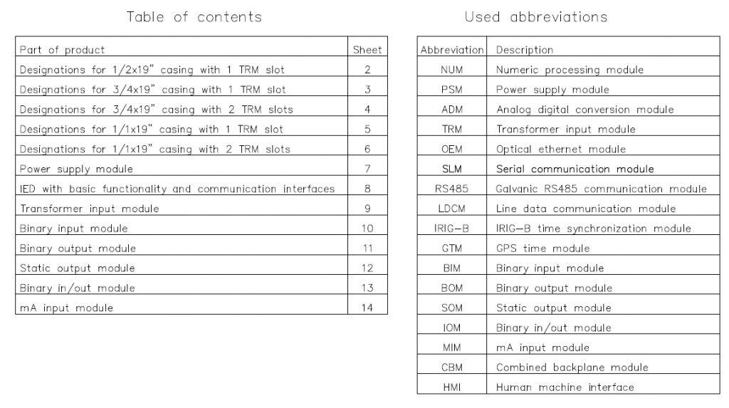
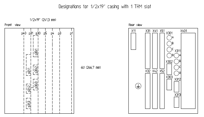
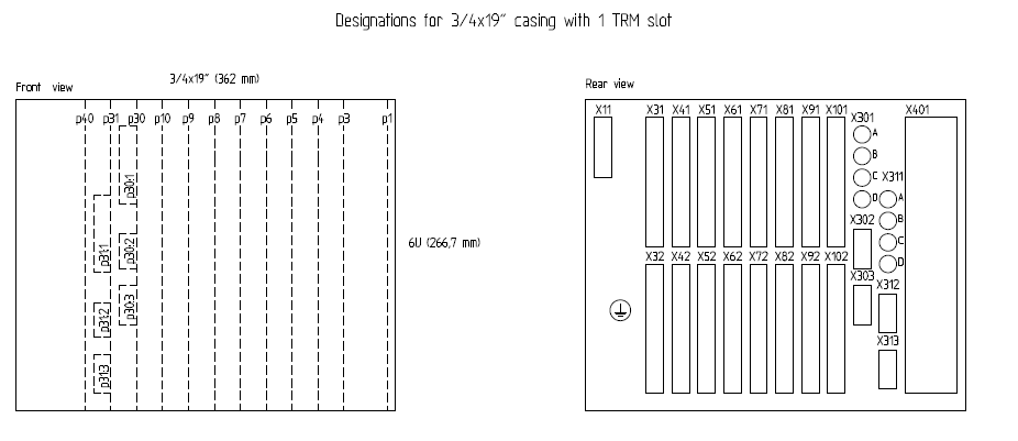
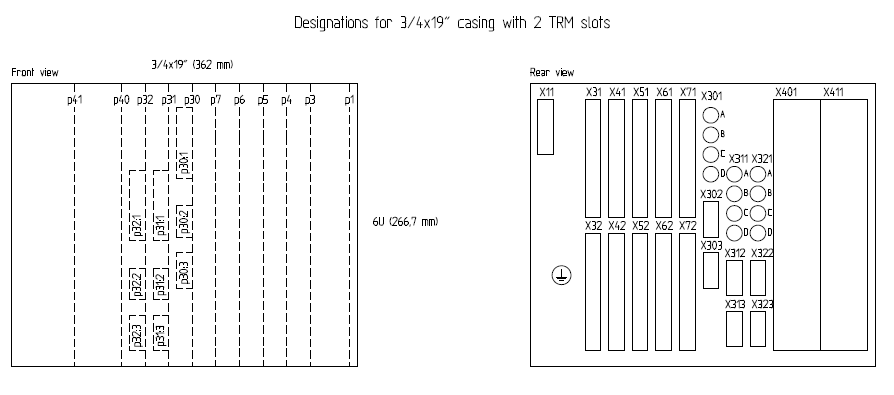
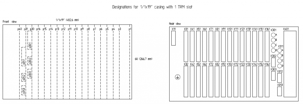
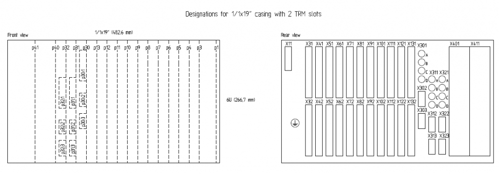
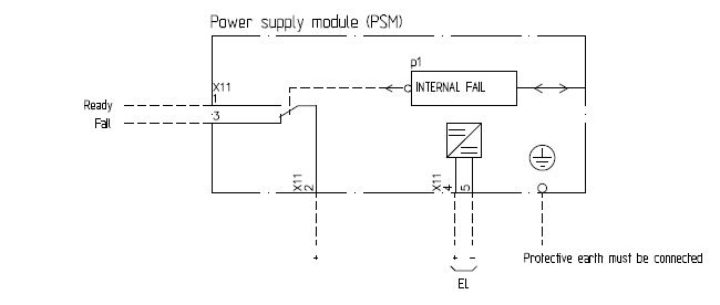
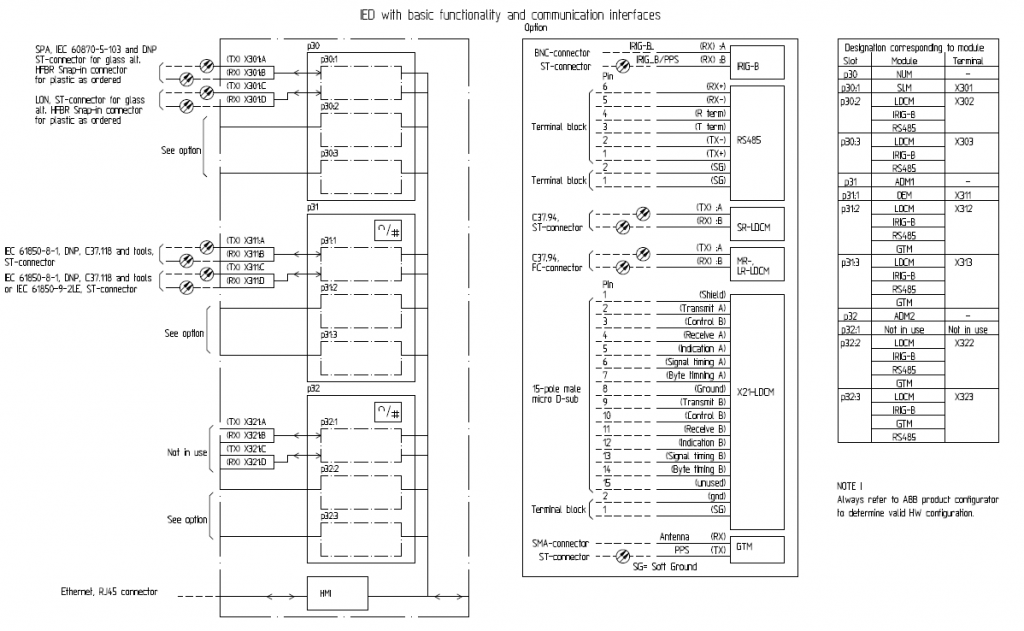
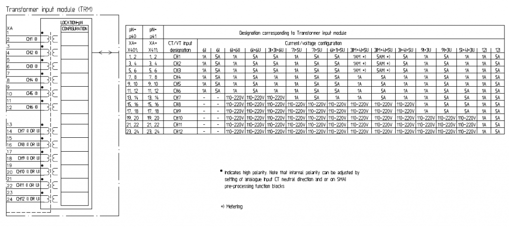
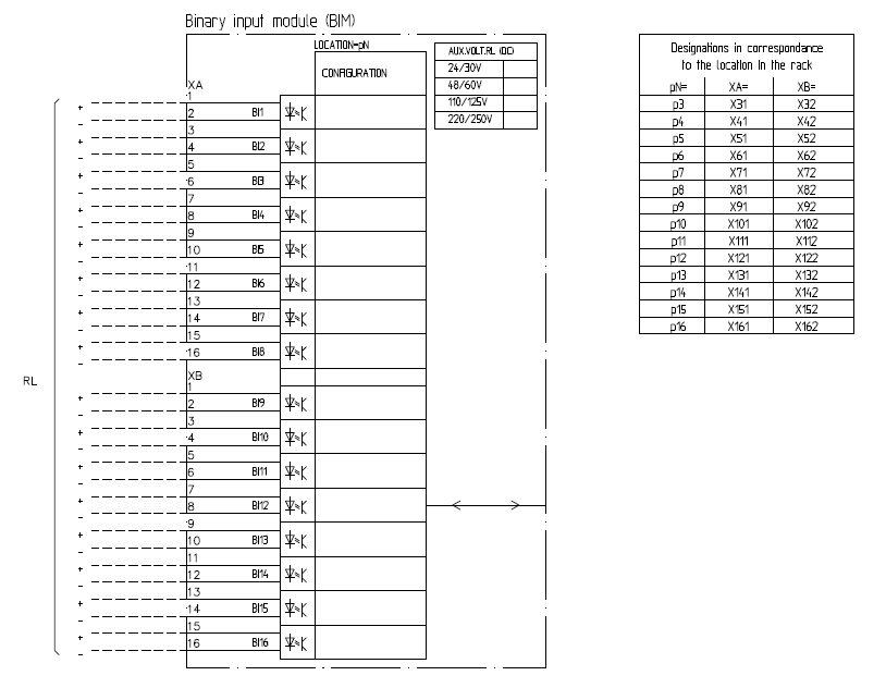
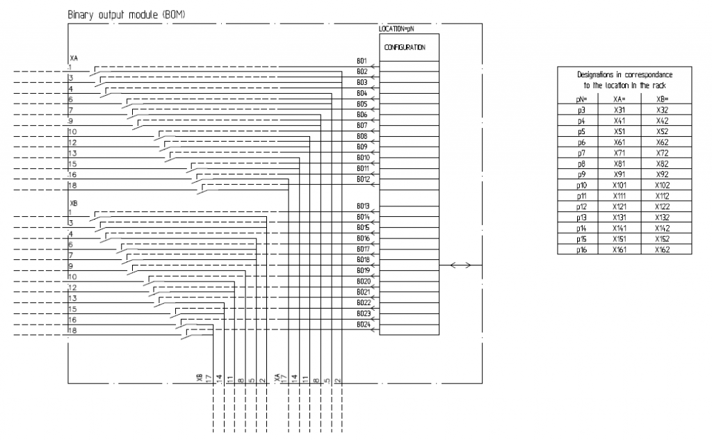
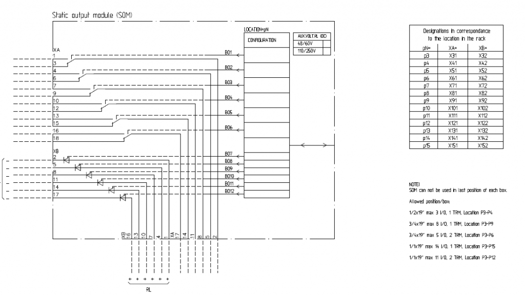
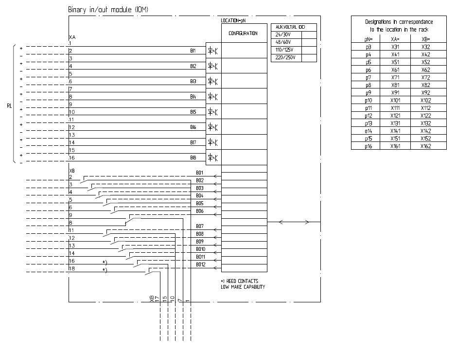
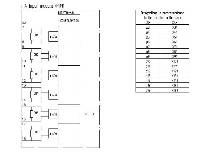
Relion 670, ABB Relion 670, ABB 670 Relay
ABB PCM 600 Video training: https://elec-engg.com/abb-pcm-600-training/

The Starter software helps you in commissioning, parameterizing, and troubleshooting the dive component where you can import all relevant data to the equipment. The software provides a graphical configuration interface for simple handling and generates the reports automatically.
This file contains the screenshot of S120 Drive full Commissioning with starter software.

Sample page of the file:
The first step is to create a new project. The DIGSI Manager has been started, a project dialog box has not yet been opened.
Click File- New of the menu bar, enter a new project name and confirm with OK.
The project dialog box is displayed.
Names and symbols of all project containers are displayed in a hierarchical tree structure. To put it less complicated, we could say that containers are displayed. This pane is called a tree view. An opened folder is the first symbol to be displayed in this pane. The opened folder is designated as project 1 and represents the top level, the project itself.
The right pane of the window shows a folder-type object. If the DIGSI 4 Remote program is installed, a phone book type object and modem type object each are displayed in addition. Otherwise, this pane of the window continues to remain empty. This page serves to display further names of symbols of objects, which are contained in one of the selected containers of the tree view. To put it less complicated, we could say that this pane shows objects. Since the right pane of the window is represented as a list, this structure is called a list view.
Up to four objects are first automatically created within a new project of the tree view.
– Project (cannot be inserted manually)
– Folder (to structure a project)
– Phone Book (station addresses for a modem connection)
– Modem (for the communication SIPROTEC between your computer and the SIPROTEC 4 device
modem connection for the storage of modem profiles).
Phone Book and modem will be created automatically if the DIGSI 4 Remote component has been loaded.
The SIPROTEC 4 device object type represents a real SIPROTEC 4 device with all its setting values and process data.
The V3/V2 device object type serves to create shortcuts linked to the V3/V2 devices within the project structure. These device data are processed with DIGSI-V3.x.
The SIPOROTEC 4 version object type is created to document different parameter settings groups of a SIPROTEC 4 device. The device address (VD number) of the corresponding versions is identical to that of the original device.

The left window pane contains the names and symbols of all project containers in a hierarchical tree structure.
The right window pane displays the objects of the selected folders. The structure is designated as a list view.
Your first step to creating a system-specific project structure is to insert folder-type blank containers in the corresponding levels.
Click a folder object to insert a subordinate folder via the menu command ® Paste. A maximum of 9 levels is the permissible hierarchy depth.
Several objects can be juxtaposed in parallel.
The names of the folders can be renamed to easily adjust to the requirements of your operation.
As a first step, you create a new project. The DIGSI 4 Manager is started, no project window is open.
The Device Catalog shows all SIPROTEC 4 devices available (installed) in the DIGSI 4 Manager.
The device catalog is an independent item. When you open the catalog, a button is created in the taskbar by Windows. The device catalog can remain open while working with the DIGSI 4 Manager to install all required SIPROTEC 4 devices.
Select a folder type object and click View ® Device Catalog to open the Device Catalog window.
The device catalog has a structure. Clicking a plus sign or double-clicking a folder icon will open the subordinate level.
For example, if you double-click 7SJ (time overcurrent protection), all installed SIPROTEC 4 devices with the device type names and the variant numbers will be displayed.
Short technical information is displayed on the lower catalog border for each device selected.
Note: Devices cannot be placed directly underneath the project folder!
The MLFB tab serves to determine the order number of the selected SIPROTEC 4 device in DIGSI 4. The order number is the code for the type and variant of the SIPROTEC 4 device. The order number is called the MLFB number.
Order number determination in DIGSI 4 affects all further parameterization options. Identical MLFB numbers are necessary for the communication between the DIGSI 4 device operation and the connected SIPROTEC 4 device. This is checked when setting up the connection.
The MLFB tab contains several drop-down list boxes. The drop-down list boxes related to the selected SIPROTEC 4 device are activated, only. These drop-down list boxes serve to select the order numbers to define the SIPROTEC 4 design and type in DIGSI 4.
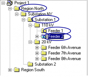
As a first step, create a new project. The DIGSI 4 Manager is started, no project window is open.
Click File ® New in the menu bar.
When creating a new project, an object of the type Hierarchical level is inserted automatically.
When creating a new project, an object of the type Hierarchical level is inserted automatically.
Properties like object name, comment, or date of creation, have been assigned to all objects (General tab).
Some properties only refer to certain objects, for ex. the MLFB number for the SIPROTEC 4 devices or the device communication settings.
The values of the majority of the properties can be changed.
Select the object and click the View ® Details menu item to display the object properties. You can also open the Object Properties dialog box via the context menu or via the menu item Edit ® Object Properties.
If the property values are grayed, they cannot be changed. Depending on the entries you made in other text boxes, such text boxes may be activated. Property values in white/empty text boxes can be edited.

Sensor technologies have made an enormous impact on modern-day industries. There are many sensors available in the market and a lot of researches is currently undergoing the development of new, smart, efficient, and high-performance sensors. In the following section, the classification of sensors is discussed.
Download IoT and smart instruments package with only 50 RS
")
DIGSI 5 is the configuration and operation tool for all SIPROTEC 5 Protection relays. with DIGSI 5, you can create system topologies, configure hardware and communication networks, set function settings, and perform many further tasks.
You perform all configuration tasks offline from your PC without the need for a SIPROTEC 5 device. You transmit all data online to the SIPROTEC 5 device later on – for example, directly through a communication network. For communication, DIGSI 5 and SIPROTEC 5 are based on current standards such as IEC 61850 and proven technologies such as Ethernet.
There are 3 different variants of DIGSI 5:
Training on DIGSI 4 and DIGSI 5 Training, contact us
Useful SIPROTEC 5 & DIGSI 5 Manuals
DIGSI 5 Software Description DIGSI 5 Software Description
SIPROTEC 5 Operation Manual SIPROTEC 5 Manual
SIPROTEC 5 Hardware Description Manual SIPROTEC 5 Hardware Description Manual
SIPROTEC 5 Engineering Guide DIGSI 5 Manual SIPROTEC 5 Engineering Guide DIGSI 5 Manual
Now DIGSI 5 V7.5 and DIGSI 5 V7.8 are also available on the SIEMENS website
DIGSI 5 Training contact us and reserve your seat.

South Australia Blackout of 28 September 2016 –was the cause due to the massive use of Renewables?
To download all of the above-mentioned topics, contact us.

Learning is a continuous process and enables us to be competitive in our field. Consistent with this belief and built on a strong experience in this field, we offer video training courses for practicing professionals in the area of Substation Automation and Protection relay. The material of each course is designed to help you to be a professional in the field.
we provide training courses at your site or online, please contact us for more information.

Power quality is simply the interaction of electrical power with electrical equipment. If electrical equipment operates correctly and reliably without being damaged or stressed, we would say that the electrical power is of good quality. On the other hand, if the electrical equipment malfunctions, is unreliable, or is damaged during normal usage, we would suspect that the power quality is poor.
As a general statement, any deviation from the normal voltage source (either DC or AC) can be classified as a power quality issue.
We can verify the power quality by installing a special type of high-speed recording test equipment to monitor the electrical power. This type of test equipment will provide information used in evaluating if the electrical power is of sufficient quality to reliably operate the equipment. The process is similar to a doctor using a heart monitor to record the electrical signals for your heart. Monitoring will provide us with valuable data, however, the data needs to be interpreted and applied to the type of equipment being powered.
To download the mentioned topics in the Power Quality package (ppt and pdf files) contact us.

Sample pages:
The system program SIGRA 4 offers support when faults occur in your network. The data recorded during fault occurrence are graphically represented and further data on the basis of the measured values are calculated in addition, like impedance or effective values, which will facilitate the evaluation of the fault record for you.
The SIGRA 4 calculations are always on the basis of primary magnitudes.
The transformer ratings are entered in the COMTRADE file of the fault record by DIGSI for evaluation by SIGRA 4.
If you want to evaluate the fault records from third-party devices recording the measured magnitudes as secondary magnitudes, you must make sure that the magnitudes will be correctly converted into primary magnitudes via the transformer ratings. The dialog box Parameterize Channels serves to carry out this parameterization. Negative ratings will cause a measured signal rotation of 180°. Thus, compatibility with the definition of the SIGRA 4 arrow metering system is ensured.
The representation and display of metered values in the secondary system is always based on the compilation ratio between the primary current or principal voltage transformer.
If metered magnitudes are created via a measuring window, this window is always left of the observation time, for ex. The cursor position. The measuring window equals the length of a period interval of the rated frequency TN, 20 ms at 50 Hz for example. The calculated magnitudes are only valid if there is no change of status displayed in the measuring window, like fault occurrence or interruption. The magnitudes calculated by SIGRA 4 are identified by an asterisk in the name.
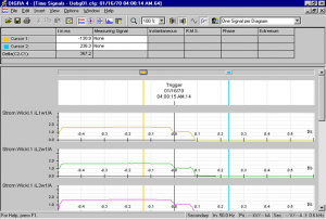
The Time Signal view serves to visualize signals as a time function.
This view serves to define any number of diagrams of the following type status diagrams:
There is the option to display the values as current or root-mean-square values.
The status diagram serves to represent the fault recording trigger time as defined status.
If user-defined status signals have been set to select individual times, these times are displayed in the status diagram with the corresponding symbol.
In addition to the graphical representation, the values of individual signals can be read at defined times from a diagram, and the current position of Cursor 1 and Cursor 2 can be read from the time axis. If a cursor is moved in a view other than that of time signals, the cursor position in the time signal view is changed, as well.
The Vector Diagram view serves to visualize measured and calculated magnitudes as complex vectors at defined times.
The diagram on the left is clearly assigned to Cursor 1 and the diagram on the right to Cursor 2.
The vector of the measured magnitudes is r.m.s. values of the harmonic component
(nominal frequency TN.). The amount and angle of the vector are determined via a full-cycle DFT (Discrete Fourier Transformation).
The measuring window is always left of the reference time (cursor position) and has the length of a time of the nominal frequency TN (for ex., 50 Hz « 20 ms).
The vector angle refers to a standard vector rotating at a nominal frequency of (fN=nominal frequency).
As a supplement to the graphical representation, you can use a diagram to read the signal values at specified times and the corresponding position of Cursor 1 and Cursor 2 on the time axis. If a cursor is moved in one view, the current vector diagram is changed, as well.

NETA Handbook Series I
NETA Handbook Series II


Download PSCAD Software
PSCAD is a simulation tool for analyzing power system transients.
PSCAD is most suitable for simulating the time domain instantaneous responses, also popularly known as electromagnetic transients of electrical systems. The PSCAD Graphical Interface greatly enhances the power and efficiency of your simulation. It allows the user to schematically construct a circuit, run a simulation, analyze the results, and manage the data in a completely integrated graphical environment.
The PSCAD/EMTDC software comes with an excellent collection of example cases, which can be used as the starting point for many of your projects. They are also used as example cases to illustrate the usage of certain complicated models, which are described best using a working example. You can also copy parts of these examples to quickly assemble your own circuits. For details on available templates see the online help system. These cases are available in your PSCAD installation directory under Examples. There is also a set of Tutorial examples in this directory.
Download Template networks in PSCAD for a transient testing package
Type: PSCAD (.pscx)
Size: 18 MB
Download PSCAD
Type: Software
Size: 93 MB
Download PSCAD Full package (Download PSCAD + Download Template networks in PSCAD for the transient testing package)

SIEMENS:
PCS 7 v9.0 + CEMAT v9.0
PCS 7 v8.2
PCS 7 v7.1 SP3
(CEMAT v7 SP1 + CEMAT v8 SP1)
TIA PORTAL v15
TIA PORTAL v14 SP1
TIA PORTAL v14
TIA PORTAL v13 SP1
➖➖
STEP 7 Professional 2017
Step 7 v5.6
Step 7 v5.5
Step 7 Pro 2010 SR4
Step 7 v5.5 SP2
Step 7 v5.5 SP4
WINCC v7.4
WINCC v7.4 SP1
WinCC Flexible 2008 SP5
WinCC Flexible 2008 SP3
WinCC Flexible 2005
➖
SIMARIS Design v9.0 SP1 + License
SIMARIS Curves v5.0 SP1
SIMARIS Project 5.1 + License
➖
STEP 7 MicroWIN V4 SP 8_9
MicriWin Smart v2.0
Drive ES Basic v5.5 SP5
Drive ES Basic v5.5 SP3
Simotion Scout V5.1, TIA
Simotion Scout v5.1, S7 5.6
Simotion Scout v4.5 Tia
Simotion Scout Standalone v4.5
Drive Monitor V5.5 SP2
SIMATIC STEP 5 Full + Crack
ITS PLS + Crack
SIMIT v9.0 SIEMENS
LOGO v8 COMFORT
LOGO v8.1 COMFORT
STARTER v4.4
STARTER v4.5 SP1
Pro Tool Pro v6 SP3
Pro Tool Pro v6 Runtime SP3
SIMATIC NET v8.2 SP1
SIMATIC NET v14 SP1
SIMATIC NET 2008 SP2
SIMATIC NET v6.2
PST v4.1 SP1
SIZER v3.15 Drive
SINET Plan v1.0 SP1
DIGSI v4.91
D7 SYS v8 _ v8.1
Desigo Insight v3.51
Pro save v9.0
WinAC RTX 2010 SP1
SICAM PAC v8.06
SiwaTool v7 Full
SIRUS STS v3
➖➖
F system v6.1
F system v6.2
S7 F Configurator
S7 Higraph v5
Safety ES v1.0 SP2
➖➖
Software EngGeo Software ESI PAM-Shock Software Abb PickMaster
Software EngiLab Beam2D Software ESI PAM-STAMP 2G Software ABB ProgramMaker
Software EngiLab Rod2D Software ESI QuikCAST Software Abb QuickTeach
Software Engine Analyzer Pro Software ESI SysWeld Software ABB RobotStudio
Software Engineered Software Flow of Fluids Premium Software ESI VA One Software ABB Robotstudio for IRC5
Software Engineered Software Pump Flo Software ESI VA-ONE Catia Importer Software ABB Shoplooreditor
Software Engineering Design with SolidWorks Software ESI Vibro-Acoustic ONE Software Abb Virtual IrC5
Software ENGINEERING DYNAMICS SACS Software ESI Visual-Environment Software ABB WebWare Client
Software Engineering Equation Solver(EES) Software ESI Welding Simulation Suite(PAM-Assembly+Weld Planner) Software ABB WebWare SDK
Software Engineering Power Tools Plus Edition Software ESOP Software ABB WebWare Server
Software ENOVIA Software ESP software Software Able Software 3D-Doctor
Software Enovia 3D Com Software ESRD StressCheck Software AbleVektor for AutoCAD
Software Enovia CA Software ESRI ArcGIS Desktop Software Absoft Fortran Pro
Software Enovia DMU Navigator Software ESRI ArcPad Software Absoft Pro Fortran
Software Enovia LCA Software ESRI CityEngine Software ABSoft Pro FortranMP7
Software Enovia Portal Software Essential Macleod Software Abvent Artlantis Studio
Software Enovia SmarTeam Software ESSS Kraken Software Abvent PhotoCAD
Software Enovia VPM Navigator Software ESSS KRAKEN Software ABViewer Enterprise
Software Ensoft Enbeamc Software Esteco modeFRONTiER Software ABZ Design Flow Solutions DesigNet
Software EnSoft Group Software Esteem Plus Software AC3D
Software Ensoft LPile Software E-studio ProHDL Software Accel-EDA
Software Ensoft Shaft Software ET GeoWizards Software AcceliCAD
Software Ensoft Stablpro Software ET SpatialTechniques Products Software Accelrys Discovery Studio
Software EnviroInsite Software ETA CAD Translator Software Accelrys DS Gene
Software Environments for Tekla Structures Software ETA Dynaform Software Accelrys Felix Desktop
Software EON CAD Software ETA Femb PC Software Accelrys Materials Studio
Software EON Carbon Scatter Multice Software ETA StrangeBrew Software Accelrys Pipeline Pilot
Software PDS 3D Software ETA VPG Software Accuform B-SIM
Software PDS IDM Software ETABS Software Accuform T-SIM
Software PDS ISOGEN Software ETANK Software ACD Systems Canvas
Software PDS SE Software ETAP Software ACD Systems Canvas with GIS
Software PDsoft 3Dpiping Software ETAP POWERSTATION Software ACE 3000 Professional
Software PeakVHDL Pro Software E-Tools E-Studio Pro Software AceCad StruCad
Software PED Professional Software ETS4 Software Acecad Strucad
Software PE-Design Software ETU Wasser Plus Software Acecoms Gear
Software PENG ENGINEERING SIMFLEX II Software EUCLID3 Software Acme CAD Converter
Software PerFect Photo Suite Software Euklid Software Acme CADSee
Software PERFORM-3D Software Euklid Software Acoustic Analyzing System
Software PERI Elpos Software Eurosoft STARK ES Software Acropora
Software PERI PeriCAD FormWork Software Eurostag Software Act3d Quest3D
Software PeriCAD Software Eware ETank Software Actel CoreConsole
Software Permedia Mpath Software E-Ware ETank2000 Software Actel Designer
Software PetraSim Software EWARM-EV Software Actel Flashpro
Software Petrel Software Excalibur Software Actel Libero IDE Platinum
Software PDMS ImPLANT-I Software EON LUMENRT Software 12D MODEL
Software PDMS ImPLANT-STL Software EON Ozone Software 2020 Kitchen
Software PDMS PML Manual Software EON Professional Software 2D Frame Analysis
Software PDMS Review Software EON Raptor Software 2D simpler
Software PDMS Suite Software EON Reality EON CAD for Deep Exploration Software 2D-Sigma
Software PDS Software EON Reality Professional Software 3Ci Geometry Works3D Features for SolidWorks
Software PDS 2D Software EON SoftWare Vue Professional Software 3D Box Maker Professional
Software PDS 2D Graphics Only Software EON Studio Software 3D Brush
Software PDS 2D PID Software EON Vue xStream for Windows and MACOSX Software 3D Shop Model design
Software Embarcadero DBArtisan Software EOS Compucon Software 3D simpler
Software Embarcadero ERStudio Software Eos Systems Photomodeler Scanner Software 3D Space TopoLT for AutoCAD
Software Embarcadero ERStudio< Software Eovia Amapi Designer Software 3D World Studio
Software Embarcadero Rapid SQL Software Eovia Amapi Pro Software 3D3S
Software Embird Software Epcon Chempro Engineering Suite Software 3Daliens Glu3D
Software Embrilliance Essentials Software EPCON Engineers Aide Toolbox Software 3DBurst for AutoCAD
Software Embrilliance Thumbnailer Software EPCON SYSTEM Process Explorer Software 3D-Coat
Software EMC Studio Software EPDRAW2000 for AutoCAD Software 43072
Software EMD WindPro Software Eplan Cabinet Software 3D-LookStailorX
Software Emeraude Software EPLAN Electric P8 Software 3DQuickForm
Software EMIT Maxwell Software EPLAN Fluid Software 3DQuickMold
Software Empirum Pro Software Eplan PPE Software 3DQuickPress for SolidWorks
Software Emrc Nisa Civil Software Eplan Pro Panel Software 3D-SHAPE 3DViewer
Software EMSight Software Eplan Pro Panel Professional Software 3D-Sigma
Software EMTPWorks Software Eplan Professional Software 3D-TOOL
Software Emu8086 Software Eplan-P8 Software 3DTools
Software Encom Compass Scout Software EPS Software 3DVIA VIRTools DEV
Software Encom Discover MapInfo Professional Bundle (includes 3D) Software EPS PanSystem Software 3DVRi
Software Encom Discover PA Software Eps Reo Software 3rd PlanIt
Software Encom Discover3D Software Eps Wellflo Software 4M FineELEC
Software Encom EMFlow Software ER Mapper Software 4M FineHVAC
Software Encom EMVision Software Erdas Software 4M FineLIFT
Software Encom Engage Software ERDAS Imagine Software 4M FineSANI
Software Encom Engage3D Software ERDAS Stereo Analyst Software 4M IDEA
Software Encom ModelVision Software ESAComp Software 533Soft Box Shot Maker
Software Encom QuickMag Software ESI ACE+ Suite Software 5D Organizer & QuickFont
Software Enercalc Software ESI CFD Advanced Software A3DStitcher
Software Energy Solutions Pipeline Studio Software ESI Foam-X Software AAS Miduss
Software Engenious Systems Inc StormShed2G Software ESI Nova Software Abacom sPlan
Software Engenius QuickPLOT Pro Software ESI PAM Stamp Software Abaqus
Software Engenius SurvOPT Software ESI PAM-CRASH 2G Software ABAQUS
Software Engenius SurvOPT Coil Software ESI PAM-DIEMAKER Software Abaqus for Catia
Software PetrisWinds Recall Software Exceed Software Actify SpinFire Pro
Software Petroleum Expert IPM Software Exceed 3D Software Active Factory
Software Petroleum Experts Software Exceed PowerSuite Software Active Map
Software Petroleum Toolbox Software Excellink for AutoCAD Software ACTRAN
Software Petroleum Toolboxes Software Excess Evolution Software ACUITIV
Software Petrolog Software Exelis (EX Ittvis) E3DE Software AcuSolve
Software Petro-Sim Software ExperionPKS Catalog Manager (Honeywell) Software Adapt ABI
Software Petrosys Software Express RIP Software Adapt Builder
Software PFC2D Software Eye4Software Coordinate Calculator Software Adapt Builder ABI
Software PFC3D Software Eye4Software GPS Mapping Software Adapt Builder EX
Software PFCAD Software Eye4Software Hydromagic Software Adapt PT
Software PGI Server Software Eyeon Fusion Software Adapt RC
Software PGI Server Complete Software Eyeon Fusion and RenderSlave Software Adasim
Software PGI Visual Fortran Software Eyeon Generation Software Adasoft Room Arranger
Software PGI Workstation Software Eyeon Generation Player Software Adem
Software PGI Workstation Complete Software EZ-FRISK Software Adina System
Software PGI Workstation Server Software EZ-Mill Turn Pro Software Adlab
Software PG-STEAMER RTP Software F A S T DBConnection Software AdLab Advanced EE Lab
Software PHA Pro Software F A S T Evolution Software AdLabPlus
Software Phase 2 Software F A S T FieldNotes Software ADLforms
Software Phast Software F A S T Fieldnotesviewer Software Adobe Acrobat
Software Phoenics Software F A S T Modbus Software Adobe Acrobat Pro CHS
Software PhotoPIA Software F A S T Piper Software Adobe After Effects Professional
Software Photoshop Fine Arts Effects Cookbook Software F A S T RTA Software Adobe AuditionAdobe GoLive
Software Photron Primatte for Fusion Software F A S T ValiData Software Adobe Creative Suite
Software PHX ModelCenter Software F A S T VirtuWell Software Adobe Creative Suite Design Standard
Software Physprops Software FAB 3000 Professional Software Adobe CS2 Bridge Services Addon
Software PiCAD Software FABmaster Gold Software Adobe FrameMaker
Software PicaSoft HandyCut Software Facegen Customizer Software Adobe Illustrator
Software PicaSoft HandyScan Software FAISYN Software Adobe InDesign
Software PicaSoft MayKa Suite Software FARO CAM2 Software Adobe Pagemaker
Software PicaSoft Stenza Software Fast Plans Software Adobe Photoshop
Software PicBasic Plus Software FAST Survey Software Adobe Photoshop Elements
Software PicBasic Pro Software Fastblank Software Adobe Premiere
Software Picbasic Pro Compiler Software Fastblank for SolidWorks Software Adobe Premiere Elements
Software Piletest PileWave Software FastCAD Software Adobe Premiere Pro
Software Pinguin Audio Meter Software FastCAM Software Adobe Version Cue
Software Pinnacle Commotion Software Fastform Advanced Software ADP
Software Pinnacle Liquid Edition Software FastFrame Software Advanced Aircraft Analysis
Software Pinnacle Studio Plus Software FB-DEEP Software Advanced PCB Design System
Software Pinnacle Studio Ultimate Software FB-Multiplier Software Advanced Road Design for AutoCAD Civil 3D
Software Pioneer Hill Software SpectraPLUS Software FB-Pier Software Advisor
Software Pipe Data Pro Software FDBES Coolpack Software AE Tools for CADVance
Software Pipe Flow Expert Software FDTD Solutions Software AEGis acslXtreme
Software Pipe Line Studio Software FEACrack Software Aegis CircuitCAM Suite
Software PipeData-Pro Software FEAP Software AFT Arrow
Software Pipedrop Software FeatureCAM Incl Solid Plugin Software AFT Chempak Viewer
Software Pipeflo Software FeatureCAM Solid Plugin Software AFT Fathom
Software PIPE-FLO Pro Software FE-Design Tosca Software AFT Impulse
Software PipeFlow 3D Software FE-Design Tosca Structure Software AFT Mercury
Software PipeFlow Advisor Software FEFLOW Software AFT Titan
Software PipeFlow Expert Software Fekete FAST CBM Software Agi32
Software PipeFlow Wizard Software Fekete FAST WellTest Software Agilent 89600 Vector Signal Analyzer
Software Pipeline Studio Software FEKO Software Agilent 89600 Vector Signal Analyzer
Software Pipeline Toolbox Software FelixCAD Software Agilent ADS
Software Pipeline Toolbox Enterprise Software FEMAP Software Agilent Advanced Design System(ADS)
Software PipelineStudio Software FEM-Design Software Agilent Antenna Modeling Design System(AMDS)
Software Pipenet Software FEMdesigner for Alibre Design Software Agilent Electromagnetic Professional(EMPro)
Software Pipenet Software FEMFAT Software Agilent EMDS
Software Pipenet Vision Software FemSIM Software Agilent GeneSpring GX
Software Pipephase Software FEMtools Software Agilent Genesys
Software Pipesim Software Fenix Software Agilent Genomic Workbench
Software PipeSUPPORT-Pro Software FEPipe Software Agilent GoldenGate
Software Piping System Fluidflow Software FE-SAFE Software Agilent Hfss
Software Piscatus 3D Software FFCAM Software Agilent IC-Cap
Software Piste Software Fides Software Agilent RF Design Environment(RFDE)
Software Pitney Bowes Encom Software Fides ARW Software Agilent Technologies SystemVue
Software PIVR Vred Software Fides Bearing Capacity Software Agilent Testexec SL
Software Pixelplan Flow Architect Studio 3D Software FIDES CantileverWall Software Agilent VEE Pro
Software Pixologic Zbrush Software Fides Drill Software AgiSoft Photoscan Pro
Software PKPM Software FIDES EarthPressure Software AI Utility for MasterCAM
Software PL7 Pro Software FIDES Flow Software AI Utility X3 For MasterCAM
Software Plane Failure Analysis Software Fides GeoPlanning Software Aicon 3D Studio
Software Planetside Software Terragen Software Fides GeoStability Software Air Humid Handling
Software PLANIT ALPHACAM Software FIDES GeoStability KEA Software Airport Facilitator
Software PLANIT EDGECAM Software Fides Ground Slab Software AIS-Sim
Software Planit S2M Software Fides KEA Software AKNM
Software PlanSwift Professional Software Fides Pilepro Software Aldec Active-HDL
Software Plant wave Software Fides PILEpro FEM Software Aldec ALINT
Software PLANT4D Software FIDES Settlement Software Aldec Riviera
Software Plantflow Software Fides Settlement2 5D Software AlgoLab Raster to Vector Conversion Toolkit
Software PlanTracer Pro Software FIDES SlipCircle Software Algor
Software Plantwave Software Fides Steel Members Software Algor Designcheck
Software PlantWAVE PDMS Software FIDES STeelCON Software Algor FEA
Software Plastics for SolidWorks Software Fides TWIST Software Algor InCAD Designer
Software Plate n sheet Software Fides WALLS Software Algor PipeCheck
Software Plate N Sheet Professional Software FIDES WALLS Dimensioning Software Algor Pipepak
Software Plaxis 2D Software FIDES WALLS FEA Software Algor Simulation Professional
Software Plaxis 3D Foundation Software Fides Walls FEM Software Alias I-Convert
Software Plaxis 3D Foundation Software FIDES WALLS Retain Software Alias I-Data Integrator
Software Plaxis 3D Tunnel Software Fides WinIGEL 3D Software Alias I-Export
Software Plaxis Software Fides WinTube Software Alias ImageStudio
Software Plaxis Professional Software FieldAlign Software Alias I-Run
Software Plaxis 3D Software Fieldgenius Software Alias I-Sketch
Software PlCAD Software FieldTemplater Software Alias I-Tools
Software Plexim Plecs Software Fieldview Software Alias I-ViewCAD
Software Plexim Plecs Standalone Software Fikus VisualCAM Software Alias Maya MasterClasses
Software Plexscap Plexearth for AutoCAD Software Filter Wiz Pro Software Alias Maya Unlimited
Software PLS CADD Software Final Cut Pro Software Alias Mental Ray
Software PLS_Cadd Software FireCAD Software Alias MotionBuilder
Software PocketStatics for Pocket PC Software FireCAD Air Heater Software Alias Piping Solutions I-Run
Software PocketStatics for Windows Mobile Software FireCAD Economiser Software Alias Piping Solutions I-View
Software Pointools Edit Pro Software FireCAD Grate Fired Boiler Software Alias Portfoliowall
Software Pointools POD Creator Software FireCAD Super Heater Software Alias SketchBook
Software Pointools View Pro Software FireCAD Water Tube Package Boiler Software Alias Spoolgen
Software Pointwise Software FirstProof Pro Software Alias StudioTools
Software Polar Instruments Software Firstvue Software Alias StudioViewer
Software Polymath Pro Software Fitness Pro Software Alias Wavefront Learning Studio Tools Level II Design Dvdrip
Software PolyWorks Software FLAC Software Alibre Design Expert
Software Portable Arguslab Software Flac2D Software Alibre Design Professiona
Software Portable ChemSketch Software Flac3D Software AlibreCAM
Software Portable GSView Software Flamingo Software AlignAndSpace
Software Portable MestReC Software Flarenet Software AlleleID
Software Portable Tinker Software Flares Software AllyCAD
Software Portable Working Model 2D Software Flaresim Software AlphaCAM
Software Poster Software Flaretot Software ALT Wellcad
Software Power Software Fledermaus Pro Software Altair HyperWorks
Software Power World Simulator Software Flexisign Pro Software Altair SimLab
Software PowerCAD Pro Software FLEXISIGN PRO Software Altera Max Plus II
Software PowerCAD SiteMaster Software Flexlm SDK Software Altera QUARTUS II
Software PowerConnect Software FlexPDE Professional 3D Software Altium Designer
Software PowerFlow for Linux Software FlexPde Professional 3D Software Altostorm Rectilinear Panorama for Adobe Photoshop
Software PowerFrame Software FlexPDE Professional 3D Software Alturion GPS European Maps
Software PowerISO Multilingual Software FlexSIM Software Amazing Designs Click N Stitch Xtra
Software PowerLog Software Flo++ Software Amazing Designs Embroidery Links
Software PowerLogic Software Floating Point Solutions Point Cloud Software Amazing Designs Fast Fills
Software PowerMill Software FloEFD Software Amazing Designs Lettering Pro
Software PowerMILL2Vericut Software FloEFD Pro Software Amazing Designs Magnificent Monograms II
Software PowerPlate Software FloEFD Pro for PTC WildFire/Creo Software Amazing Designs Size Express
Software PowerShape Software Flomerics Flo/EMC Software Amazing Designs Smart Sizer Platinum
Software PowerShape/PS-Catalogues Software Flomerics FloTherm Software AMC GPS2CAD
Software Powersim Studio Software Flomerics MicroStripes Software AMESim
Software Powersim Studio Express Software FloorPlan Software AMETANK
Software Predator VCNC Software Flow 3D Cast Advanced Software Amethys CADwizz
Software Predator Virtual CNC Software Flow Advisor Software Amethyst CADconvert
Software Pre-Design Software Flow2000 Software AMI VLAERO PLUS
Software Predict Software Flow-3D Software AMSES Frame2D
Software Prerequisites for Bentley Desktop Applications Software FLOW-3D CAST Advanced Software Amtech
Software PressCAD Pro Software Flowcalc Software Amtech ProDesign NEC
Software PRG PAULIN Software FlowCheck Software Analog Devices Visual DSP Plus Plus
Software PRG Soft (Paulin Research) Software Flowel Software Analytic Graphics STK ArcInc Basic Globe
Software Primavera Software Flowmaster Software Analytical Graphics STK Pro
Software Primavera Capital Planning and Investment Control Budgeting Software FLOWSOLV Software Analytics Platform Client
Software Primavera Contract Management Software FlowVision Software Anleggsdata Tunnplan
Software Primavera Contract Management, Business Intelligence Publisher Edition Media Pack for Microsoft Windows Software Fluent Software AnnTheGran Catalog Xpress
Software Primavera Contractor Software Fluent Airpak Software Anova Ambiente
Software Primavera Development Kit Software Fluent Fidap Software Ansoft Designer
Software Primavera Earned Value Management (32-bit) Software Fluent FloWizard Software Ansoft Designer HFSS
Software Primavera Expedition Software Fluent FlowLAB Software Ansoft Designer and Nexxim
Software Primavera Group Server Software Fluent for CATIA Software Ansoft ECAD
Software Primavera P3 Project Planner Media Pack for Microsoft Windows (32-bit) Software Fluent Gambit Software Ansoft Ensemble
Software Primavera P3e-c for Construction Software Fluent Icepak Software Ansoft Ephysics
Software Primavera P6 Software Fluent Mixsim Software Ansoft HFSS
Software Primavera P6 Enterprise Project Portfolio Management Software Fluent PakSi-E Software Ansoft Links
Software Primavera P6 Professional Project Management Software Fluent PakSi-TM Software Ansoft Maxwell
Software Primavera Portfolio Management Software Fluent Parallel Software Ansoft Maxwell 2D
Software Primavera Project Management Software Fluent Parallel Double Precision Software Ansoft Maxwell 2D 3D
Software Primavera project planner Software Fluent Parallel Single-Precision Software Ansoft Maxwell 3D
Software Primavera Risk Analysis Software Fluent PolyFlow Software Ansoft Maxwell EM Products
Software Primavera TeamPlay Client Software Fluent TGrid Software Ansoft Maxwell Rmxprt
Software PrimCAM Software Fluid Desk Coolpack Software Ansoft Optimetrics
Software Pro Engineer Software Fluid Desk Heatpack Software Ansoft PExprt
Software Pro II Software Fluid Desk Smokepack Software Ansoft Q3D
Software Pro/E Software Fluid Desk Ventpack Software Ansoft Q3D Extractor
Software Pro/E Style Software Fluid Flow3 Software Ansoft Rmxprt
Software Pro/Engineer Unigraphics, Step Software FluidDRAW Software Ansoft SCAP
Software Proach Software FluidFlow3 Software Ansoft Serenade Design Environment
Software ProArt & ProLace Software FluidSIM Software Ansoft Simplorer
Software ProCAD 2D Designer Software Fluorescence Property Utility Software Ansoft Sinewave
Software Procad 2D Designer Software Flux Software Ansoft Spice link
Software Procad 3DSmart Software Flux Got-It Software Ansoft Spiral Design Kit for Hfss
Software ProCAD 3DSMART Software FME Suite Software Ansoft TPA
Software ProCAD 3DSmart Create Software FNT3DWorks for SolidWorks Software Ansoft Turbo Package Analyzer(TPA)
Software ProCAM Software Focus Redshift Software Ansys
Software ProCAST Software FoldUP for Adobe Illustrator Software Ansys AI Environment
Software Procedural Cityengine Software FORMSYS MAXSURF Suite Software Ansys Autodyn
Software PROCEDURAL CITYENGINE PRO Software Formtec NCspeed Software ANSYS Blademodeler
Software Process IVE DIE Wizard for UG NX Software FormZ RadioZity Software ANSYS CFX Bladegen Plus
Software Process Systems Enterprise gPROMS Software Formz Renderzone Plus Software Ansys CivilFEM
Software ProcessAID Wizard for UG NX Software Forte Synthesizer Software Ansys Composite PrepPost
Software Processing Modflow Software Forward Software Ansys DesignLife
Software ProDelphi Professional Software Forward net Software ANSYS DESIGN SPACE
Software ProfiCAD Software FOXCAD Software Ansys Designspack
Software Profil Tec Software FpgaExpress Software ANSYS EKM
Software ProFILE Master 2000 CAM-DUCT Software FP-MultiPier Software Ansys Emax
Software Profili Pro Software FP-Pier Software Ansys Harvard Thermal Tas
Software Profit Software FracMan Software Ansys Harvard Thermal Taspcb
Software ProFound Effects Gak Pak Software FracproPT Software ANSYS HFSS
Software ProgeARC Software FracSIS Software ANSYS HFSS Antenna Design Kit
Software ProgeCAD Software Frame Shape Software ANSYS Icepak
Software ProgeMEC Software FrameWorks Plus Software ANSYS Maxwell 3D
Software ProgeSOFT IntelliCAD Software FrameWright Pro Software ANSYS Multiphysics
Software Progress OpenEdge Software Franson CoordTrans Software ANSYS nCode DesignLife
Software Project Engine Server And Client Enterprise Edition Software Fraunhofer SCAI MpCCI Software ANSYS ParaMesh
Software Project Messiah Studio Pro Software FRED Software ANSYS Product Intel IA32
Software Project Planner Software Fred Software ANSYS PRODUCTS
Software PROKON Software Freeship Software ANSYS Q3D Extractor
Software Prokon CalcPad Software FreeShip Software ANSYS Q3DExtractor
Software PROKON Structural Analysis and Design Software FreeWorld3D Software ANSYS Simplorer
Software Promax Software FRI Device Rating Program Software ANSYS SIwave
Software Promodel Software FRI-Database Software ANSYS SpaceClaim
Software PropertyLinks for Solidworks Software Friedrich & Lochner Statik Software ANSYS Turbo Package Analyzer (TPA)
Software ProPlan Software Friendship Framework Software ANSYS Turbogrid
Software Proplan (petroplan) Software FRI-ICES Software ANSYS WorkBench
Software ProSafe-RS Software FRI-Pack Rating Software Antenna Magus
Software ProScan Software FTI Blankworks Software AnyBody Modeling System
Software ProSimPlus Software FTI BlankWorks for SolidWorks Software AnybodyCAD for AutoCAD
Software Prosoft Flow Pro Software FTI Fastblank Software AnyCasting
Software ProSteel 3D Software FTI Fastform Advanced Software Analogic
Software Protel Software FTI FormingSuite Software Anzovin the Setup Machine
Software Protel DXP Altium Software Fuel Economy Calculator Software Apache Design Solutions RedHawk
Software Proteus Engineering FastShip Software Fugro Jason Fast Tracker Software APLUS
Software Proteus Engineering Maestro Software FullWAVE Software APM WinMachine
Software Proteus Engineering RhinoMarine Software Functor Software Apollo Photonic Solutions Suite
Software Proteus Pro Software Furret PCB Software Apollo Photonics Alds
Software Proton Development Suite Software Fxray Software Apollo Photonics Fogs BG
Software Provision Pro II Software G&P Softwares (engvert, mixprops, physprops, pipedrop, psychrocalc, stmprops) Software Apollo Photonics Foms
Software PS2000 Software GAEA Pollute Software Apple Remote Desktop
Software Psat Software GAEA Winfence Software Applied Flow Technology Arrow
Software PSC Design Kit Software GAEA Winlog Software Applied Flow Technology ChemPak
Software PSCAD Software GAEA WINLOG Software Applied Flow Technology ChemPak Viewer
Software PSCAD pro Software GAEA Winsieve Software Applied Flow Technology Engineering Utility Suite
Software PSE gPROMS Software GAGEtrak Software Applied Flow Technology Fathom
Software PSIM Plus Software Gaia Software Applied Flow Technology Impulse
Software PSIM Professional Software GaLa Reinforcement Software Applied Flow Technology Mercury
Software PSoC Designer Incl C Compiler Software Galaad Software Applied Flow Technology SteamCalc
Software Pspice Software Gambit MIMIC Simulator Suite Software Applied Flow Technology Titan
Software PSS Viper Software Gambit MIMIC Virtual Lab CCNA Software Approach
Software PSS/E Software GAMMA TECHNOLOGIES Software Aps-Ethos
Software PTC 3DPaint Software Garden Organizer Deluxe Software Apsim
Software PTC 3DPAINT Software GardenGraphics DynaSCAPE Professional Software Aquaveo GMS
Software PTC Arbortext Software Garmin MapSource Atlantic Software Aquaveo SMS
Software PTC Arbortext IsoDraw Software Gastroplus Software Aquaveo WMS
Software PTC Cadds Software Gasvent Software ArcGIS
Software PTC CDRS Software Gatech GT Strudl Software ArcGIS ArcSDE
Software PTC Cocreate Software Gatecycle Software ArcGIS DeskTop
Software PTC Cre Expert Moldbase Extension (EMX) Software Gaussian Software ArcGIS Server
Software PTC Creo Software GaussView Software ArcGis Workstation
Software PTC Creo Elements View Software Gcap Software Arch
Software PTC Creo Elements/Pro Software Gcode2000 Software Archicad
Software PTC Creo Parametric PDX Software GC-PowerStation Software Archon Engineering Mechanical Toolbox
Software PTC Creo Schematics Software GE Gatecycle Software Archon Engineering Psychrometric Chart
Software PTC Creo Schematics Software Gearbox Software Archon Engineering Steam Tables
Software PTC Creo View Software GearTeq Software ArcIMS
Software PTC Creo/Illustrate Software GearTeq for Autodesk Inventor Software ArcInfo WorkStation
Software PTC Division MockUp Software GearTeq for SolidWorks Software ArcPad
Software PTC Division Visual Collaboration Services Software GearTeqSE Software ArcReader
Software PTC EMX Software GearTrax Software ArcSDE
Software PTC Expert Framework Extension Software GearTrax AI for Inventor Software Arcv2CAD
Software PTC ICEM DDN Software GearWizard Software ArcView
Software PTC ICEM Surf Software Gearwizard for UG NX Software ArcView 3D Analyst
Software PTC ICEM Surf training Software Gehry Technologies Digital Project Software ArcView GIS
Software PTC InterComm EDAconduit Software Gemalto Developer Suite Software ArcView Image Analyst
Software PTC InterComm Expert Software Gemcom GEMS Software ArcView Internet Map Server
Software PTC Mathcad Software Gemcom MineSched Software ArcView Network Analyst
Software PTC Mathcad Prime Software Gemcom Minex Software Arden Software Impact
Software PTC Pro Cabling Software Gemcom Surpac Software Ardence RTX SDK
Software PTC PRO ENGINEER WILDFIRE Software Gemcom Whittle Software Ariel Performance Analysis System
Software PTC Pro ToolMaker Software Gemini CAD Systems Software Arm & Mips
Software PTC Pro/Concept Software Gemini Cut Plan Software ARMD
Software PTC Pro/E Manikin Population Data Software Gemini Nest Expert Software ARM Developer Suite
Software PTC Pro/E RSD Software Gemini Pattern Editor Software ARM DS5 with RVCT
Software PTC Pro/E SuperTools Software Gemini Photo Digitizer Software ARM Firmware Suite
Software PTC Pro/E WildFire Graphics Library Software Gemvision Matrix Software ARM RealView Developer Suite?RVDS)
Software PTC Pro/E WildFire+Pro/Mechanica Software Geneious Pro Software ARM SOC Designer
Software PTC Pro/Intralink Software Genemation GenCrowd 3D Software ARM Software Development Toolkit
Software PTC Pro/Intralink Oracle Software Genesis Software ArmaCAD
Software PTC Progressive Die Software Genesis Frontline Software Array Designer
Software PTC Progressive Die eXtension Software GENESIS32 Software ARRIS
Software PTC Routed Systems Designer Software GeniUS for AutoCAD Software ARTAS SAM
Software PTC Windchill Software Geo5 Software ArtCAM
Software PTC Windchill+Pro Intralink Software Geoandsoft Cecap 32 Software ArtCAM Advantage
Software PTGui Software Geoandsoft Clasrock 32 Software ArtCAM Insignia
Software PTV VISSIM Software Geoandsoft Clu_star 32 Software ArtCAM Jewelsmith
Software Pulse Tajima DG ML Software Geoandsoft Eletom 32 Software ArtCAM Pro
Software Pulsonix Software Geoandsoft Happie 32 Software ArtCut
Software Pulsonix Advanced Electronics Design System Software Geoandsoft Ila32 Software ARTeMIS Extractor
Software PumpBase Software Geoandsoft Isomap 32 Software ARTeMIS Testor
Software Pumpcalc Software Geoandsoft Rock3D32 Software ArtiCAD Pro
Software PureBasic Software Geoandsoft Rotomap 32 Software ArtiosCAD
Software PV Fabricator Software GeoandSoft SID32 Software ArtsAcoustic Reverb
Software PVCAD Software Geoandsoft Vercam32 Software ArtSoft Mach3
Software PVElite Software Geoandsoft Well32 Software ArtWork Conversion
Software Pvfabricator Software GeoCad Software ASAP Pro
Software Pvsol Software GeoCAP Software ASDE for AutoCAD
Software PVS-Studio Software Geocap Software ASDIP Concrete
Software PVsyst Software GEOCatalog Software ASDIP Foundation
Software PVTflex Software Geocentrix ReActiv Professional Software ASDIP Retain
Software PVTsim Software Geocentrix Repute Software Asdip Steel
Software Pyrosim Software Geocentrix ReWaRD Professional Software Asgvis Vray for Rhino
Software Pythagoras CAD GIS Software GeoControl Software Ashampoo 3D CAD Architecture
Software Pythagoras Software GeoDelft MFoundation Software Ashlar Cobalt
Software QCAD Software Geodelft Mpile Software Ashlar-Vellum Graphite
Software QCad Software GeoDelft MSeep Software Ashrae Handbook
Software Q form Software GeoDelft MSettle Software ASM Material Handbooks
Software Qmsys Tolerances And Fits Software GeoDelft MStab Software Aspen B-JAC
Software QNX Momentics Development Suite Professional Edition Software GeoDelft MWatex Software Aspen Exchanger Design and Rating (EDR)
Software QNX Momentics Professional Software GeoDLL Software Aspen Flare System Analyzer
Software QNX Neutrino8 Software GeoFEA Software Aspen Flarenet
Software QNX Realtime Platform Software GeoFrameworks GIS NET for All Platforms Software Aspen Hysys
Software QuadriSpace Document3DSuite Professional Software Geographix Discovery Software Aspen Icarus
Software Quadstone Paramics Software GeoGraphix DSS Software Aspen MUSE
Software Quark XPress Passport for MAC OSX Software GeoLogger Software Aspen ONE Suite
Software QuarkXPress Portable Software Geologynet FieldT Software Aspen Operations Support
Software Quarry Software Geomagic Cadmus Fashion Software Aspen Orion
Software Quest Central For Databases Software GeoMagic eShell Software Aspen Petroleum Supply Chain
Software Quest3D VR Edition Software GeoMagic Foundation Software Aspen PIMS
Software Quickie CAD Symbols Designcad Software Geomagic Qualify Software Aspen Plus
Software Quickie CAD Symbols DFX Software GeoMagic Spark Software Aspen Process Development
Software QuikLogic QuickWorks Software Geomagic Studio Software Aspen Refsys
Software Quint Optishape-TS Software GeoMap Software Aspen Suite
Software R2V Software Geomatic Studio Software ASPEN ONE
Software RAD Studio Delphi Software Geomedia Covadis Software ASPEN ONE PLUS
Software Radiant ProMetric Software Geomesh Software AspenTech AspenONE Engineering Siute
Software Radimpex ArmCAD Software Geometric DFMPro for SolidWorks Software AspenTech AspenONE HYSYS
Software Radimpex Tower Software Geometric GeomCaliper for Catia Software Asphalt Pavement Thickness Design Software
Software Radish Works Cosmos Creator Software Geometric GeomCaliper for ProE Software Asphalt Test Report System
Software Radtherm Software Geometry Expressions Software Asset Management for CADVance
Software RainCAD for AutoCAD Software GeometryWorks Software Assimilate Scratch
Software RAM Concept Software GeometryWorks3D Features Software Asvic Software Mech-Q
Software RAM Connection Software GeoniCS Civil Software Atd Edit
Software RAM Elements Software GEO-office Software Atena
Software RAM Structural System Software Geopainting GPSMapEdit Software Atir Strap
Software RamSeries Professional Software Geophysical Software Solutions(GSS) Potent Software AtLast SketchUp
Software Rand 3D Caliper for Pro E Wildfire Software GEO-Slope Geostudio Software Atmel Studio
Software Rand Automation Gateway For Pro/E Wildfire Software GEO-Slope Office Software Atoll
Software Rand TailorMade Configurator Software GEO-Slope Vadose Software Atomistix ToolKit
Software Rapidform Software GEOSOFT CoStat Software Atomistix Virtual NanoLab
Software Rasterex RxView & RxHighlight Software Geosoft Eletom Software ATP EMTP
Software Rasterstitch Panorama Software Geosoft Insitu Software ATPDRAW
Software Rastervect Software Geosoft Liquiter Software Atrenta SpyGlass
Software Rational Acoustics Smaart Software Geosoft Oasis Montaj Software AUDACES
Software RCM ACI-Builder (Design of Reinforced Concrete Members according to ACI318-05) Software Geosoft Target Software AutoCAD
Software RCP Developer Software Geosoft Target for ArcGIS Software Autocad Inventor Professional
Software Reaction Design Chemkin Software GeoSolve Slope Software AutoCAD LT
Software Reaction Design Chemkin Pro Software GeoSolve Wallap Software AutoCAD Mechanical
Software Readiris Pro Software GeoStru Geotecnica Software AutoCAD Mep
Software Real Steel for AutoCAD Software Geostru Hydrologic Risk Software AutoCAD P&ID
Software Real-Time Rendering Software Geostru MDC Software AutoData
Software Reallusion Iclone Studio Software GeoStru Slope Software AUTODATA
Software RealPic Simulator Software GeoStru SPW Software AutoDeblur and AutoVisualize Gold
Software Realviz ImageModeler Software GeoSystem Delta Software AUTODECK CAMDUCT
Software Realviz Movimento Software GeoTools Software AUTODESK 3DSMAX DESIGN
Software Realviz Stitcher Software GeoTools Software Autodesk Algor Simulation Pro
Software RealVIZ Stitcher Unlimited Software Geoway Software Autodesk Algor Simulation Professional
Software RecurDyn Software GeowayDRG Software Autodesk ALIAS
Software Red Giant Composite Wizard for After Effects Software Geoweb 3D Software Autodesk Alias Automotive
Software Red Giant iMage Lounge for After Effects Working Software Gerber 3D V-Stitcher Software AUTODESK ALIAS AUTOMOTIVE
Software Red Giant Magic Bullet Editors for Premiere Pro Software Gerber AccuMark Software AUTODESK ALIAS DESIGN
Software Red Giant Magic Bullet Suite Software Gerber OMEGA Software AUTODESK ALIAS SURFACE
Software ReflectorCAD Software GerbTool Software Autodesk Architectural Desktop
Software Reflex 2D Quick Software GetSolar Professional Software Autodesk Autocad
Software Reflex 3D Scan Software GGU Axpile Software AUTODESK AUTOCAD ARCHITECTURE
Software Reflexw Software GGU Borelog Software Autodesk AutoCAD Civil 3D
Software ReiWorld Staad Beam Software GGU CAD Software Autodesk AutoCAD Civil3D Land Desktop Companion
Software Reiworld Staad Beam Software GGU Consolidate Software AUTODESK AUTOCAD DESIGN SUITE ULTIMATE
Software Relex Software GGU Directshear Software Autodesk AutoCAD ECSCAD
Software RenderMan Software GGU Drawdown Software Autodesk AUTOCAD ELECTRICAL
Software Renesas CC32R Software GGU Footing Software Autodesk Autocad Inventor Professional
Software Renesas High-Performance Embedded WorkShop Software GGU Gabion Software AUTODESK AUTOCAD LAND DESKTOP
Software Renesas NC308WA Software GGU GGUCad Software AUTODESK AUTOCAD MAP 3D
Software Renesas NC30WA Software GGU Labperm Software Autodesk AutoCAD Map3D
Software Res2Dinv Software GGU Latpile Software Autodesk AutoCAD Mechanical
Software Res3Dinv Software GGU Plateload Software Autodesk Autocad Mechanical Desktop
Software Research Mathematica Software GGU Pumptest Software Autodesk AutoCAD MEP
Software Research Systems Envi Software GGU Retain Software AUTODESK AUTOCAD MEP
Software Research Systems IDL Software GGU Seep Software Autodesk AutoCAD P&ID
Software Reservoir Evaluation Programme(REP) Software GGU Settle Software AUTODESK AUTOCAD PID & ID
Software ReSpectrum Software GGU SS Flow 2D Software Autodesk AutoCAD Plant 3D
Software Retail ICE Software GGU SS Flow 3D Software AUTODESK AUTOCAD PLANT3D
Software Retain Pro Software GGU Time Graph Software Autodesk AUTOCAD RASTER DESIGN
Software RetainWall Software GGU Transient Software Autodesk AutoCAD Raster Design
Software Review Software GGU Trench Software AUTODESK AUTOCAD RASTER DESIGN
Software Revisionfx Reelsmart Motion Blur Pro for DF4 Fusion Software GGU Triaxial Software Autodesk AutoCAD Revit Series
Software Revisionfx Reflex for Fusion Software GGU Underpin Software Autodesk AutoCAD Revit Structure Suite
Software Revisionfx Twixtor Pro Software GGU-Slab Software Autodesk AutoCAD Structural Detailing
Software Revit extensions for Robot Software GGU-Stability Software AUTODESK AUTOCAD STRUCTURAL DETAILING
Software Revit Project Browser-Software GGU-Time set Software AUTODESK AUTOCAD UTILITY DESIGN
Software Revworks for Solidworks Software GH-Bladed Software Autodesk Autosketch
Software Rhino 3D Software Gibbs Software AUTODESK BUILDING DESIGN SUITE ULTIMATE
Software Rhinoceros Software GibbsCAM Software Autodesk Building Systems
Software Rhinoceros Corporate Edition Software GiD Professional Software Autodesk CAD Overlay
Software Rhinoceros Final Software G-Info for AutoCAD Software Autodesk CadBlocks
Software Rib Construction Suite Software Gis BasePac Software Autodesk Camnetics CamTrax
Software RIBASIM Software GIS Feature Collection Module for Boeing SoftPlotter Software Autodesk CamTrax
Software Ricardo Mechanical Suite Software Global Energy Mapper Software Autodesk Civil Design
Software Ricardo Wave Software Global Mapper Software Autodesk Cleaner XL
Software Richpeace Garment CAD Software Global Tracks 2003 Software Autodesk Combustion
Software Right Hemisphere Deep Exploration CAD Edition Software GlobalCAD ADT Schedule Software Autodesk Composer
Software Right Hemisphere Deep Exploration JT PMI Module Software GlobalCAD Architecture Software Autodesk Data Management Server
Software Right Hemisphere Deep Paint 3D Software GlobalCAD Exchange Software Autodesk Design Review
Software Right Hemisphere Deep UV Software GlobalCAD Hatch Manager Software Autodesk DirectConnect
Software Right Hemisphere SAP Visual Enterprise Author Software GlobalCAD LandARCH Software Autodesk DirectConnect For UG NX
Software Rimu PCB Software GlobalCAD Organizer Software Autodesk DWF Composer
Software RISA 2D Software GlobalCAD Schedule Software Autodesk DWF Writer
Software RISA Connection Software GlobalCAD Symbols Pack Software Autodesk DWG Viewer
Software RISA FLOOR Software GlobalCAD Terrain Software Autodesk Ecotect Analysis
Software RISA Foot Software GlobalCAD Toolbox Software AUTODESK ENTERTAINMENT CREATION SUITE ULTIMATE
Software RISA Foundation Software GLOBE Claritas Software Autodesk Fabrication CADmep
Software RISA Masonry Software GL-Studio Software Autodesk Fabrication CAMduc
Software RISA Tower Software GMI Caliper Software Autodesk Fabrication ESTmep
Software Risa Tower Software GMI Imager Software Autodesk Fabrication FABme
Software RISA-3D Software GMI ModelBuilder Software AUTODESK FACTORY DESIGN SUITE
Software RISASection Software GMI Mohrfracs Software Autodesk Factory Design Suite Ultimate
Software Riskplot Graphic Software GMI PressCheck Software Autodesk FDSU
Software Rittal RiCAD 3D Software GMI SFIB Software Autodesk IFFFS
Software Riverware Software Gmi Stilista Software Autodesk Image Modeler
Software RO Software Perfect Software GMI WellCheck Software Autodesk ImageStudio
Software RoboGUIDE Software GoCAD Software Autodesk Impression
Software Robot Millennium Office Software Gocad Software Autodesk Infrastructure Modeler
Software Robot Robin Software Golden Software Didger Software AUTODESK INFRASTRUCTURE MODELER
Software RobotC for Arduino Software Golden Software Grapher Software Autodesk Inventor LT
Software RobotC for Mindstorms Software Golden Software MapViewer Software Autodesk Inventor Pro
Software Rockware AqQA Software Golden Software Strater Software AUTODESK INVENTOR PRO
Software Rockware Aqqa Software Golden Software Voxler Software Autodesk Inventor Professiona
Software Rockware Downhole Explorer Software Golder Associates GasSim Software AUTODESK INVENTOR PUBLISHER
Software RockWare GIS Link for ArcGIS Software GoldSim Software Autodesk Inventor Suite Pro
Software Rockware LogPlot Software GoldSize Software Autodesk Inventor Tooling
Software RockWare QuickSurf Software GoldTools for MapInfo Software AutoDesk Land Desktop
Software RockWare QuickSurf for Autodesk AutoCAD Software GPMAW Software Autodesk Landxplorer Studio Pro
Software RockWare RockPack III Software gPROMS ModelBuilder Software AutoDesk Lustre
Software Rockware Rockworks Software GPS CAD Transfer Software Autodesk MapGuide
Software Rockwell Automatio Drive Executive Software GPS Lab Professional Software Autodesk MapGuide Author
Software Rockwell Automation ARENA Software GPS NET Visualization Tools Software Autodesk MapGuide Documentation
Software Rocscience Dips Software GPS Tools SDK Software Autodesk MapGuide Dynamic Authoring Toolkit
Software Rocscience Examine2D Software GPS Trackmaker Software Autodesk MapGuide Enterprise
Software Rocscience Examine3D Software Grafis Software Autodesk MapGuide LiveView
Software Rocscience ExamineTab Software Graitec Advance Software Autodesk MapGuide SDF Component Toolkit
Software Rocscience Phase2 Software Graitec Advance Concrete Software Autodesk MapGuide SDF Loader
Software Rocscience RocData Software Graitec Advance Steel Software Autodesk MapGuide Server
Software Rocscience RocFall Software Graitec Advance Suite Software Autodesk Mapguide Studio
Software Rocscience RocLab Software Graitec OMD Software Autodesk Maya
Software Rocscience RocPlane Software GraphingCalc Software Autodesk Modbox Pro
Software Rocscience RocSupport Software Graphisoft ArchiCAD Software Autodesk Mold Flow
Software Rocscience Settle 3D Software Graphisoft Archicad Software AUTODESK MotionBuilder
Software Rocscience Slide Software Graphisoft ArchiCAD Software Autodesk Mudbox
Software Rocscience Swedge Software GraphiSoft ArchiGlazing Software Autodesk NavisWorks Manage
Software Rocscience Unwedge Software Graphisoft Archiglazing Software Autodesk NavisWorks Review
Software RokDoc Software GraphiSoft ArchiGlazing for ArchiCAD Software Autodesk Navisworks Simulate
Software RomansCAD Software GraphiSoft CYMAP CADLink Software Autodesk Navisworks Suite
Software Romax Software Suite Software GraphiSoft DuctWork Software AutoDesk Onsite EnterPrise
Software Rope Editor Plus for LightWave Software GraphiSoft DuctWork for ArchiCAD Software AUTODESK PLANT DESIGN SUITE ULTIMATE
Software Rotating Inertia Calculator Software Graphisoft EcoDesigner Software AutoDesk PRE-Plan
Software RotorInsa Software Graphisoft MEP Modeler Software AUTODESK PRODUCT DESIGN SUITE ULTIMATE
Software Routable cGPSmapper Software Graphite Software Autodesk Productstream Explorer
Software Rowley Associates CrossWorks for ARM Software Graphitech CimaGrafi Engravingfonts Software Autodesk Productstream Professional
Software Rowley Associates CrossWorks for AVR Software Graphitech Cimagraphi Software Autodesk Productstream Replicator
Software Rowley Associates CrossWorks for MAXQ Software Graphitech CopyMate II Software Autodesk Project Vasari Technology Preview
Software Rowley Associates CrossWorks for MSP Software Graphitech Rams Gold Software Autodesk Quantity Takeoff
Software Roxar EnABLE Software GraphPad InStat Software AUTODESK QUANTITY TAKEOFF
Software Roxar IRAP RMS Software GraphPad Prism Software Autodesk Raster Design
Software RScript Software GratingMOD Software Autodesk Revit
Software RSI BOM Explorer Software Green Hills SoftWare Multi For Arm Software AUTODESK REVIT
Software RSI CAMCAD Pro Software Green Hills Software MULTI for MIPS Software Autodesk REVIT AMS
Software RSLogix 5000 Software Greenworks XFrog Software Autodesk Revit Architecture
Software RSoft DataBROWER Software Greenworks Xfrog for C4D Software Autodesk Revit Building
Software RSoft LinkSIM Software GreenWorks XFrog for Cinema4D Software Autodesk Revit Extensions
Software RSoft MOST Software GreenWorks Xfrog for Maya Software Autodesk Revit MEP
Software RSoft Photonics CAD Suite Software Greenworks XFrog Tune Software Autodesk Revit Mep Suite
Software RunGE Talpac Software Grenander Software Workshop LoudSpeaker Lab Software Autodesk Revit Structure
Software RunGE XPAC Software GridPro Software Autodesk Robot Structural Analysis Pro
Software Rx AutoImage Pro Software Griffo Brothers Camlink Software Autodesk Robot Structural Analysis Professional
Software Rx Spotlight Pro Software GroundMap Software Autodesk Showcase
Software SACS Software GS AFES Software Autodesk Simulation CFD
Software SadloCAD Software GSE System Sim Suite Pro Software Autodesk Simulation DFM
Software Safe Software FME Software GStarCAD Pro Software Autodesk Simulation Mechanical
Software Safe Software FME Desktop Software GSTool Software Autodesk Simulation MoldFlow Adviser Ultimate
Software SAFE TECHNOLOGY FE-SAFE Software GT Works/GT Designer Software Autodesk Simulation Moldflow CAD Doctor
Software Safer Systems Trace Software GTSoft Span Beam Analysis Software Autodesk Simulation Moldflow Design Link
Software Sage Profile Software GTSoft SupportIT Excavation Support Software Autodesk Simulation Moldflow Insight Ultimate Server
Software Sage-Crisp Software GT-Suite Software Autodesk Simulation MoldFlow Synergy
Software Samcef For Wind Turbines Software GTXRaster CAD Plus for AutoCAD Software Autodesk Simulation Multiphysics
Software Samcef Student Software Gulf Publishing Company Est$Pro Software Autodesk Sketchbook Designer
Software SAM-LEAP Software Guthrie Arcv2CAD Software Autodesk Sketchbook Pro
Software Sandia Software Cadrail Software Guthrie CAD Viewer Software Autodesk Sketchbook Pro For Enterprise
Software Sante DICOM Editor Software Guthrie CAD2Shape Software Autodesk Smoke
Software Sante DICOM Viewer Pro Software Guthrie QA CAD Software Autodesk Softimage
Software SAP 2000 Software Guthrie QACAD Software Autodesk SoftImage Face Robot
Software SAP Business Objects Enterprise XI Software Gutrhie CAD GIS collection Software Autodesk Spreadsheet Calculator for Autodesk Robot Structural Analysis Pro
Software SAP Module Software GW3Dfeatures For SolidWorks Software Autodesk Stitcher UnLimited
Software SAP Visual Enterprise Author Software GXII Software Autodesk StudioViewer
Software Saphir Software G-Zero Lathe Software Autodesk Survey
Software Sapphire FOR AE OSX Software G-Zero Mill Software AutoDesk Survey
Software SAS JMP Statistical Discovery Software H&R Resources Centrix Software Autodesk Toxik
Software SASCAD Software Haliburton Decision Space(DSS) Software Autodesk Vault
Software Satmaster Pro MK Software Haliburton Drill works predict Software Autodesk Volo View
Software SatPC32 Software Halliburton Engineer’s Data Model Software Autodesk Vred Presenter
Software SB200 StackUp Builder Software Hamic Software AutodeskPortfoliowall
Software SB200 StackUp Viewer Software Hampson Russell CE Software Autodsys AcceliCAD2CAM
Software SC/Tetra Software Hans Gerd Duenck Kerst AllTrans Software Autodsys ArchT
Software SCAD Office Software Harlequin Ecrm RIP Software Autodsys IntelliCAD
Software Scandpower Petroleum Technology Group Drill Bench & Ubit Software Hash Animation Master Software AutoFab
Software Scandpower Petroleum Technology Group IPOS Software HazardReview Leader Software AutoForm Plus
Software Scandpower Petroleum Technology Group Mepo Software HBM nCode Software AutoHook for AutoCAD
Software Scandpower Petroleum Technology Group OLGA Software HDL Companion Software AutoManager WorkFlow
Software Scandpower Petroleum Technology GROUP DrillBench Software HDL Design Entry EASE Software Automation Studio
Software Scandpower Petroleum Technology Olga Software HDL Turbo Writer Software AutoMation Studio Pro
Software Scanpower Mepo Software HDL Works IO Checker Software AutoMationworx Software Suite
Software ScanSoft OmniPage Software Heidelberg Prinect MetaDimension Software Automod
Software Scanvec Amiable Enroute Software Hexagon Software AutoNest for AutoCAD
Software Schlumberger Aquachem Software Hex-Rays IDA Professional Software AutoPIPE
Software Schlumberger AquiferTest Software Hgen 2006 for AutoCAD Software Autoplant
Software Schlumberger CemCade Software HGTV Home and Landscape Platinum Suite Software AutoPlant 3D
Software Schlumberger Cougar Software HHK GEOgraf Software Autopol
Software Schlumberger Drilling Office Software HHK GEOgraf CAD Software AutoPOL
Software />Schlumberger Eclipse Software HHK GEOgraf ViewerPRO Software AutoSEA2
Software Schlumberger FracCADE Software Highway Capacity Software – HCS 2000 Software AutoShip
Software Schlumberger FracCade Software HIS Petra Software AutoTrack
Software Schlumberger GeoFrame Software HI-TECH ADP Software AutoTRAX EDA
Software Schlumberger Geoframe For Linux Software Hi-Tech dsPicc Software AutoTurn
Software Schlumberger GeoQuest Eclipse Software Hi-Tech Picc Software Autovue
Software Schlumberger Hydro GeoAnalyst Software HI-TIDE Software AutoVue Electro-Mechanical Pro
Software Schlumberger Hydro GeoBuilder Software Holophase CirCAD Software AutoVue SolidModel Pro
Software Schlumberger INTERACTIVE PETROPHYSICS Software Home Plan Pro Software Autovue SolidModel Professional
Software Schlumberger Interactive petrophysics Software Honeywell PredictPipe Software AutoXlsTable for AutoCAD
Software Schlumberger Merak Peep Software Honeywell RiskIT Software Auyodesk InfraWorks
Software Schlumberger modflow Software Honeywell Socrates Software Avenza Geographic Imager
Software Schlumberger MODFLOW Flex Software Honeywell Strategy-A Software Avenza Geographic Imager for Photoshop
Software Schlumberger OFM Software Honeywell Strategy-B Software Avenza MAPublisher
Software Schlumberger Oil Field Manager(OFM) Software Honeywell Unisim Design Software Avenza Mapublisher for Photoshop
Software Schlumberger Omega Software Honeywell UniSim Flare Software AVEVA E3D
Software Schlumberger Osprey Operations Manager Software Horizontal Drilling Software AVEVA Everything 3D
Software Schlumberger Osprey Reports Software Hotdoor CADtools for Adobe Illustrator Software AVEVA Explant
Software Schlumberger Osprey Tubular Designer Software Hourly Analysis Program Software AVEVA Implant
Software Schlumberger Perforating Analysis (SPAN) Software HSC Chemistry Software AVEVA ImPLANT-STL
Software Schlumberger Petrel Software HSM for Mastercam Software AVEVA Instrumentation
Software Schlumberger PetroMod Software HSM Performance Pack Software AVEVA MARINE
Software Schlumberger Pipesim Software HSMWorks Software AVEVA Open steel
Software Schlumberger ProSource Software Hspice Software AVEVA P&ID Integrator
Software Schlumberger ProSource Seismic Manager Software HTFS Software AVEVA P&ID Manager
Software Schlumberger Span Software HTFS+ Software AVEVA PDMS
Software Schlumberger TDAS Software HTools for Pro E Software AVEVA Pipe Stress Interface
Software Schlumberger Techlog Software HTRI Software AVEVA PMLPublisher
Software Schlumberger TIDAS Software HTRI Xchanger suite Software AVEVA Review
Software Schlumberger Visage Software HumanSoftware AutoCorrect for Adobe Photoshop Software AVEVA VANTAGE Plant Engineering Workbench
Software Schlumberger Welltest Software HumanSoftware AutoMask for Adobe Photoshop Software AVEVA VPE
Software Schneider Electric Vijeo Citect Software HumanSoftware AutoSmooth for Adobe Photoshop Software AVEVA VPE Workbench
Software Schneider Electric Vijeo Desiner Software Hydpro Software AVIA Scan2CAD PRO
Software Schneider-Electric Unity Pro XL Software Hydraulic UnderBalanced Simulator(HUBS) Software Avid Media Composer
Software Schrodinger Suite Software Hydro Tec Software Avid Metasync
Software Schrödinger Suite Software HydroComp NavCAD Software Avid SoftImage 3D
Software SCI SAP Software HydroComp Propcad Software Avid SoftImage Advanced
Software Scia Esa Prima Win Software HydroComp PropExpert Software Avid SoftImage Behavior
Software Scia Esa PT Software Hydroflo Software Avid SoftImage XSI
Software Scientific Toolworks Understand Software Hydromantis Watpro Software Avid Symphony
Software SciFace MuPAD Pro Software HydroWorks Software Avid XPress Pro
Software Scipio B-2D Software Hydrus Software AvisMap Deskpro
Software Sclumberger AquiferTest Pro Software HYMOS Software AVL Boost Engine Cycle Simulaton
Software SCOP++ Software Hymos Software AVL CRUISE
Software ScopeView Software HYPACK Software AVL Fire
Software Scopview Software Hypack Software AVL Swift
Software Screen Calipers Software HyperCAD Software AVL Workspace Suite
Software Screen Protractor Software Hyperchem Software AVPSoft ApFill
Software ScrewPUMP Software HyperLynx Simulation Software Software AVPSoft Universal Desktop Ruler
Software Sculptor Software Hypermesh Software AVR Studio
Software SDI CGM Office Software Hypermill Software AVS Openviz
Software SDI Editor Software Hypershot Software AVS/EXPRESS
Software SDNF Import Software Hypersizer Pro Software AvSim
Software SDS ONE Software Hyperworks Software AV-Works for ArchiCAD
Software Security Manager for SDE Software HyproTech DISTIL Software AWR Design Environment Vendor Local
Software Seep3D Software HyproTech FIHR Software AWR Nuhertz Filter For AWRDE
Software SeisImager Pickwin Software HYPROTECH FLARENET Software AWR Testwave for AWRDE
Software SeisWare Software Hyprotech Flarenet Software AXCAD
Software SemCAD Software HYSYS Software AxisVM
Software Sentaurus Software Hysys Refinery Software Axon Laboratory AcuityXpress
Software Serif PagePlus Software HYTRAN Software Axon Laboratory GenePix Pro
Software SES Software Hytran Software AxStream
Software SES Suite Software I – SKETCH Software B&K PULSE
Software Sescoi Workxplore Software iAfes Foundation Software B&W Software EFX EVX
Software Sescoi-Worknc Software IBM ILOG CPLEX Optimization Studio Software B&W Software Progressive Die Extension
Software Settle3D Software IBM Rational AppScan Enterprise Software B&W Software Smart Assembly
Software Sewer Gems Software IBM Rational Functional Tester Extension for Terminal-based Applications Software B&W Software Smart Corebox
Software SewerCAD Software IBM Rational License Server Software B&W Software SmartHolechart
Software SF Editor Software IBM Rational Requisitepro Software B&W Software SmartHolefinder
Software SFCAD Software IBM Rational Rhapsody Software B&W Software SmartLibrary
Software Shade Software IBM Rational SoDA for Word Software B&W Software SmartMenu
Software Shade Maple Software IBM Rational Software Architect Software B&W Software SmartOptics
Software Shade Professional Software IBM SPSS Amos Software B&W Software SmartXhatch
Software Shape Shifter Automatic Nesting Program Software IBM SPSS Sample Power Software Band5 wedm
Software Shape3d Software IBM SPSS Statistics Software BandSOLVE
Software ShapeCAD Software IBM SPSS Visualization Designer Software Bar Code Pro
Software ShapeWorks Software ICAM CAMPOST Software Barudan Punchant
Software Sharc Harpoon Software ICAM CAM-Post Software BASIS Product Suite
Software Sheet Lightning Software ICAP/4 Software BassBox Pro
Software Sheet Metal of HKPC Software ICEM CFD Software Bauhaus Mirage Studio
Software SheetWorks Software ICEM Style Software BCAD
Software Shell FIST Software ICS Triplex ISaGRAF Software BCAD For Tablet PC Versions
Software Shell FRED Software IDA Pro Advanced SDK Software BCAD Furniture Designer Pro
Software SHELL RESEARCH LIMITED Shell Fred Software I-Data Estimator Software Beacon Designer
Software SHELL RESEARCH LIMITED Shell Shepherd Desktop Software I-Deas Software BeamBoy Beam Analysis Tool
Software ShipConstructor Software IdeCAD Architectural IDS Software BeamPROP
Software ShipPower Software IdeCAD Structural IDS Software Beicip Franlab FRACA
Software ShoeCAM Software IDRISI Andes Software BeicipFranlab TemisSuite
Software ShoeMagic Software IDRISI Kilimanjaro Software Bentley Architecture
Software Shoemaster Software Idrisi Product Software Bentley Sewergems
Software Shop Talk CAD-CAM Software IDRISI-Taiga Software Bentley StormCAD
Software SIA SmaartLive Software IDS ARIS Design Software Bentley AECOsim Building Designer
Software Sidefx Houdini Master Software IES AnalysisGroup Software Bentley AECOsim Energy Simulator
Software Sidra Intersection Software IES Import Utility Software Bentley Architecture
Software Siemens DIGSI Software IES PetroMod Software Bentley Architecture Dataset GB UK
Software Siemens Femap Software IES QuickConcreteWall Software Bentley Architecture Dataset US
Software Siemens FEMAP Software IES QuickFooting Software Bentley Autopipe
Software Siemens Logosoft Comfort Software IES QuickMasonry Software Bentley AutoPLANT
Software Siemens NX Software IES QuickRFooting Software Bentley AutoPLANT P&ID
Software Siemens NX I-DEAS Software IES QuickRWall Software Bentley Autoplant Plant Design
Software Siemens NX Nastran Software IES ShapeBuilder Software Bentley AutoPlant Structural
Software Siemens Oil & Gas Manger(Ogm) Software IES Virtua Environment Software Bentley AutoPLANT Structural
Software Siemens Oil Eps Pan system Software IES VisualABC Software Bentley AXSYS Engine
Software Siemens Plant Simulation Software IES VisualAnalysis Software Bentley AXSYS Integrity
Software Siemens PLM JT Translator for Catia Software IES VisualFoundation Software Bentley AXSYS Process
Software Siemens PLM NX Software IES VisualPlate Software Bentley Axsys Process XM Edition
Software Siemens Simatic PCS 7 Software IES VisualShearWal Software Bentley Building Electrical Systems
Software Siemens SIMATIC Protool Software I-Export Software Bentley Building Mechanical Systems
Software Siemens Simatic TIA Step7 Pro Software IEZ Speedikon A Software Bentley Cadastre
Software Siemens Simatic WinCC Software IEZ Speedikon M Software Bentley CADScript
Software Siemens Sinutrain Software IEZ Speedikon MI Industriebau Software Bentley Civil Enhancements Roundabouts for GEOPAK
Software Siemens Softstarter ES Software iFIX Software Bentley Civil Extension for Geopak
Software Siemens Solid Edge Software IGES Import for AutoCAD Software Bentley Civil Extension For InRoads
Software Siemens Tecnomatix Software IHS Energy Gas Lift Software Bentley CivilStorm
Software Siemens Totally Integrated Automation (TIA) Portal Software IHS Energy OIL WATER GASS WATER Software Bentley CloudWorx
Software Sierra Embroidery Office Software IHS Energy Perform Software Bentley CulvertMaster
Software SigmaPlot Software IHS Energy Pipesoft Software Bentley Descartes
Software Siggraph.CAE – Basic Engineering Software IHS Energy PVT LIB Software Bentley Electric
Software Siggraph.CAE – CDM Software IHS Energy Que$tor Software Bentley Expert Designer Electric
Software Siggraph.CAE – Detail Wiring & Panel Design Software IHS Energy Raptor Software Bentley Expert Designer Gas
Software Siggraph.CAE – Explorer Software IHS Energy SubPUMP Software Bentley Expert Designer Server
Software Siggraph.CAE – View Software IHS Energy Sub pump Software Bentley Expert Designer Water
Software Sigrity OptimizePI Software IHS Energy SUB PUMP Software Bentley Expert Designer Workflow Manager
Software Sigrity SpeedPKG Software IHS Energy VOLOIL VOLGAS Software Bentley Explorer
Software Sigrity SpeedXP Suite Software IHS Forecaster DEEPE$T Software Bentley FlowMaster
Software Sigrity UPD Viewer Software IHS Petra Software Bentley Gas
Software Sigrity XcitePI Software IHS PETRA Software Bentley Generative Components
Software Silvaco AMS Software IHS Petra Seis Software Bentley GeoGraphics
Software Silvaco Catalyst Software IHS Que $ Tor Software Bentley Geopak Civil Engineering
Software Silvaco Char Software IHS QUESTOR Software Bentley Geopak Rebar
Software Silvaco Firebird Software IjData LsPCAD Software Bentley Geospatial Extension
Software Silvaco Iccad Software ILight FieldView Software Bentley gINT
Software Silvaco Logic Software Illuminate Labs Turtle Software Bentley Hammer
Software Silvaco Mode Software I-Logix Statemate Software Bentley HEC-Pack
Software Silvaco Parasitic Software Image ToSEGY Software Bentley HVAC
Software Silvaco TCAD Software ImageCraft HC08 ANSI C Tools Software Bentley HVAC
Software Silvaco UT Software ImageCraft HC11 ANSI C Tools Software Bentley Ifill
Software Silvaco VWF Software ImageCraft HC12 ANSI C Tools Software Bentley InRoads
Software SilverScreen Solid Modeler for Developers Software ImageCraft HC16 ANSI C Tools Software Bentley Irasb
Software SimaPro Software Image-Pro Plus Software Bentley IRASB XM
Software SIMATIC PCS Software Image-ProPlus Software Bentley Jpeg2000 Support for MicroStation
Software Simatic Step7 Professional Edition Software Imageware Surfacer Software Bentley LARS Bridge
Software SIMATIC WinCC Software Imagineer Systems Mocha For AE Software Bentley Leap Bridge Enterprise
Software Simcon CADMould 3D-F Software IMAGIS Software Bentley Leap Conspan
Software Siemens Step 7 Professional Software IMAQ Vision for LabView Software Bentley Leap Geomath
Software Simetrix Simplis Software Imbsen CAPP Software Bentley Leap RC-Pier
Software Simetrx/Simpis Software Imbsen Winabud Software Bentley Map
Software SimLab Suite Software Imbsen WinBDS Software Bentley Map Enterprise
Software Sim-Office Software Imbsen WinCSD Software Bentley MAPscript
Software Simpack Software Imbsen WinFAD Software Bentley MicroStation
Software SIMPACK Software Imbsen WinNFAD Software Bentley Microstation Descartes
Software Simpie Feedback Trainer Software Imbsen WinRECOL Software Bentley MicroStation GeoGraphics
Software Simpleware ScanIP ScanFE ScanCAD Software Imbsen WinSEISAB Software Bentley Microstation Geopak Civil Engineering Suite
Software Simplis Software Imbsen XTRACT Software Bentley Microstation Geopak Survey Xm Edition
Software SimplyCam Software Img2CAD Software Bentley Microstation Google Earth Plugin
Software SimSci DataCon Software IMOLD Software Bentley MicroStation J
Software Simsci Dynsim Software iMold for SolidWorks Software Bentley Microstation Powerdraft
Software Simsci Hextran Software IMP Software Bentley Microstation Prerequisite Pack
Software Simsci Inplant Software Impactxoft IX Design Plus Software Bentley Microstation Structural
Software SIMSCI PRO/II Software Impactxoft IX Mold Software Bentley Microstation Triforma Xm
Software SimSci Process Engineering Suite(PES) Software Impactxoft IX Style Software Bentley MicroStation Web-Drop
Software SimSci-Esscor PipePhase Software Imperas Open Virtual Platforms Software Bentley Microstation XM Architectural
Software Simufact Forming Software Improvision Volocity Software Bentley Microstation XM Google toolkit
Software Simufact Welding Software Impulse CoDeveloper Software Bentley Microstation Xm Triforma
Software Simulation Sciences Process Engineering Suite Software Impulse CoDeveloper Universal Software Bentley MX Tools
Software Simulayt Modeler CATIA Software Impulse CoDeveloper Universal Pro Software Bentley MXroad
Software Simulia Software IMSI AnimationLab Software Bentley OnSite
Software Simulog TetMesh-GHS3D Software IMSI CAD Symbols Software Bentley OpenPlant Administrator
Software SimVector Software IMSI Design TurboCAD Designer Software Bentley OpenPlant Isometric Manager
Software SimWalk Software IMSI DesignCAD 3D Max Software Bentley OpenPlant Modeler
Software Sincal Software IMSI DoubleCAD XT Pro Software Bentley OpenPlant PowerPID
Software Sinda/G Application Suite Software IMSI Drawing Compare Software Bentley OpenPlant Reporting
Software Sinda-Fluint Software IMSI FloorPlan 3D Design Suite Software Bentley Parametric Cell Studio
Software Sisoft Quantum-SI Software IMSI Government TurboProject Pro Software Bentley Plant Framework for OpenPlant PowerPID
Software Sivan Design CivilCAD Software IMSI OrgChart Professional Software Bentley Plantflow
Software SJ MEPLA Software IMSI Turbo Floorplan Pro Software Bentley Plantspace Design Series
Software Sketchup Software IMSI TurboCAD Deluxe Software Bentley PlantSpace Isometrics
Software SKFIEC Software IMSI TurboCAD Pro Platinum Software Bentley Plantwise Xm
Software SKM Power Tools Software IMSL C Numerical Library Software Bentley Pointools Edit
Software SKM PTW Software IMSL Fortran Numerical Library Software Bentley PondPack
Software SKUA Software IMSpost Pro Software Bentley Power InRoads
Software Skymatter Mudbox Software IMST EMPIRE XCcel Software Bentley PowerCivil
Software Slickedit Software IMSTutoria Software Bentley power draft
Software Slickedit Software IMSverify Software Bentley PowerDraft Database Server
Software SLPS Matlab Simulink To Pspice Interface Software Industrial SQL Server Software Bentley Powerdraft Google Earth Plugin
Software Smart 3D Bundle (Support bundle licensing in SP3D, SM3D, and MHE) Software InfinySlice Software Bentley PowerMap
Software Smart Analysis Software Infograph InfoCAD Software Bentley Powermap Xm
Software Smart Plant P& ID Software InfoLytica ElecNet Software Bentley PowerSurvey for Powerdraft
Software Smart3D to PDMS Export Utilities Software InfoLytica MagNet Software Bentley Process and Instrumentation
Software SmartCAM Software Informatix MicroGDS Pro Software Bentley ProjectWise
Software Smart-Cam 2D CMM Software Informatix Microgds Viewer Software Bentley ProjectWise PDx Dynamic Review Service
Software SmartCUT Pro Software Informatix Piranesi Software Bentley ProSteel
Software SmartDraw Professional Plus Software Informatix Piranesi Pro Software Bentley Prosteel For Autocad
Software SmartDraw Suite Edition Software Inivis AC3D Software Bentley ProStructures
Software SmarTeam Software Inneo Startup Tools Software Bentley Raceway and Cable Management
Software SmarTeam PDM Software InnovEDA E-Sim Software Bentley RAM Advance
Software SmarTeam Viewer Software InnovEDA FabFactory Software Bentley RAM Elements
Software SmartMarine 3D Layout Software InnovEDA PowerPCB Suite Software Bentley RAM Structural System
Software SmartMarine 3D Outfitting Software InnovEDA Visual HDL for Veril Software Bentley Rebar
Software SmartMarine 3D Tribon Software InnovEDA Visual HDL for VHDL Software Bentley Rebar Xm
Software SmartMarine 3D Software InnovEDA Visual IP Software Bentley Redline
Software SmartMarine 3D Hull Software Inpho DtMaster Software Bentley Revit Plugin
Software SmartPlant 3D Materials Handling Edition Software Inpho Match-AT Software Bentley RM Bridge
Software SmartPlant 3D PDS Model and Data Translators Software Inpho Match-T Software Bentley SACS
Software SmartPlant Construction Software Inpho Orthovista Software Bentley SewerCAD
Software SmartPlant Electrical Software Inpho Scop Plus Plus Software Bentley SewerGEMS
Software SmartPlant Electrical Import Manager Software Inpho Summit Software Bentley SormCAD XM
Software SmartPlant Electrical SAP Module Software INPLANT Software Bentley Speedikon Architectural
Software SmartPlant Foundation Software INRS ETE Hyfran Plus Software Bentley speedikon Industrial
Software SmartPlant Foundation – Daily Keys Software InstaCode Software Bentley speedikon Industrial for MicroStation XM
Software SmartPlant Foundation – Single User Software Instant Kitchen Design Software Bentley Speedikon Project Editor
Software SmartPlant Foundation – Site License Software Instrument Calculations Software Bentley speedikon Project Explorer
Software SmartPlant Foundation Basic Integrator Software Instrument Engineering Calculations (InstruCalc) Software Bentley STAAD Chinese Steel Design Code (SSDD)
Software SmartPlant Foundation Tools Software Integrated Engineering Software ShapeBuilder Software Bentley Staad Foundation
Software SmartPlant Foundation Web Portal Software Integrated Engineering Software Visual Analysis Software Bentley STAAD Offshore
Software SmartPlant Instrumentation Software Integrated Engineering Software Visual Foundation Software Bentley Staad Pro
Software SmartPlant Instrumentation (INtools) Software Integrated Engineering Software VisualPlate Software Bentley STAAD(X) Tower
Software SmartPlant Isometrics Software Integrated Engineering Software VisualShearWall Software Bentley StormCAD
Software SmartPlant Isometrics Modules Software Integrated Production Modelling Tookit(IPM) Software Bentley Structural
Software SmartPlant Layout Software Intel C Plus Plus Compiler Software Bentley Structural Dashboard
Software SmartPlant Markup Plus (not currently implemented) Software Intel Fortran Compiler Software Bentley Structural Modeler
Software SmartPlant Materials Software Intel Fortran Compiler Pro With Imsl Software Bentley Substation
Software SmartPlant Materials Business Intelligence Reporting Software Intel Parallel Studio XE Software Bentley SupportModeler for PlantSpace
Software SmartPlant Materials Engineering and Procurement Integration Module Software Intel Visual Fortran Compiler Software Bentley Tas Simulator
Software SmartPlant Materials Integrator Module Software InteLigand LigandScout Software Bentley TriForma
Software SmartPlant Materials Material Life Cycle Library Software IntelliCAD Pro Plus Software Bentley TriForma IFC 2x Interface
Software SmartPlant Materials Material Supply Chain Management Module Software IntelliCAD Fine ELEC 10 NG Software Bentley Visualization Enhancements
Software SmartPlant Materials Site Management Module Software IntelliCAD Fine HVAC 10 NG Software Bentley Wastewater
Software SmartPlant Materials Supplier Module Software IntelliCAD Fine LIFT 10 NG Software Bentley Water
Software SmartPlant P &ID Software IntelliCAD Fine SANI 10 NG Software Bentley WaterCAD
Software SmartPlant P&ID Data Editor Software IntelliCAD IDEA 10 NG Software Bentley WaterGEMS
Software SmartPlant P&ID Design Validation Tool Software Intelligen SuperPro Designer Software Bentley Winnozl
Software SmartPlant Plant Engineering Solution bundle Software Intelligent Manufacturing Software IMSpost Software Bently RAMstructural
Software SmartPlant Reference Data Software Interactive Groundwater Software Bernina Artista
Software SmartPlant Review Software Interactive Petrophysics Software BestCut
Software SmartPlant Review Modules Software Intercept Pantheon Software BETA CAE ANSA
Software SmartPlant Review Publisher Software Intercorr Predict Software BETA CAE Systems
Software SmartPlant SPOOLGEN Software Intergraph CADWorx Software Beta-CAE µETA PostProcessor
Software SmartPlant Spoolgen Software Intergraph Cadworx Suite Software Beta-CAE ANSA & MetaPost
Software SmartPlant Spoolgen Counting Software Intergraph CAESAR II Software Beta-CAE Metapost
Software SmartPurger Software Intergraph Erdas Imagine LPS ER Mapper Software BETA-CAE Systems
Software SmartSketch, SmartSketch Drawing Editor (Standalone) Software Intergraph Erdas Imagine Suite Software Better Homes and Gardens Interior Designer
Software Smith Micro Poser Software Intergraph Erdas Imagine-LPS-ER Mapper Software Better Homes and Gardens Landscape and Deck Designer
Software SMT Kingdom Software Intergraph GeoMedia Software BetterWMF for AutoCAD
Software Sniffer Pro Software Intergraph Geomedia Web Enterprise Software Bid Bridge for AutoCAD
Software Snopysys DesignWare System-Level Library Software Intergraph Intools Engineering Suite Software Bid Road
Software Socet SET Software Intergraph Plant Design System(PDS) Software BikeSim
Software Sodius Rhapsody RulesComposer Software Intergraph PV Fabricator Software BIO-RAD PDQuest
Software Sodius XMI toolkit for Rhapsody Software Intergraph PVElite Software BIO-RAD Quantity ONE
Software SofiCAD Software Intergraph PVElite Software BioSolveIT LeadIT
Software Sofistik Software Intergraph SmartMarine 3D Software BioSolveIT ReCore
Software SOFTDEING EDSA Software Intergraph SmartPlant 3D Software Bitplane Imaris
Software SofTech Cadra Software Intergraph SmartPlant 3D Materials Handling Edition Software Bivius
Software SoftPlan Software Intergraph SmartPlant Enterprise Software Bizprac ToolBox Pro
Software SoftPlotter Software Intergraph SmartPlant Instrumentation Software Blacksmith3D Suite
Software Sokkia Mapsuite+ Software Intergraph SmartPlant P&ID Software Blanknest
Software Solid Edge Software Intergraph SmartPlant PID Software BlankWorks
Software Solid Works Software Intergraph SmartPlant Review Software Blueback Bridge
Software SolidACE BuiltWorks Software Intergraph SmartPlant Spoolgen Software Blueberry 3D Terrain Tools
Software SolidAidMeister Software Intergraph SmartSketch Software BlueMarble Geographic Calculator
Software Solidangle Maya TO Arnold Software Intergraph SP3D Software BlueMarble Geographic Tracker
Software SolidCam Software Intergraph SSK Software BlueMarble Geographic Transformer
Software SolidCast Software Intergraph Tank Software BluePrint-PCB with CAM
Software Solidmech for Solidworks Software Interpex IX1D Software Bluespec
Software SolidShape Software Interpex IX2D GM Software Bmp2Pcb
Software SolidThinking Evolve Software Interpex IXRefrax Software BoardMaster LPKF
Software SolidThinking LT Software Interpex IXSeg2Segy Software BobCAD-CAM
Software SolidVIEW pro Software InterPoser Pro Retail for Cinema4D Software BobCAD-CAM and BobArt
Software SolidWorks Software Interstudio DigiCAD 3D Software Bobs Track Builder Pro
Software SolidWorks Composer Software Intetech Electronic Corrosion Engineer Software BobWIRE
Software SolidWorks Electrical Software INTOOLS Software BobWIRE-EDM
Software SolidWorks Enterprise PDM Software Intouch Software BoCAD
Software SolidWorks Plastics Software Intusoft Magnetics Designer Software BomWorks
Software SolidWorks Premium Software INUS RapidForm Software Bonzai 3D
Software Sonnet Suite Pro Software Invensys Simsci Dynsim Software Boole & Partners OptiCut
Software Sono Scope Software Invensys SimSci Esscor Dynsim Software Boole & Partners OptiNest
Software Source Insight Software INVENSYS SIMSCI PROII Software Boole & Partners PolyBoard
Software SourceBoost IDE Software Invensys Simsci Romeo Software Boole & Partners StairDesigner
Software SourcePublisher for Ada Software Inventor Design Accelerator Software Boris Graffiti for Vegas Video
Software SourcePublisher for C Plus Plus Software InventorCAM Software Boris Red 3GL
Software SpaceCAD Software Inverse Module-ProCAST Software Borland Together for Microsoft Visual Studio NET
Software SpaceClaim Software Investronica Software Bosch Rexroth Indrawork
Software Space-E Software Invision Software Bosch Rexroth WinStudio
Software Spartan Software IPA for SolidWorks Software BOSS RiverCAD XP for AutoCAD
Software Spatial Analyzer Software IPC7351 LP Eval Software BOSS StormNET
Software Specctra ShapeBased Automation Software Software IPM Software Boston Dynamics DI-GUY
Software Specman Pro Software IPM Petroleum Expert Software Box Shot
Software SpectraLAB Software Ipm Petroleum Expert Software Box Vellum
Software SpectraRTA Software IQ Trainer Pro Software Box-Vellum
Software Spectrum Micro-Cap Software IRIS Comsys Pro Software BPA
Software Speed Software IRIS Electre Pro Software Brain Voyager
Software Spherical Panorama SP SC Exe HTML Converter Software IronCAD Catia Software BrainVoyager QX
Software Spherical Panorama Virtual Tour Builder Software IronCAD Design Collaboration Suite Software BricsCAD Architecturals
Software Spi Sheetmetal Software IronPROXT ITA Software BricsCAD IntelliCAD Pro
Software SPI SheetMetalWorks Software I-Run (Batch Isogen) Software BricsCad Platinium
Software Spice Vision Software Isatis Software BricsCad Structural Frames
Software SpiceVision Pro Software I-Serve Software BRNI CFDesign
Software SplitWorks Software Isight Software Broderbund 3D Home Design Deluxe
Software S-plus Software IsiPlot Software Brother PE-Design
Software Spot Cutter Software ISIS Desktop Software Bruker Topspin
Software Spreadsheet converter Software ISIS for Excel Software BSDF Converter
Software SpringCAD Software ISOGEN – Batch Software BuildersCAD
Software SprinkCAD N1 Software ISOGEN – Interactive Software Bunkspeed Suite Pro
Software SProcess Software ISOGEN Solo Edition Software BUW SmartElectrode
Software SprutCAM Software ITI SimulationX Software Bystronic Bysoft
Software SPSS Software ITI TranscenData CADfix Software C30 Release
Software SPSS Clementine Software ITTVIS ENVI Software CAA API
Software SPT 97 Application Software ITTVIS IDL Software CAA Enovia LCA
Software SPT Group Drill Bench & Ubits Software ITTVIS SARscape Software CAA RADE
Software SPT Group OLGA Software IUE soft Minimos Software CAA Rade for Catia
Software SPT Pipeflo Software IUE soft MinimosNT Software CAAD
Software SptCorr Software I-View CAD Software Cabinet Vision Solid
Software SPTGROUP DrillBench Software IVS 3D Fledermaus Pro Software Cache
Software Spyglass Software IX1D Software Cacidi Extreme Suite for Adobe Indesign
Software Square ONE Ecotect Software Jason Software Cactus3D CD Jointskin
Software S-S Abbund Master Edition Software JBL SpeakerShop Software Cactus3D CD Morph
Software SSA ERP LN Software Jetstream FX for LightWave Software CAD Easy Easysite AutoCAD
Software Sstusa CAEPipe Software JewelCAD Pro Software CAD Ence Logic Design AND Verification
Software STA4-CAD Software Jewellery CAD CAM JewelCAD Software CAD Fix
Software STAAD Offshore Software JewelSuite Software CAD International Landworks Pro including RealCAD
Software STAAD Pro Software JKBench Software CAD International StrucPLUS for Autodesk AutoCAD
Software STAAD Tower Software JKSimBlast Software CAD Mai
Software STAGE Software JKSimMet Software CAD Schroer Stheno/Pro Advanced
Software STAGE Scenario Software Jmag Designer Software CAD Translators for Cranes NISA
Software Stahlschluessel Software JMAG Studio Software CAD Viewer
Software StairCon Software JMatPro Software CAD2Shape
Software StairDesigner Software JMCampbell GCAP Software CADCAM-E Cat4Works
Software Star CCM Software JUKI PM-1 Software CADCAM-E CAT5/Ug
Software Star-CCM+ Software Kaledo Color Developer Software CADCAM-E Cat5/Works
Software Star-CD Software Kappa AMETHYST Software CADCAM-E IGES/Cat
Software Star-Design Software Kappa Diamant Software CADCAM-E IGES/Pro
Software Star-Design For Star-CCM Plus Software Kappa Ecrin Software CADCAM-E IGES/Ug
Software STARK ES Software Kappa Emeraude Software CADCAM-E MC/Cat5
Software Starpoint MohrView Unicode Software Kappa K-Prospect Software CADCAM-E PS/Cat
Software StateCAD Software Kappa RUBIS Software CADCAM-E PS/Pro
Software StatSoft Statistica Software Kappa Saphir Software CADCAM-E STEP/Cat
Software Steel Key Software Kappa Topaze Software CADCAM-E UG/Works
Software Steel Water Pipe Design Software Kappaeng Diamant Software CADCEUS
Software Steel Water Pipe Design Software Software Kappaeng Ecrin Software CAD-Duct Solids
Software Steinberg WaveLab Software Kappaeng Emeraude Software CAD-DUCT Solids
Software Steinbichler Cometinspect Software Kappaeng Kappa Suite Software Cadem CAPSmill
Software Steinbichler Cometplus Software Kappaeng K-Prospect Software Cadem CAPSturn
Software Stel Ekam TI Saiumtpole Software Kappaeng Saphir Software Cadem NCnet-1
Software Stephen Schmitt World Machine Pro Software Kappaeng Topaze Software Cadem SeeNC Mill
Software STERA 3D Software Kaydara Motionbuilder Pro Software Cadem SeeNC Turn
Software STI SASSPro Software KBC Petrosim Software Cadenas PARTsolutions
Software StitchMaps Software KBC Petro-Sim Software Cadence ADW
Software Stonec Column Software KBCsim Software Cadence Allegro
Software Stoner Pipeline Simular Software KeepITEasy Flowol Software Cadence Allegro PCB Design
Software Stoner Pipeline Simulator Software Keller CNC SYMplus Software Cadence Altos
Software Stoner Pipeline Simulator(SPS) Software Kellyware KCam Software Cadence AMS Methodology Ki
Software Stormlake Software AnybodyCAD Beta Software Key To Metals Software Cadence ANLS
Software STP Group Scanpower Mepo Software KGTower Software Cadence ASSURA
Software Strand7 Software KG-TOWER Software Cadence BSIMProPlus
Software Strata 3D CX MAC OSX Software KG-tower Software Cadence Ccopt
Software Strata Design 3D CX Software KineMAP Digital MAP SoftWare Software Cadence Conformal
Software StrataData StrataBugs Software Kingdom OpenKingdom suite Software Cadence CONFRML
Software StruCalc Software Kingdom Suite Software Cadence CTOS
Software Structural Analysis of Frame Installations (SAFI) Software KISSsoft Hirnware Software Cadence C-to-Silicon Compiler (CtoS) Product
Software Struds Software KissSoft REL Software Cadence CTS
Software StyleCAD Software KitchenDraw Software Cadence EDI
Software Sulcol Software Klocwork Insight Software Cadence EMGR
Software Sulpak Software KMLer for ArcGIS Software Cadence Encounter RTL Compiler
Software Sulsim Software K-MOLD Software Cadence Encounter Test?ET)
Software Sum3D Software Knoll Light Factory Software Cadence Encounter timing system?ETS)
Software Sunrise Pipenet Software Kodak Preps Software Cadence EXT
Software Sunrise System Pipenet Software KOMPAS-3D Software Cadence Generic PDK
Software SunStar SSP-WE Software KORF hydraulics Software Cadence IC Craftsman
Software SUPCON Software Kork Digital Mapping System Software Cadence IC Design Virtuoso
Software Super FinSim Software Kristall Software Cadence IFV
Software Super Text Search Software Krokodove for Fusion Software Cadence INCISIV
Software SuperNEC Software Kubotek KeyCreator Software Cadence Incisive Enterprise Simulator(IES)
Software SuperPro Designer Software KUKA Sim Pro Software Cadence Incisive Unified Simulator(IUS)
Software SuperSpice Software KwickFit Software Cadence InCyte Chip Estimator
Software SuperWORKS Software LabelView Network Gold Software Cadence Kitsocv
Software SupportManager for PDS Software LabVIEW Software Cadence KMC
Software SupportModeler for PDS Software LabWindows Software Cadence KQV
Software Surface Source Property Generator Software Laker Software Cadence Logic Design and VerifiCation?LDV)
Software Surfacer Software Lammps Software Cadence Low Power Methodology Ki
Software SurfaceWorks Software Landmark Aries Software Cadence MMSIM
Software SurfaceWorks Marine Software Landmark CasingSeat Software Cadence MVS
Software Surfer Software Landmark Compass Software Cadence NEOCKT
Software SurfSeis Software Landmark DecisionSpace Desktop Software Cadence OrCAD Capture CIS
Software Surpac Software Landmark DIMS Data Analyzer Software Cadence PAS
Software SurvOPT Software Landmark Discovery Software Cadence Physical Verification System(PVS)
Software SuspensionSim Software Landmark DMS R5000 Software Cadence PSD
Software SVI Pro Software Landmark Drillmodel Software Cadence PVE
Software Sycode DWG DXF Converter Software Landmark Drillworks r5000 Software Cadence PVS
Software Sycode HPGL Import for IntelliCAD Software Landmark Dss Software Cadence RFKIT
Software Sycode Iges Step Converter Software Landmark Dynamic Surveillance System Software Cadence SOCKIT
Software Sycode Mesh Booleans for AutoCAD Software Landmark EDM R5000 Software Cadence SPB OrCAD
Software Sycode Mesh Converter Software Landmark EDT Software Cadence Specctra Router
Software Sycode Mesh To Solid Software Landmark Engineer’S Data Model(Edm) And Landmark Engineer’S Desktop Software Cadence Specman Elite
Software Sycode NC Import for IntelliCAD Software Landmark Engineer’s Desktop(EDT) Software Cadence SPMN
Software Sycode OBJ Import for IntelliCAD Software Landmark Geographix Software Cadence TSI
Software Sycode Point Cloud Software Landmark Geographix Discovery Software Cadence VIPCAT
Software Sycode Points Import for IntelliCAD Software Landmark LAM Software Cadence ZYNQVP
Software Sycode STL Import for IntelliCAD Software Landmark Nexus-VIP Software CADfix
Software Sycode Terrain for AutoCAD Software Landmark OpenWorks Software CADFX Plotminder for AutoCAD
Software Sycode TerrainCAD Software Landmark Presgraf Software Cadimage Tools 3D Profiler Tools
Software SYCODE TerrainCAD Software Landmark ProMAX Software Cadimage Tools Accessory Tools
Software SyFlex for Maya Software Landmark SeisWorks Software Cadimage Tools Door And Window Builder
Software Symbol Libraries for PTC Pro Engineer Software Landmark StressCheck Software Cadimage Tools Key Notes For Archicad
Software Symphony EDA VHDL Simili Sonata Software Landmark Wellcat Software Cadimage Tools Revision Manager
Software Symphony EDA VHDL Simili Sonata Professional Software Landmark Wellplan Software Cadint PCB
Software SynaptiCAD Software Lansys PV Software Cadkey
Software Synchro Pro Software Lantek Software CADKey Workshop
Software Synchro Server Software LARSA Software Cadkey Workshop EX
Software Synchro Studio Software LaserMOD Software Cadlink Engravelab
Software Synergee gas Software LatheSim Software Cadlink ProfileLab
Software Synopsys Software Lattice ispLEVER Software Cadlink SignLab Vinyl
Software Synopsys (Design Compiler) Syn vG Software Lattix LDM Software Cadlink Vision Pro
Software Synopsys Astro Software LAVENIR Software Cadmai
Software Synopsys Astro Rail Software Layerman For Autocad And LT Software CADMAX Solid Master
Software Synopsys Astro Tool Software Layo1 PCB Design Pro Software CADMeister
Software Synopsys Aurora Software LayoutEditor Software CADopia Standard
Software Synopsys Cadabra Software LDRA Testbed Software CadPipe
Software Synopsys Certify Software LeadTools Application Developer Toolkits Software Cadpipe 3D Design
Software Synopsys CoCentric Software LeadTools Vector Imaging Pro Software Cadpipe Building Services
Software Synopsys CoCentric System Studio(CSS) Software Leap SoftWare Axsys Software Cadpipe Commercial PIPE
Software Synopsys Common Licensing(Scl) Software Leap SoftWare Conspan Software CadPipe HVAC
Software Synopsys Component Software Leap SoftWare Consplice Software Cadpipe Ortho for AutoCAD
Software Synopsys CoreTools Software Leap SoftWare Presto Software Cadpipe PID for AutoCAD
Software Synopsys CosmosScope Software LeapSoft Conbox Software CADprofi
Software Synopsys CSS Software LeapSoft Conspan Rating Software CADRaster LTX for AutoCAD
Software Synopsys Customdesigner Software LeapSoft Consys Software CADRaster Pro for AutoCAD
Software Synopsys Customexp VG Software LeapSoft Geomath Software CADRE Flow
Software Synopsys CustomExplorer Software LeapSoft RC-Pier Software CADRE Geo 6
Software Synopsys DC Software Lectra Alys Pilot Software CADRE Profiler
Software Synopsys DDR DDR2 PHY TSMC Software Lectra BladeRunner Software CADRE Rescol
Software Synopsys Design Compiler Software Lectra Catalog Software CadSoft Eagle Professional
Software Synopsys Designware IP Software Lectra Colorist Software Cadsoft Envisioneer
Software Synopsys DFT Compiler Software Lectra DesignConcept 3D Software CADTooLs
Software Synopsys DSP VC Software Lectra Diamino Fashion Software CADVance
Software Synopsys DWC DDR2 SMIC Software Lectra Diamino Footwear Software Cadwin
Software Synopsys Formality VC Software Lectra Diamino Furniture Software Cadwork
Software Synopsys Formality vE Software Lectra Diamino TechTex Software CADWorx Design Create
Software Synopsys FPGA Compiler II Software Lectra Focuspilot Software CADWorx Design Review
Software Synopsys FPGA Express Software Lectra Formaris Software CADWorx P&ID (non-Professional)
Software Synopsys Fpga Synthesis VG Software Lectra Forrmaris Furniture Software CADWorx P&ID Professional
Software Synopsys Hercules Software Lectra Graphicspec Furniture Software CADWorx Plant (non-Professional)
Software Synopsys Hsimplus Software Lectra Kaledo Style Software CADWorx Plant Professional Equipment Module
Software Synopsys Hspice VG Software Lectra Leather Software CADWorx Plant Professional ISOGEN Module
Software Synopsys IC Compiler Software Lectra LeatherNest Software CADWorx Plant Professional Main Module
Software Synopsys IC WorkBench?ICWB Software Lectra Markercreation Software CADWorx Suite
Software Synopsys Ident VC Software Lectra Modaris Software CAE PowerTools FEvis Publisher
Software Synopsys Identify VH Software Lectra Modaris 3D Fit Software CAE Result Archiver
Software Synopsys IDQ VC Software Lectra Offload Software CAEFEM
Software Synopsys Innovator Software Lectra Optiplan Software CAEpipe
Software Synopsys ISE TCAD Software Lectra PrimaVision Software Caesar II
Software Synopsys Jupiter Software Lectra Pro Style Software CAESAR II AISC (structural unity check module)
Software Synopsys Jupiterxt Software Lectra Prospinvarsalis Software CAESAR II c2_mat (material database editor)
Software Synopsys LEDA Software Lectra U4IA Software CAESAR II c2isogen (ISOGEN export module)
Software Synopsys Liberty NCX Software Lectra U4IA Graphics Software CAESAR II c2u (buried pipe modeler)
Software Synopsys Magellan Software Lectra Vectorpilot Software CAESAR II dynout1 (dynamic force/stress computation engine)
Software Synopsys MW Software LED Tool Software CAESAR II dynout2 (dynamic output module)
Software Synopsys NanoSim tool VC Software L-Editor Software CAESAR II iecho (neutral file import/export module)
Software Synopsys NS Hsim XA VC Software Leica CloudWorx and ForensicMAP plugins collection Software CAESAR II misc (auxiliary computation module)
Software Synopsys NS Hsim XA vD Software Leica Cyclone Software CAESAR II outp01 (static force/stress computation engine)
Software Synopsys NT VC Software Leica Cyclone II Topo Software CAESAR II outp02 (static output module)
Software Synopsys Primerail Software LEICA Geo Office Software CAESAR II prepip (piping input module)
Software Synopsys PTS Software Leica GeoMoS Software CAESAR II rot (rotating equipment module)
Software Synopsys PWA tool Software Leica LisCAD Software CAESAR II run107 (WRC computation module)
Software Synopsys Ranxt Software Leica Photogrammetry Suite Software Calcmaster
Software Synopsys Saber VC Software LensVIEW Software Calculux Suite
Software Synopsys SaberRD Software Liberty BASIC Workshop Software Calcusyn
Software Synopsys Simif Software Life Sciences Clinical Genomics Assimilation Module Software CALSEP PVTSim
Software Synopsys SmartModel Library Software Life Sciences Clinical Genomics HL7 CDA Builder Software Calsep Pvtsim
Software Synopsys Sold Software Life Sciences Clinical Genomics Universal De-identification Platform Software Cam Analyzer
Software Synopsys Spice Explorer Software LifeCAD Software CAM Expert
Software Synopsys SPW Software Lift Designer Premium Suite Software CAM Utilities
Software Synopsys SSD Software LightMachine for Adobe Photoshop Software Cambridge Animation Systems Animo
Software Synopsys Star-HSpice Software LightRay3D Software CambridgeSoft ChemBioOffice Ultra Suite
Software Synopsys Starrc Software LightTools Software CAMCAD & Translator
Software Synopsys StarRCXT Software Ligno3D Designer Software CAMCTO
Software Synopsys Star-Rcxt Software Limcon Software Camio Studio Inspect
Software Synopsys Syn vB Software LimitState GEO Software Camnetics CamTrax
Software Synopsys Synplify Software LimitState Ring Software Camnetics GearteqAI
Software Synopsys Synthesis Tools tool Software Linearx FilterShop Software Camtastic 2000
Software Synopsys TCAD Sentaurus Software LinearX LEAP Software Camtek PEPS
Software Synopsys Tcad Taurus Medici Software LINGO Software CAM-TOOL
Software Synopsys Tcad Taurus Tsuprem4 Software LinkCAD Software CamTrax
Software Synopsys TX Software Lira Software CamTrax for SolidWorks
Software Synopsys TXS Software LiveLabel for AutoCAD Software CAMTraxMFG
Software Synopsys VCS Software Lizardtech Geoexpress Software CAMWorks
Software Synopsys Vera Software Lizardtech GeoExpress GUI Software Can Tarcan Dynamite Pro for LightWave
Software Symphony HLS Software Lizardtech Lidar Compressor Software CAPPWorks
Software Synplicity Amplify Software LMC spectraCAM Turning Software CARA
Software SynpliCity Identify RTL Debugger Software LMS Falancs Software Carl Zeiss Axiovision
Software Synplify DSP Software LMS Imagine Lab AMESim Software Carlson 2007 for AutoCAD
Software Synplify Fpga Software LMS Raynoise Software Carlson CGSurvey
Software Synplify Premier Software LMS TecWare Software Carlson for AutoCAD
Software Synplify Pro Software LMS Test Lab Software Carlson Grade
Software Synthesis Tools tool Software LMS Test XPress Software Carlson Mining 2009 Full for AutoCAD
Software Sysnoise Software LMS Virtual Lab Software Carlson SurvCADD XML for AutoCAD
Software Systat Software Logicom REP Software Carlson SurvCE
Software Systat PeakFit Software Logitrace Software Carlson Survey XML
Software Szybki Software Logitrace & LogiCADD Software Carlson SurvGNSS
Software Tadpro Software Logitrace Infolab Software Carrara Pro
Software Tajima DGML Software LogixPro Software Carrara Pro Render Node
Software Tajima DGML by Pulse Software LogOff for AutoCAD Software Carrara Studio
Software Tajima Xi Software Logopress3 Software Carrera 3D Basic
Software Talren4 Software LonMaker Integration Tool Software Carrier (HAP)
Software TANK Software Lotus Base Engine Analysis Tools Software CarryMap
Software TANK apiout (output generation) Software Lotus Concept Valve Train Software CarSim
Software TANK apisolv (computation engine) Software Lotus Engine Simulation Software CASA Multi-Beam 2D
Software TANK output (output review module) Software Lotus Suspension Analysis Software CASA Plane Frame 2D
Software Tanner L-EDIT pro with LVS Software Lotus Vehicle Simulation Software CASA Plane Truss 2D
Software Tanner S-EDIT Software LoudSpeaker Lab Software CASA Space Frame 3D
Software Tanner Tools Software LPILE Plus Software CAST
Software Tanner T-SPICE Pro Software LPKF CircuitCAM Software CASTeR
Software Tarabella Fast and Fur for Cinema 4D Software LS-DYNA Software CatalCAD Sheet Metal Optimizer
Software Tarabella Nota for Cinema 4D Retail Software LS-Opt Software Catalog with Viewer and Draper
Software Tarabella Path Deformer for Cinema 4D Retail Software LspCAD Software Catia
Software Tarabella Spline Tools for Cinema 4D Retail Software LT-Extender for AutoCAD Software Catia CADAM Drafting
Software TatukGIS Aerial Imagery Corrector Software LucidShape Software Catia Enovia Multicax
Software TatukGIS Editor Software LUSAS FEA Software Catia Team PDM
Software Taurus Medici Software Luxion KeyShot Software Catia User Companion for DMU
Software TBSA Software Luxology Modo Software Catia-Dynavista
Software TCAM TwinCAD Software LVMFlow Software Cats
Software TCAM TwinCAD +PATHCUT Software Lynx Seismap Software Catt-Acoustic
Software TDV RM 2004 Software Mach3 CNC Software CCS for C6000
Software TDV Rm SpaceFrame Software MachSim Software CCS for PIC
Software TEAMCENTER Software Macleod Software CD-adapco Star-CCM+
Software Teamcenter Engineering Software MagCAD Software CDEGS
Software Teamcenter Lifecycle Visualization Software Magicad Electrical For Autocad Software CDEGS (SES Suite)
Software Tebis CAD CAM Software MagiCAD for AutoCAD Software Cebas FinalRender Stage For Cinema 4D
Software Tebis NC2AX Software MagiCAD for Revit MEP Software Cecs for AutoCAD
Software Technical Toolboxes Salt Cavern Gas Storage Toolbox Software Magicad Heating and Piping For Autocad Software Cedrat Flux
Software Tecnomatix eM-Workplace Software Magicad Room For Autocad Software Cedrat Motor-CAD
Software TechWiz Software MagicTable for AutoCAD Software Ceetron GLview Inova
Software Tecnomatix eM-power Software Magma Software CEETRON GLView Inova)
Software Tecnomatix FactoryLink Software Magma FineSim Pro Software CEI Ensight Gold
Software Tecomatix eM-Plant Software Magma Siliconsmart Software CEI Harpoon
Software Tecplot Software Magma Talus Software Cell Illustrator
Software Tecplot Focus Software MAGMASOFT Software Celoxica Agility Compiler
Software Tecplot RS Software Magnetics Designer Software Celoxica DK Design Suite
Software TectonicsFP Software MAK Data Logger Software Cementing Software
Software TeeChart Net Software MAK GateWay Software Cempro
Software TeeChart Pro Software MAK PVD Software Cenit FasTRIM LaserCUT
Software TeeChart Pro ActiveX Software MAK RTI Software CenterMold
Software Tekla Structures Software MAK Software Suite Software CES EduPack
Software Tekla XSteel Software MAK Stealth Software CETOL 6 Sigma
Software Tekton Software MAK VR-Forces Software CFD LAB
Software Telecom Module Software MAK VR-Link Software CFDesign
Software Telelogic Doors Software Malz Kassner CAD Software CFDRC
Software Telelogic LogiScope Software Manga Studio EX Software CFS
Software Telelogic Rhapsody Software Mange Studio Debut Software CFturbo
Software Telelogic Rhapsody Adapters Software Manifold System Release Software CFX
Software Telelogic Rhapsody Cygwin Adapter Software MapBasic Software CFX Bladegen
Software Telelogic Rhapsody Gateway Software Mapinfo Line Style Editor Software CFX Rif
Software Telelogic Rhapsody Integrity Adapter Software MapInfo MapX Software CFX TascFlow
Software Telelogic Rhapsody Nucleus C Adapter Software MapInfo Mapx Mobile Software CFX TascFlow Solaris
Software Telelogic Rhapsody Nucleus C Plus Plus Adapter Software MapInfo MapXtreme Software CFX TurboGrid
Software Telelogic Rhapsody OSC Tools Software MapInfo Professional Software CFX Viewer
Software Telelogic Rhapsody Reporter Plus Software Maple Toolbox for Maple Software CGMstudio
Software Telelogic Rhapsody Sodius Toolkit Software Maple Toolbox for Matlab Software CGSplus for Civil Engineering Design on AutoCAD
Software Telelogic Rhapsody VxWorks Adapter Software Maplesoft Maple Software Cgtech Vericut
Software Telelogic TAU Generation2 Software Maplesoft MapleSim Software CGTech Vericut
Software Telerik Controls Q1 Software MapObjects JAVA standard edition Software Chaos Systems TopoCAD
Software Telerik R a d Ajax Software MapperG for MapInfo Professional Software Chem3D Pro
Software Telerik R a d Calendar Software MapScenes Pro Software ChemACX Ultra
Software Telerik R a d Chart Software Mapsuiteplus Mapsuite Plus Software Chemcad
Software Telerik R a d ComboBox Software Maptek Vulcan Software Chemcraft
Software Telerik R a d Dock Software Mapthematics Geocart Software Chemdraw Chemplugin
Software Telerik R a d Editor Software Marvelous CLO3D Pro Software Chemeng Software Chemmaths
Software Telerik R a d Grid Software Marvelous Designer Software Chemissian
Software Telerik R a d Input Software MarvelousDesigner CLO3D 2011 Pro Software Chemistry 4D
Software Telerik R a d Menu Software MASS Software ChemOffice BioAssay Ultra
Software Telerik R a d Rotator Software MassPlus Standard Software ChemOffice Inventory Ultra
Software Telerik R a d Spell Software MasterCAM Software ChemOffice Ultra
Software Telerik R a d Splitter Software MasterWorks II Software ChemStat Ansi
Software Telerik R a d TabStrip Software MATBAL Software ChemStat Unicode
Software Telerik R a d Toolbar Software Matchmover Pro Software ChemStations ChemCAD
Software Telerik R a d TreeView Software MatchWare Mediator Software Chemstations Chemcad Suite
Software Telerik R a d Upload Software Materialise 3-Matic Software ChemSW GCMS File Translator Pro
Software Telerik R a d Window Software Materialise Magics Software ChemTK
Software Tempest Software Materialise Simplant Planner Software ChemWindow
Software Templagenics Digital Pipe Fitter Software Materialise Simplant Pro Software Chesk Streess
Software TEMS Investigation Software Materialise SurgiCase Planner Software Chief Architect
Software Terachem Software Materials Explorer Software Chipsmith
Software Terra Vista Software MATFOR Software Chris Marriott’s SkyMap Pro
Software TerraBuilder Software Mathematica Link for excel Software Cigraph ArchiStair
Software TerraExplorer Pro Software Mathworks Matlab Software Cigraph Factory for ArchiCAD
Software Terragate Software Matrices Solver Platinum Software Cim System SUM3D
Software Terrain for AutoCAD Software MatrixOne Software Cimatron E
Software TerrainCAD Software Maxon Cinema 4D Software Cimatron Quick Concept
Software Terrasolid for Microstation Software MaxonForm For ArchiCAD Software Cimatron QuickNC
Software TerraSolid Products Software Maxsurf Software CIMCO
Software TerrianCAD Software MAZAK Software CIMCO DNC-Max Client
Software Tesis Capvidia 3DTransVidia Software Mazak Camware Software CIMCOEdit
Software Tesis Dynaware Software MCS Anvil Express Software Cimmetry Panoramic
Software Tesseral Software MDSolids Software CimPack
Software Tesseral 2D Software MDTools For SolidWorks Software Circle Track Log Book
Software Texas Instruments OMAP Software Measurement Studio Enterprise Software Circuit Shop
Software Texture Optimizer Software MECA StackDes Software Circuit Wizard Education
Software TFCalc Software MecaStack Software Circuitcam
Software T-Flex CAD Software Mech/pro Software CircuitMaker
Software TGS Amira Software Mechanical Desktop Software CircuitWorks
Software TGS Avizo Software Mechanical ToolBox Software CirMaker
Software TGS Open InVentor Software MechCAD AceMoney Software Citect SCADA
Software Thermal Desktop Software MechSoft for Pro Software Civil Calculator
Software Thermo Prop Software MechSoft For SolidEdge Software Civil Designer
Software Thermoanalytics Radtherm Software MechSoft for SolidWorks Software Civil Survey Solutions Advanced Road Design
Software Thermo-Calc Software MechSoft Mechanical Design Pack For Software CivilCAD
Software Thermoflow Software MechSoft ProDuctivity Pack For Inventor Software CivilTech Allpile
Software Thinfilms&Nanotech conference Software MecSoft Alibre CAM 3 Pro Software CivilTech Liquefy Pro
Software Think3 Design Xpressions Software MecSoft Corporation VisualMILL Software CivilTech Shoring Suite
Software Think3 ThinkDesign Software MecSoft Corporation VisualMILL incl VisualCAD Software CivilTech Super log
Software Think3 ThinkPrint Software MecSoft RhinoArt for Rhino Software Clamp for Mastercam
Software Think3 ThinkSpeech for ThinkDesign Software MecSoft RhinoCAM Software CLC Genomics Workbench
Software Think3 ThinkTeam Software MecSoft RhinoCAM Pro Software CLC Genomics Workbench
Software Thomas Maienschein pkMath Software MecSoft RhinoCAM Pro for Rhino Software CLO Virtual Fashion Marvelous Designer
Software Thomson EndNote Software MecSoft VisualTURN Software CloudWorx for CADWorx
Software Thunderhead Engineering Pathfinder Software MedCalc Software CloudWorx for PDS
Software Thunderhead Engineering PetraSim Software Medina Software CloudWorx for Smart3D (Combo of S3D, PDS, SPR, and CADWorx)
Software Thunderhead Engineering PyroSim Software Megatech MegaCAD 2D Software CloudWorx for SmartPlant Isometrics
Software Thunderhead Pathfinder Software Megatech MegaCAD 3D Software CloudWorx for SmartPlant Review
Software TI C5000 Code Composer Studio Software Melco Embroidery Network System Software CMG Suite
Software TI Code Composer Studio Software Meliar M panel Software CMG (Computer Modeling Group)
Software TI Msp430 KickStart Software MELSEC GT-Works3 Software CMLabs Vortex Simulation Toolkit
Software TigerCad Software Memresearch EM3DS Software C-Mold
Software Timegen Software MemsCap Mems Pro Software CNC Code Shooter Mill
Software Timing Designer Professional Software Mentor Graphics Software CNC Machinist ToolBox
Software TimingDesigner Software Mentor Graphics Flotherm Software CNC Mill Program Editor
Software Tina Industrial Pro Software MEPO Software CncKad
Software Tina Pro Software Merak Peep Software Coade CADWorx
Software TINA Pro Software Merck Index 13th Edition Software Coade CADWorx Plant Professional
Software TI-Nspire Computer Link Software Software Merco PCB Elegance Software Coade Cadworx Plant Professional
Software TinyCAD Software Mercury CSD Software Coade CAESAR II
Software TNflow Software Mercury VSG Open Inventor Software Coade PVElite
Software TNO Automotive ADVISER Software Merge eFilm Workstation Software Coade TANK
Software TNO Automotive AutoDOE Software Merrick MARS Software Cocol
Software TNO Automotive MADPost Software MeshCAST Software CoCreate
Software TNO Automotive MADYMO Software Messiah Animate Software Cocreate Modeling Drafting
Software TNO Automotive MadyXML Software MestREC Software CoCreate Net Model Explorer
Software TNO Automotive XMADgic Software Meta Post Software Cocreate Onespace Modeling
Software TNO DIANA Software MetaCut Utilities Software CoCreate SolidDesigner
Software TNTmips Software Metapod PCB Software CODE V
Software Toolmaker Software MetaWare Arm Software CoDeveloper Universal
Software ToolWorks BOM Manager Software Meteodyn Software CodeVisionAVR
Software Toon Boom Animate Pro Software Meteodyn Forecast Module Software CODEWARE Compress
Software Toon Boom Harmony Software Meteonorm Software CodeWarrior Development Studio
Software Toon Boom Storyboard Pro 3D SP1 Software Metrowerks CodeWarrior Development Studio for HC08 Software CodeWarrior for Microcontrollers
Software Toon Boom Studio Software Metrowerks CodeWarrior Development Studio OEM Edition for Symbian OS Software CodeWarrior HC08
Software TopconTools Software Metrowerks CodeWarrior For PS2 Software Cohesion AMS Designer
Software TopoCAD Software MFO Software Cohesion Design Systems
Software TopoGrafix ExpertGPS Software MIA-Generation Software Color Target Measurer
Software TopoLT Software Michlet Software Combined Chemical Dictionary
Software TopSolid Software Mician Microwave Wizard Software Comet Design
Software Torchmate CAD Engraving ProFonts VEF Software Micrium µC/Probe Software Comet Digital Cmuscle System
Software TorchMate CAD Module Software Microchip Mplab C18 Software Comfar III
Software Torque 3D SDK Software Microchip Mplab C30 Software Compaq Array Visualizer
Software TraceParts Software Microkinetics MillMaster Pro Software Compaq Visual Fortran
Software TracePro Software Micromine Software Compass Staircase
Software TraCFoil Software Micromine GBIS Software Compegps AIR
Software TrafficWare SimTraffic Software Microprotol Software CompeGPS Land
Software Trafficware Synchro Studio with Warrants Software Microsim Design Center Software Compendium-TA
Software Trancite Easy Street Draw Software Microstation XM Software Compilerfor STMicroelectronics STM8 Cosmic CxSTM8
Software Trancite ScenePD Software Microstran Software Compress
Software Trane Trace Software Microstran Coldes Software Computer Modeling Group ( CMG )
Software TransCAD Software Microstran Limcon Software Compuware DevPartner for Visual C Plus Plus BoundsChecker Suite
Software TransCAT Q-Checker for CATIA Software MicroStran Tower Software COMSOL Multiphysics
Software TransDAT Software MicroSurvey CAD Software Comsol Multiphysics
Software TransLogic HDL ComPanion Software MicroSurvey embeddedCAD Software Comsol Plus
Software Translogic HDL Entry Ease and Eale Software MicroSurvey FieldGenius Software Comsystems Integra EDA Tools
Software TransMagic Software Microsurvey InCAD for AutoCAD Software Concept Tools
Software Transmagic Expert Software Microsurvey Layout Software Concise Beam
Software Transmagic Plus Software MicroSurvey Layout Pro for Windows Mobile Devices Software ConCrete Test Report System
Software Transoft AeroTURN Software MicroSurvey Layout Pro for Windows PCs & Tablets Software Conformal Constraint Designer
Software Transoft AutoTURN InSite Software MicroSurvey Point Prep Software Consistent Software PlanTracer For ADT
Software Transoft GuidSIGN Software MicroSurvey PointCloud CAD Software Consistent Software WiseImage Pro for AutoCAD
Software Transoft InVision Software MicroSurvey STAR NET Software ConSteel
Software Transoft Sigma Software Midas Civil Software Controllab Products
Software Transoft Solutions AutoTURN Pro Software MIDAS GTS Advanced Webina Software Conval
Software Transoft Solutions AutoTURN Pro 3D Software Midas/Civil Software Converter Solutions Easycut
Software Transoft Solutions NEXUS Software MIDAS/FEmodeler Software CoolTool
Software Transoft Solutions Torus Software MIDAS/Gen Software CoP
Software Transvalor Forge Software MIDAS/GTS Software CopperCAM
Software TRC Phdwin Software MIDAS/Mesh Software COPRA RF
Software TrepCAD Software MIDAS/SDS Software CopyCAD
Software TRibon M3 Software MIDAS/Set Software CopyCAD Pro
Software Trimble Business Center Software MidasGen Software CorelDRAW Graphics Suite
Software Trimble Cognition Developer Software mikroBasic for dsPIC30-33 and PIC24 Software Coretechnologie
Software Trimble GPSBase Software MikroBasic Pro for AVR Software COSMIC 68332 Compiler IDEA and ZAP Sim
Software Trimble RealWorks Survey Advanced Software MikroBasic Pro PIC Software Cosmic Software Suite
Software TRimble Terramodel Software MikroC Pro for AVR Software COSMIC ST7 Compiler IDEA and ZAP Sim
Software Tripos Benchware 3D Explorer Software MikroC Pro PIC Software CosMIC STM8 16K C Compiler
Software Tripos Lithium Software MikroElektronika MikroBasic For PIC Software COSMOS/DesignSTAR
Software Tripos Muse Software MikroPascal Pro for AVR Software COSMOS/EMS
Software Tripos Sybyl Software MikroPascal Pro PIC Software Cosmos/Motion
Software Tripos SYBYL-X Software MilkShape Software COSMOS/Works Suite
Software TRIX DrawingCenter Software Minescape Software Courses Guide for UG NX
Software TRIX TracTrix Software Minesight Software Covadis for AutoCAD
Software Trolltech Qt Commercial Software MiniTAB Software CoventorWare
Software TruckSim Software MintNC Software Coware LisaTek
Software True Audio TrueRTA Level Software Minutes Matter Studio Software CoWare Processor Designer(PD)
Software Trueart EasySplit for LightWave Software Mistaya Engineering Windographer Pro v Software CoWare Signal Processing Designer
Software TrueGrid Software Mitcalc 2D Software CoWare SPW
Software Trumpf TopCAD Software MiTek WoodEngine Software CPSL TimeTrek
Software Trumpf TopS Software MixMeister Pro Software Craft Director Studio Defense
Software TRUMPF TruTOPS Suite Software MixProps Software CRANE
Software Truncad Software MLAB Software Cranes NISA
Software TruTops Laser Software Mocha AE Software Creating Piping Models with PDS 3D
Software TruTops Punch Software Mocha Pro Software Creo EMX
Software TSIS CORSIM Software Modbus Software Critical Tools PERT Chart Expert
Software TSoft AxPile BearFoot Software Mode Solutions Software Critical Tools WBS Chart Pro
Software TSoft BeamElas&SoilClass Software ModelMaker Code Explorer Software Crocodile Chemistry
Software TSoft RetWall Settle Software ModScan Software Crocodile Technology 3D
Software TSOL Expert Software ModSim Software CrossLight Apsys
Software T-Spline for Rhino and tsElements for SolidWorks Software ModulCAD Area manager for AutoCAD Software CrossLight Lastip
Software Tsplines Software MoldDesign Catalogs for Cimatron Software CrossLight Pics3D
Software TSReader Software Moldex3D Software CrossLight ProCom
Software TSTower Software Moldflow Software Crtech Sinapsplus
Software T-Systems Medina Software Moldflow CadDoctor Software CRTech Thermal Desktop for AutoCAD
Software TTI Pipeline Toolbox Enterprise Software Moldflow Communicator Software Crystal Ball Fusion Edition
Software Tuning SolidWorks Software Moldflow Design Link(MDL) Software Crystal Ball Professional
Software Turbo FloorPlan Home and Landscape Software Moldflow Dynamic Series Software Crystal Impact Diamond
Software Turbo FloorPlan Landscape Software Moldflow Magics STL Expert Software Crystal Impact Endeavour
Software TurboCAD Furniture Maker Software MoldFlow Plastics Advisers(MPA) Software Crystal Impact Match
Software TWCAD Software Moldflow Plastics Insight(MPI) Software Crystal Reports XI Developer Edition
Software TWI Welding Estimator Software Moldflow Products Software Crystal Studio
Software TwinCAT Software MoldFlow Works Software CrystalC REVS ProPlus
Software TwinCAT PLC Software MoldOffice for SolidWorks Software CSC B-Line
Software U4IA Colorist Software Moldplus Software CSC B-SECT
Software UBC Software Moldwizard Software CSC Fastrak
Software Ubi Visual Cloning Software Moldwizard for Siemens NX Software CSC Orion
Software UC Gui Software MoldWizard for UG NX Software CSC P-Frame Pro
Software UDEC Software MoldWorks Software CSC S-FRAME Enterprise
Software UG CAD Software Molecular Biology Insights Oligo Software CSC S-Steel
Software UG CAM Software Molecular Operating Environment Software CSC Structural Office
Software UG CAST for NX Software Molegro Data Modeller Software CSC Tedds
Software UG Nastran NX Software Molegro Virtual Docker Software CSC TEDDS
Software UG NX Software MolSoft ICM-Pro Software CSC W-SECT
Software UG NX Nastran Software MonacoPROFILER Software CSCS Master series
Software UG OPen API Software MooTools PolygonCruncher for 3DS Max and Lightwave Software CSI Berkeley ETABS
Software UG Open GRIP Software MorGain Software CSI Berkeley PERFORM 3D
Software UG Postbuilder Software Motionworks Software CSI Berkeley Revit
Software UG ProductVision Software MotoCalc Software CSI Bridge
Software UG WAVE Software MotorCAD Software CSI Column
Software UGMT buildingEXODUS Software Motor-CAD Software CSI Concepts 2D
Software UKTN TNflow Software Move Software CSI Concepts 3D
Software Ulead Video Studio Software Movicon Software CSI Concepts Unlimited
Software Ulead Videostudio Software MPI Fusion Meshing Details Software CSI Csicol
Software Ultiboard Software MS Tower Software CSI CS-Statik
Software ULTImate Technology Ultiboard Software Msc Acumen Software CSI ETABS
Software Ultra Grid Software MSC Adams Software CSI Perform 3D
Software ULTRA Librarian Gold Software MSC Dytran Software CSI Revit
Software Understand for Ada Software MSC Easy Software CSI Safe
Software Understand for C Plus Plus Software MSC Explore and Procor Software CSI Sap
Software Understand for Delphi Software MSC Fatigue Software CSI SAP2000
Software Understand for Fortran Software MSC FEA AFEA Software CSI Section Builder
Software Understand for Java Software MSC Marc Software CSiEDA
Software Unisim Design Software MSC Marc Software CSIxRevit
Software Unisim Design Software MSC Mentat 2005 Red Hat Software CSmith
Software Unisoft Unibear Software MSC Mvision Builder and Evaluator Software CST Aniline ActiveX
Software Unisoft Uniphase Software MSC Mvsion Materials DATABANKS Software CST Annunciator ActiveX
Software Unisoft Unipile Software MSC Patran Software CST Design Studio
Software Unisoft Uniplot Software MSC Patran Analysis Manager Software CST Em Studio
Software Unisoft Unisettle Software MSC RobustDesign Software CST Gauge ActiveX
Software Unisoft Unitest Software MSC Simdesigner Software CST Indicator ActiveX
Software UnityPro XL Software MSC SimDesigner R4 WorkBench Edition For Catia Software CST Instrument ActiveX
Software Usfos Software MSC SimdeSigner Suspension Software CST Knob ActiveX
Software UsingArcIMS Software MSC SimManager Enterprise Software CST Led ActiveX
Software USM3 Software MSC SimOffice Software CST Mafia
Software UtahSoft Insta3D Pro Software MSC Sinda Software CST Meter ActiveX
Software UTS Advanced Spring Design Software MSC Software Sim Office Software CST MicroStripes
Software UTS TK Solver Software MSC Sofy Software CST Microwave Studio
Software UVPC Software MSC Superforge Software CST Odometer ActiveX
Software V6 Pro Design Software MSC SuperForm Software CST Percent ActiveX
Software Valor Enterprise Software MSC Visual Nastran Software CST Selector ActiveX
Software Valor GeneSIS Software MSC Working model 2D Software CST Slider ActiveX
Software Vamos Software MSP Software CST Studio Suite
Software Vantage PDMS Software MstCAD Software CST STUDIO SUITE
Software Vantage Plant Design Management System Software MSteel Software CST Studio Suite
Software VAPS Ccglite Software MSTower Software CST Toggle ActiveX
Software VAPS Designdoc Software MTC Pronest Software CST Trend ActiveX
Software VAPS Simulike Software MTS CNC Turning and Milling Software Ctech EVS And MVS
Software VAPS Suite Software Multi-DNC Software CUBE Suite
Software Vaps XT Software MultiGen Creator Software Cubus cedrus
Software VariCAD Software Multigen Paradigm Creator Software CUBUS Suite
Software VariTrane Duct Designer Software Multigen-Paradign VEGA Software Cummins INSITE
Software VASP Studio Software Multisim Software Curious Labs Poser
Software VAST F Parallel Software MVSP Software Curious SoftWare World Maps
Software VeCAD DLL-OCX Software MVTec ActivVisionTools Software Curious World Maps
Software Vector CANoe Software MVTec HALCON Software CutMaster 2D Lite
Software Vector NTI Advance Software My Eclipse EnterPrise WorkBench Software Cutmaster2D
Software Vector works Software MyBPA Software Cutting-Edge Applied Technologies ProtoWizard
Software Vectric Aspire Software MyCAD MyAnal Software CX-ONE
Software Vectric Cut2d Software MyCAD MyChip Software CyberCity
Software Vectric Cut3D Software MyCAD MyLogic Station Software Cyberland
Software Vectric PhotoVCarve Software MyCAD MyVHDL Software CyberMotion 3D-Designer
Software Vectric VCarve Pro Software Myriad Software CycleExpress
Software V-ELEQ Software Nanjing Swansoft CNC Simulator Software CyclePad
Software Vensim Software NAPA Software Cycle-Tempo
Software VentSim Classic Software Nassda Critic Software Cyclolog
Software Verdi3 Software Nassda Hanex Software Cyclone
Software Vericut Software Nassda Hsim Software Cyme Cymcap
Software VeriTools Undertow Software National Instruments Diadem Software Cyme Cymdist
Software VERO Machining Strategist Software National Instruments Matrixx Software CYME Cymgrd
Software Vero VISI Software Native Instruments Labview Professional Development System Software Cyme Cymtcc
Software Versapro Software Native Instruments Reaktor Software Cyme Psaf
Software Vertical Mapper Software Native Instruments Traktor DJ Studio Software Cyme Suite (CYMDIST – CYMTCC – PSAF – CYMCAP – CYMGRD – CYMTCC)
Software VESA R1 Software Naturalmotion Endorphin Software Cype Ingenieros
Software VGStudio Max Software NAVIS Works Software Cytel East
Software Vico Software Constructor Software NavisWorks JetStream Software DAQFactory Pro
Software Vicon Blade Software NCsentry Software Dark Basic Professional
Software Vicon IQ Software NCSimul Software Dartfish TeamPro
Software ViDEC MelSYS Software NCSS Software Dassault System 3DVIA Composer
Software VIRTINS Multi-Instrument Software NCSS PASS Software Dassault Systemes Isight
Software Virtio VPAI Software NCSS PASS GESS Statistical And Data Analysis Software DASYLab
Software VirTools Software NCSS with GESS Software Data Design System DDS CAD
Software VirTools 4Life Platform Software NCViewer Software Data Design System Suite
Software Virtual Materilas Group sim Software NE Nastran Software Data East Carry Map
Software Virtual Materilas Group thermo Software NEC EMIStream Software Data East SXFTools
Software Virtual Materilas Group VMGSIM Software Nedgraphics Vision Fashion Studio Software Data East Tab Reader
Software Virtual Performance Solution Software NEifusion Software Data East XTools Pro
Software Virtual Worlds Software Nemetschek Allplan Software DataCAD
Software VirtualMEC Software Nemetschek Allplan BCM Software DataEast AgroKarta
Software VirtuoZo Software Nemetschek Allplan BIM Software Datamine MineTrust
Software Virtuozo NT Software Nemetschek Allplan Sketch Software Datamine Mining Power Pack
Software Virtutech Simics Software Nemetschek Frilo Software Datamine NPV Scheduler
Software Visage Imaging Amira Software Nemetschek PlanDesign Software Datamine Studio
Software VisCAM Mesh Software Nemetschek Scia Engineer Software Datasqueeze
Software VisCAM RP Software Nemetschek Vectorworks Software DAVID
Software VisiMix Turbulent Software Nemetschek VectorWorks RenderWorks Software Davinci Resolve
Software Vision Software Neo3D Software DAZ Bryce
Software Visionics EDWinXP Professional Software NeoForm Software DB-Weave
Software Visiual Design Software Neotec PIPEFLO Software DDS Arcpartner
Software VisSim Software Neotec WELLFLO Software DDS Construction Partner
Software VisSim C-Code Software Neplan Software DDS HousePartner
Software VisSim Comm Software Netter Interactive Atlas Of Human Anatomy Software DDS Partner
Software VisSim ECD for TI C2000 Software NeuraLog Software DDS Partner Base
Software VisSim Embedded Controls Developer Software Neuralog NeuraSection Software DDS Partner Building Services
Software VisSim Neural-Net Software Neuralog NeuraView Software DebitPro
Software VisSim Real-TimePRO Software NeuraMap Software Deep Excavation DeepXcav
Software Vista Software NeuraSuite Software Deep Excavation Steel Connect
Software Visual Basic Software NeuroDimension TradingSolutions Software Deep Exploration CAD Edition
Software Visual DSP Software NeuroSolutions Developer Edition Software DeepXcav
Software Visual Environment Software Newtek LightWave3D Software DEFORM
Software Visual Flow Software Nexgen Ergonomics ManneQuinPRO Software Delcam Creating the Future interactive
Software Visual Hydraulics Software Next Limit Maxwell Render Software Delcam Crispin
Software Visual Mill Software Next Limit RealFlow Software Delcam Crispin ShoeMaker
Software Visual Numerics PV-WAVE Software NextLimit Maxwell Render Software Delcam Dental
Software Visual Water Designer Software NexusDB Developer Edition Delphi BCB Retail Software Delcam DentCAD
Software VisualCAM Software NI Analog WaveForm Editor Software Delcam DentMILL
Software VisualFlow Software NI Calibration Executive Software Delcam DuctPost
Software VisualXPORT Software NI Circuit Design Suite Educational Software Delcam Exchange
Software VitaminK for MapInfo Pro Bundle Software NI Circuit Design Suite Power Pro Software Delcam FeatureCAM
Software Vitrea 2 Software NI Circuit Design Suite Pro Software Delcam for SolidWorks
Software Vivado and ISE Design Suites Software NI Circuit Design Suite(Multisim) Software Delcam PartMaker
Software Vizimag Software NI DAQmx Software Delcam PM-Post
Software VLEFlash Software NI Datafinder Server Edition Software Delcam PostProcessor
Software VMGSim Software NI DIAdem Software Delcam Power SHAPE
Software Vmgsim Software NI DIAdem Insight Software Delcam PowerINSPECT
Software VMGSim Software NI Digital Waveform Editor Software Delcam PowerInspest
Software VMGThermo Software NI DSP Module for NI LabView Embedded Edition Software Delcam PowerInspest
Software VMware ESX Server Software NI ECU Measurement and Calibration Toolkit Software Delcam PS-Moldmaker
Software VMware VirtualCenter Software NI IMAQ Software Delft 3D
Software VMware Workstation Software NI INAQ for NI Vision Builder Software Delft GeosysTems DGPlume
Software VoluMill Software NI LabVIEW Software Delft GeosysTems GEFPlotTool
Software VoluMill for Mastercam Software NI LabVIEW Control Design Toolkit Software Delft GeosysTems MDrill
Software VoluMill Nexion Software NI LabWindows CVI Software Delft GeosysTems MGeobase
Software VoluMill NEXION Software NI LabWindows CVI FDS Software Delft GeosysTems Mpile
Software VoluMill Universal Software NI LabWindows CVI PID Toolkit Software Delft GeosysTems Msheet
Software Voxengo Marquis Compressor VST Software NI LabWindows CVI Real-Time Module Software Delft GeosysTems MWell
Software VPHybridCAD Software NI LabWindows CVI SQL Toolkit Software Delft Spline DeskProto
Software VPStudio Software NI Lookout Software Deliverance Software Geoscape3d
Software VPStudio StandAlone Software NI Modulation Toolkit Software Delmia
Software Vray For 3DS max Software NI Modulation Toolkit for LabVIEW Software Delmia Muliticax
Software V-Ray for 3DS Max Software NI Motion Software Delmia Quest
Software Vreel3D Matrixfx for Cinema 4D Software NI Motion Assistant Software Delphi 2009 RTM
Software Vreel3D Skin Shader for Cinema 4D Software NI Multicore Analysis and Sparse Matrix Toolkit Software DeltaGIS
Software Vreel3D Translucent Pro for Cinema 4D Software NI Multisim Analog Devices Edition Software DeltaV Catalog Manager
Software VRMesh Software NI OPC Servers Software DEMix
Software VRMesh Studio Software NI Real-Time Execution Trace Toolkit Software Denali Memory Modeler
Software VRML Export 2006 for AutoCAD Software NI Requirements Gateway Software Denali PureSuite
Software VRML Export for AutoCAD Software NI SoftMotion Controller Software DepoCAM
Software VRMLout for AutoCAD Software NI SoftMotion Development Module Software Design Data
Software VR-Platform Software NI Sound and Vibration Measurement Suite Software Design expert
Software VSG Avizo Software NI Sound and Vibration Toolkit Software Design Modeler
Software V-stitcher Software NI Spectral Measurements Toolkit Software Design Science MathType
Software Vue Esprit Software NI Switch Executive Software Design Spice Explorer
Software Vue Infinite Software NI Teststand Software DesignBuilder
Software Vulcan Software NI VI Logger Software DesignCAD 3D Max
Software VX CAD CAM Software NI Vision Software DesignCAD Pro
Software Wade Instruments EZ Schematics Software NI Vision Acquisition Software Software DeskArtes 3Data Expert
Software Wasatch SoftRIP Software NI Vision Builder AI Software DeskArtes Design Expert Series
Software WaSP Software NI Vision Builder for Automated Inspection Software DeskArtes Dimensions Expert
Software WaSP Climate Analyst Software NI Vision Development Module Software DeskArtes Sim Expert
Software WaSP Engineering Software Nihon Unisys Dynavista Software DeskPRO Enterprise PHP NULL
Software WaSP Map Editor Software NI-IMAQ for IEEE 1394 Software Desktop Dyno
Software WASP-NET Software NIST-Refprop Software Deswik Software Suite
Software Water Steam Pro Software NITF for ArcGIS Software Deswik Suite
Software WaterCAD Software NI-VISA Software Detroit Diesel Diagnostic Link
Software Watercom Drains Software NLSA Nova Software DevCad Cam Pro
Software Watercom PiPes Software Nobeltec Visual Navigation Suite Software Developer Conference CAA
Software Watercom Pipes Plus Plus Software Noesis Optimus Software DEWESoft
Software Waterloo Maple Software NoiseAtWork Software DGB OpendTect Commercial
Software WaterSteamPro Software Nonlinear Dynamics TotalLab TL120 Software DGS Ramsete III
Software Wave Arts Panorama VST DX RTAS Software Norsar Software DHAL ViewBox
Software Wave Arts Power Suite VST D Software Norsar 2D Software DHI 4Mike Urban
Software WaveStar Software Norsar 3D Software DHI MIKE NET
Software Waypoint GPS Grafnav/Grafnet Software NovaFlow & Solid Software DHI MIKE Storm
Software WeatherFord DYNALIFT Software Novapoint Software DHI MIKE ZERO
Software Weatherford EPS Reo Software Novas Software DHI MOUSE
Software Weatherford EPS Wellflo Software Novation Bass-Station VSTi for Cubase SX3 Software DHI SWMM
Software WeatherFord Field Flo Software Novation V-Station VSTi for Cubase SX3 Software Diagnostic System For Sound Fields
Software Weatherford Field Office (include: Pansystem and Wellflo) Software Novo LateralK Software Dialux
Software Weatherford Field Office Pansystem Software Novo Vislog Software DICAD Strakon S
Software WeatherFord Pan Scan Software NovoCPT Software Die Design Standard Part Library for UG NX
Software WeatherFord Pan System Software NovoLiq Software Die Wizard for UG NX
Software WeatherFord Verge Software NovoSPT Software DIE-DES
Software WeatherFord VPC Software Nozzle Pro Software DiffractMOD
Software Weatherford WellFlo Software nPower PowerSurfacing for SolidWorks Software Digital Canal Concrete Beam
Software Weatherford Wellflow Software NPV Scheduler Software Digital Canal Concrete Column
Software Weld Assistant for UG NX Software nSoft Software Digital Canal Frame
Software Well flow-4 Software NTI FENSAP-ICE Software Digital Canal Masonry Wall
Software WellCAD Software NucleusUDB Software Digital Canal Multiple Load Footing
Software Wellead Software Nuhertz Technologies Filter Solutions Software Digital Canal Quick Wall
Software WellFlo Software Nuhertz Zmatch Software Digital Canal Spread Footing
Software WELLTEST Software Number One Systems Easy-PC PCB Software Digital Canal Versaframe
Software WGeoSoft WinSism Software Numeca AutoBlade Software Digital Canal Wind Analysys
Software WHI Unsat Suite Software Numeca Cfview Software Digital Filmtools 55mm for Adobe After Effects
Software Whi Visual ModFlow Pro Software Numeca Fine Software Digital Filmtools 55mm for Adobe Photoshop
Software White Industrial Seismology Compu-Blast Software Numeca Fine Hexa Software Digital Filmtools Digital Film Lab for Adobe After Effects
Software Whittle Four-X Analyser Software Numeca Fine Suite Software Digital Filmtools Digital Film Lab for Adobe Photoshop
Software Wien2k Software Numeca Fine Turbo Software Digital Goldsmith
Software Wilcom 2006 Software Numeca Fine Turbo Design 3D Software Digital Project
Software Wilcom Decostudio Software Numeca Hexpress Software Digsilent
Software Wilcom Embroidery Studio Software Numeca Igg AutoGrid5 Software DIgSILENT PowerFactory
Software Wilcom ES Software NX CAST Software Dimansional Solutions Combined 3D
Software WinCC Software OakComm Software Dimansional Solutions DsAnchor
Software WinCC Flexible Software OakTurn Software Dimansional Solutions Foundation 3D
Software WinCSD Software Oasys Software Dimansional Solutions Mat 3D
Software Windographer Professional Software Oasys AdSec Software Dimansional Solutions Shaft 3D
Software Windpro Software Oasys Alp Software Dimensional Data Piping (DDP) Module
Software WindRiver BSPS Drivers for VXWorks Software Oasys Analysis and Design of Concrete (ADC) Software Dimsoln Combined 3D
Software WindRiver for Windows Software Oasys Compos Software Dimsoln Dsanchor
Software WindRiver PlatForm ID(Industrial Devices) Software Oasys Frew Software Dimsoln Foundation 3D
Software WindRiver Tornado Software Oasys GEO Software Dimsoln MAT 3D
Software WindRiver VSPWorks Software Oasys Greta Software Dimsoln Shaft
Software WindRiver VxWorks Operating System Software Oasys GSA Suite Software Dimsoln Shaft 3D
Software WindRiver WindML Software Oasys Pdisp Software DipTrace
Software WindRiver Workbench Software Oasys Pile Software Dirac
Software WinELSO Software Oasys Pilset Software Directory Compare
Software WinGEMS Software Oasys Safe Software Discreet ComBustion
Software WinGIS Software Oasys Sigraph Software Dlubal Rfem
Software WinGLink Software Oasys Slope Software Dlubal Rstab 3D
Software Wings Xp Experience Software Oasys Suite Software Dnastar Lasergene
Software WinKarst Software Oasys Xdisp Software DNV Orbit Onshore
Software WinNC Sinumerik Software Oilfield Data Manager Software DNV Phast
Software WinPlot Software Okino Polytrans Software DNV Phast & Safeti
Software WinQcad Software Okino Products Suite Software Docklight Scripting
Software Winsim Design II Software Olga Software Dolphin Integration Smash
Software WinTherm Software OLGA Software Dolphin Soc GDS
Software WinTOPO Pro Software OLI Analyzer Software DP Technology ESPRIT
Software WinTopo-Pro Software OLI ScaleChem Software DPL Fault Tree
Software WinTrack Software OLI System Software DPL Professional
Software WinTrack 3D Software OLI Systems (OLI Analyzer + OLI ScaleChem) Software DPlot
Software WinTSBSA Software OMEGA Software Drafix Pro Landscape
Software Wise Software Solution GerbTool Software Omni 3D Software Draft Survey Pro
Software Wise Software Solution VisualCAM Software Omninet Software Drain 2DX
Software WiseImage Pro Geo Edition Software OneCNC One2000 Mill 3D Software Drillbench
Software Wolfram Research Mathematica Software OneCNC One2000 WireEDM Software Drillbench Cemcalc
Software WoodWorks Software OneCNC One2000 Design Software Drillbench Suite
Software Working Model Software OneCNC One2000 Lathe Software Drilling Office
Software Working Model 3D Software OneCNC One2000 Mill Production Software Drilling Toolbox
Software WorkNC G3 Software OneCNC One2000 Mill Professional Software DriveWorks Solo
Software Workview Office Software OneCNC One2000 Profiler Software DS DELMIA
Software WorldToolKit Software OneCNC One2000 WireEDM Software DS ICEM Surf
Software Worley Labs FPrime for LightWave Software Onyx Postershop Software DS SIMULIA
Software Worley Labs G2 for LightWave Software OpenFlower Software DSA PowerTools
Software WTools LWCAD Software OpenFOAM Software DSA Tools
Software Xceed Ultimate Suite Software OpenGVS Software DSC GosTeel
Software XFDTD Bio-Pro Software OPENMIND HYPERMILL (five-axis not included) Software DSC GoSteel
Software Xflow Software OpenSpirit Software DSCdecoder
Software XFLR5 Software Opera Software DSHplus
Software XGTD Software OPNET Modeler Software DSP Robotics FlowStone Professional
Software X-HDL Software OPOS Software DSS 3DVIA Composer
Software Xilinx AccelDSP Software Optcalc Software DU Meter
Software Xilinx ChipScope Pro Software Opticore Opus Studio Software Dyadem FMEA for Medical Devices
Software Xilinx DSP Tools Software Optimal Solutions Sculptor Software DYADEM FMEA-Pro
Software Xilinx EDK Software Optimized Gas Treating ProTreat Software Dyadem PHA-Pro
Software Xilinx Embedded Development Kit Software Optis OptisWorks Studio Software Dyadem RiskSafe
Software Xilinx Foundation Software OptiStruct Software Dyadem SVA-Pro
Software Xilinx ISE Design Suite Software Optitex Software Dynaform
Software Xilinx PlanAhead Software Optiwave Systems OptiBPM Software Dynagram DynaStrip
Software Xilinx PlanAhead Design Analysis Tool Software Optiwave Systems OptiFDTD Software DynaGram Inpo2
Software Xilinx Syetem Generator Software Optiwave Systems OptiFiber Software Dynamic Designer Motion Pro SolidWorks
Software Xilinx TMRTool Software Optiwave Systems OptiGrating Software DynaN
Software Xitron Navigator Software Optiwave Systems OptiSPICE Software DynaRoad
Software XmanagerEnterprise Software Optiwave Systems OptiSystem Software DynasimDymola
Software XP SWMM Software Oracle Software Dynavista for Catia
Software X-Plane Software Orange Technologies Cadpipe Suite Software Dyno DataMite Analyzer
Software Xploarpac Software Orca3D Software DynoChem
Software XP-SWMM Software OrCAD Software Dynsim
Software XRCAD Software Orica SHOTPlus-i Software Eagle PCB
Software Xtrkcad Software OriginLab OriginPro Software EAGLE PCB Power Tools
Software YMOLD Software Orima for Socet Set Software Eagleware Genesys
Software Yokogawa Catalog Manager Software Orthocrat TraumaCAD Software Earth Decision-Suite
Software Z_Soil2D Software OSC Automatic Test Generation Software Earthwork XP
Software Z_Soil3D Software OSCTest Conductor for Rhapsody Software Earthworks Mine2-4D
Software ZAERO Software Oshon Software 8085 Simulator IDE Software EASE
Software Zaxwerks 3D Invigorator PRO for After Effects Software Oshon Software PIC Simulator IDE Software Easy
Software ZDM Software Oshon Software PIC18 Simulator IDE Software Easy DWG DXF to Image Converter
Software Zeland IE3D Software Oshon Software Z80 Simulator IDE Software EasyLast3D
Software Zeland IE3D and Fidelity Software Oshonsoft 8085 Simulator IDE Software EasyNN-plus
Software Zeland Product Suite Software Oshonsoft AVR Simulator IDE Software ECA VRT
Software ZEMAX-EE Software Oshonsoft Function Grapher Software Eclipse
Software ZetaLog Software Oshonsoft PIC Simulator IDE Software Eclipse Platform
Software ZSK EPCwin Software Oshonsoft PIC10F Simulator IDE Software ECOTECT
Software Zuken CADSTAR Software Oshonsoft PIC18 Simulator IDE Software Ecrin
Software Zuken E3 Series Software Oshonsoft Z80 Simulator IDE Software ECRM Workmate
Software Zuken Hotstage Software OVPsim Software ECS Femfat
Software ZWCAD Design Software ZWCAD Plus Software Packed Column Calculator Software ECS FEMFAT
Software ZWCAD Professional Software PADS PCB Software ECS Femfat LAB
Software ZWCAD Software ZW3D Software PADS PCB Design Solutions Software EdgeCAM
Software ZENON SCADA Software PADS Translator Software EdgeCAM Part Modeler
Software Simatic D7-SYS Software PAFEC-FE Software EDI Sacs
Software Simatic F-System Software Palisade Decision Tools Suite Software EdiLus
Software Palisade Risk IndustrialL For Excel Software Edison
Software Palisade The Decision Tools Suite Software E-dpp
Software Palisade The Decision Tools Suite Software eDrawings for Autodesk Inventor
Software PALS2000 R5 Software eDrawings for Pro ENGINEER
Software Pangaea Scientific SpheriStat Software eDrawings for SolidEdge
Software Pansystem Software eDrawings for Solidworks
Software Paradigm Epos Software eDrawings for UG NX
Software Paradigm Focus Software eDrawings Professional for Pro/E
Software Paradigm Geolog Software EDS Factory
Software Paradigm GOCAD Software EDS Genius For NX
Software Paradigm GOCAD® Base Module Software EDS Imageware
Software Paradigm Interpret Software EDS JACK
Software Paradigm Petroleum workbench Software EDS VIS ProDucts
Software Paradigm SeisX Software Edsa Technical
Software Paradigm SKUA Software EFD pro
Software Paradigm Sysdrill Software Effects
Software Paradigm™ Focus Software Effects Suitet Magic Bullet Suite for After EFfects
Software Paradigm™ GOCAD Software EFI Best Colorproof XXL
Software Paradigm™ Interpret Software EFI Colorproof XF
Software Paradigm™ Sysdrill Software EFI Colorproof/Fiery XF
Software Parallel Geoscience Seismic Processing Workshop(SPW) Software EhLib
Software Parallel SmartSpice Software EIBA ETS3
Software ParaSoft C++ Test Professional Software Eingana
Software ParaSoft Insure++ Software EJGE Slope
Software ParCAM Software Elanix SystemView
Software ParkCAD Software ELCAD
Software Parker O-ring Division Europe Software Elcad Aucoplan
Software PartMaker Software Elcut
Software PartMaster Premium Software Electra Autorouter
Software Parts & Vendors Software Electric Image Animation System
Software PathLoss Software Electric Quilt
Software Pattern Maker For Cross Stitch Software Electric Rain Swift 3D
Software PatternMaker Marker Studio Software Electrical Calculations
Software Paulin Reserach Group ( PRG) Software ElectriCS Light
Software PC OMR Software Electrocon International CAPE
Software PC|SCHEMATIC Automation Software Electrodes in E5
Software PCA COL Software ElectrodeWorks for SolidWorks
Software PCA spBeam Software Electronic Corrosion Engineer
Software PCA spColumn Software Electronic Workbench Power Pro
Software PCA spFrame Software Electronica ELCAM
Software PCA spMats Software Electronics Packaging Designer
Software PCA spSlab Software Electronics Packaging Designer for AutoCAD
Software PCA spWall Software Electronics Workbench Design Suite
Software P-CAD Software Electronics Workbench Ultiboar
Software PCB Investigator Software Elecworks for SolidWorks
Software PCB Navigator Software Elevate
Software PCB Router Specctra Software Elite Software Audit
Software PCB Wizard Pro Software Elite Software Chvac
Software PCBM LP Provisional Software Elite Software DPipe
Software PCBM SymbolWizard Provisional Software Elite Software DuctSize
Software PCBM SYMWIZ Software Elite Software ECA
Software PC-Crash Software Elite Software ECoord
Software PC-DMIS Software Elite Software E-Tools
Software PCFLO Software Elite Software Fire
Software PCI Geomatica Software Elite Software GasVent
Software PC-Lint Software Elite Software Hsym
Software Pcschematic Automation Software Elite Software PsyChart
Software PCschematic ELautomation Software Elite Software Quote
Software PCselCAD Software Elite Software Refrig
Software PCStitch Software Elite Software Rhvac
Software PCStitch Pro Software Elite Software SPipe
Software Pcv Software Elite Solfware HTools
Software PDMAX Software EliteCAD Architektur
Learning is a continuous process and enables us to be competitive in the area of Substation Automation and Protection relay. Consistent with this belief and built on a strong experience in this field, we offer various services and education products such as video training packages, software training, remote technical support, providing relay settings and test sheets, remote relay testing, Online training, and training at the site. Browse our website – if there are any requests or ideas, then please contact us.
Video Training Packages: One of Elec-Engg’s main objects is providing video training packages. The possibilities of interactive training with video are endless. Such training can be accessed whenever and wherever it is needed, as often as is necessary. It is highly cost-effective, reduces travel, and is time-saving. We provide professional video training packages for practicing professionals in Substation Automation and Protection Relays. The material of each course is designed to help you in being a professional in that field.

Course definition
TARGETS
Objective:
Content
PDF Files:00-Sepam Protection Principles.
01-Plan_Network structures.
02-Plan_Network and machine faults.
03-Plan_Source of Isc.
04-Plan_Symmetrical components.
05-Plan_Calculation of Isc.
06-Plan_Calculation of Isc_exercises.
07-Plan_Earthing systems.
08-Plan_Earthing systems_exercises.
09-Plan_CTs.
10-Plan_CTs_exercises.
11-Plan_Irsd measurement.
12-Plan_LPCT.
13-Plan_VTs.
14-Plan_Vrsd measurement.
15-Plan_Prot funct general charact.
16-Plan_IDMT curves_exercises.
17-Plan_Discrimination.
18-Plan_ANSI 67.
19-Plan_ANSI 67N.
20-Plan_Differential_87.
21-Plan_ANSI 87M.
22-Plan_ANSI 87T.
23-Plan_ANSI 64REF.
24-Plan_ANSI 49RMS.
25-Plan_Network protection.
26-Plan_Busbar protection.
27-Plan_Transformer protection.
28-Plan_ANSI 24_transformer.
29-Plan_ANSI 26-63.
30-Plan_Motor protection.
31-Plan_ANSI 40_motor.
32-Plan_ANSI 78PS_motor.
33-Plan_Synchronous generator protection.
34-Plan_ANSI 21B.
35-Plan_ANSI 24_generator.
")
")
SUBSTATION
A station in the power transmission system at which electric power is transformed to a conveniently used form. The station may consist of transformers, switches, circuit breakers, and other auxiliary equipment. Its main function is to receive energy transmitted at high voltage from the generating station, by either step-up or step-down the voltage to a value appropriate for local use and provide facilities for switching. Substations have some additional functions. Its provide points where safety devices may be installed to disconnect circuits or equipment in the event of trouble.
Some substations, such as power plant switchyards are simply switching stations where different connections can be made between various transmission lines.
Typical Components of a Power Plant Substation
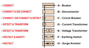
BUSBAR
BUSBAR (or bus, for short) – is a term we use for a main bar or conductor carrying an electric current to which many connections may be made.
Buses are merely convenient means of connecting switches and other equipment into various arrangements. The usual arrangement of connections in most substations permits working on almost any piece of equipment without interruption to incoming or outgoing feeders. In the switchyard or substation, buses are open to the air. Aluminum or copper conductors supported on porcelain insulators, carry the electric energy from point to point.
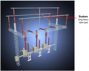
DISCONNECTS
DISCONNECT – is an easily removed piece of the actual conductor of a circuit. The purpose of disconnects is to isolate equipment. Disconnects are not used to interrupt circuits; they are no-load devices. A typical use of disconnects is to isolate a circuit breaker by installing one disconnect on either side of the circuit breaker (in series with the breaker). Operation of disconnects is one of the most important and responsible jobs of a power plant operator. One error in isolation of equipment, or the accidental grounding of the line equipment, can be a fatal mistake.
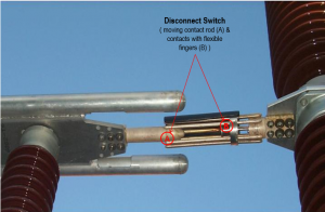
CIRCUIT BREAKER
CIRCUIT BREAKER – is used to interrupt circuits while current is flowing through them. The making and breaking of contacts in an Oil type circuit breaker are done under oil, this oil serves to quench the arc when the circuit is opened. The operation of the breaker is very rapid when opening. As with the transformer, the high voltage connections are made through bushings. Circuit breakers of this type are usually arranged for remote electrical control from a suitably located switchboard.
Some recently developed circuit breakers have no oil, but put out the arc by a blast of compressed air; these are called air circuit breakers. Another type encloses the contacts in a vacuum or a gas (sulfur hexafluoride, SF6) which tends to self maintain the arc.
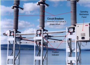
CURRENT TRANSFORMER
CURRENT TRANSFORMER – Current transformers are used with ammeters, wattmeters, power-factor meters, watt-hour meters, compensators, protective and regulating relays, and the trip coil of circuit breakers. One current transformer can be used to operate several instruments, provided that the combined burden does not exceed that for which the transformer is designed and compensated. The current transformer is connected directly in series with the line.
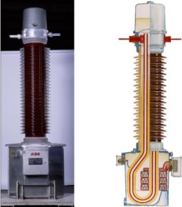
VOLTAGE TRANSFORMER
VOLTAGE TRANSFORMER – also known as a potential transformer, is used with volt-meters, wattmeters, watt-hour meters, power-factor meters, frequency meters, synchroscopes, and synchronizing apparatus, protective and regulating relays, and the no-voltage and over-voltage trip coils of automatic circuit breakers. One transformer can be used for several instruments at the same time if the total current taken by the instrument does not exceed that for which the transformer is designed and compensated. The ordinary voltage transformer is connected across the line, and the magnetic flux in the core depends upon the primary voltage
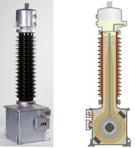
EARTHING SWITCH
EARTHING SWITCH – also known as ground disconnect, which is used to connect the equipment to a grid of electrical conductors buried in the earth on the station property. It is intended to protect people working on the grounded equipment. It does this by completing a circuit path, thereby reducing the voltage difference between the equipment and its surroundings. For safety reasons, it is important that ground disconnects and all associated connections have good contact and low resistance. It is also important that the protective ground not be accidentally removed, that is why all the earthing switches, disconnect switches, and circuit breakers are all interlocked to each other and proper/correct sequencing must be followed.
SURGE ARRESTOR
SURGE ARRESTOR – are devices used to provide the necessary path to ground for such surges, yet prevent any power current form following the surge. An ideal arrester must therefore have the following properties:
1. Ability to remove the surge energy from the line in a min. time.
2. High resistive to flow of power current.
3. A valve action automatically allows surge to pass and then close up so as not to permit power current to flow to the ground.
4. Always ready to perform.
5. Performance such that no system disturbances are introduced by its operation.
6. Economically feasible
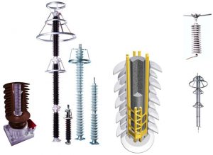
OVERHEAD GROUND WIRE – by a ground wire is meant a wire, generally of steel, supported from the top of transmission-line towers and solidly grounded at each tower. It is considered a preventive device, but it does not entirely prevent the formation of traveling waves on a line. Furthermore, those lines which are not equipped with ground wires will be subjected to disturbances that produce surges that must be allowed to escape to the ground, or the apparatus connected to the line must be strong enough to reflect or absorb these surges until they are entirely damped out.
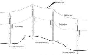
PREVENTIVE MAINTENANCE
At least once a year
At least once a month
At least once a year
At least once a month
At least once a year
CURRENT TRANSFORMER
At least once a month
At least once a year
Note: Never open a secondary winding of a CT while on service.
At least once a year
Note: Arrestors should never be touched unless completely disconnected from all live lines and equipment and effectively connected to the ground at the line side of the arrestor.
DIGSI 4 is configuration software for SIPROTEC 4 and SIPROTEC compact relays. We provide good content to learn DIGSI 4.
For DIGSI 4 Training Just leave a comment on this post or contact us for a reservation
For DIGSI 4 and DIGSI 5 Online training, contact us

MV and LV Switchgear Test Procedure (SIMPPRIME, SIVACON)
The aim of this document is a description of the responsibilities of the test procedure during all stages related to the switchboard. This guide direction is prepared for related stages to the pre-commissioning and commissioning of switchgear.
Part I, Pdf, 400 pages
Part II, pdf, 100 pages
To Download, contact us
This course contains the following topics:

Large or small, every industrial, commercial, and institutional organization needs to understand how to protect their investment in their electric power systems.
The task of the electrical unit protection is to detect electrical failures and inadmissible operation of the generator, generator bus bar, excitation system, generator transformer, and another existing transformer (Station transformer, unit auxiliary transformer) and disconnect faulty circuits with speed and certainly without interference healthy circuits.
An automatic synchronizing unit is furnished for connecting the generator unit to the grid via the generator circuit breaker. It is also possible to connect via the circuit breakers in the HV substation if the generator circuit breaker is already closed.
The universal transducers allow the measurement of all electrical quantities occurring in any network in a single unit. Especially in power plants and substations, transducers are used to isolate electrical signals and further process measured values.
The following PDF is the course on Protection, synchronization, and measurement system in the generation station. This course is based on the Siemens project.
Type: PDF
Page: 120
Size: 21 MB

Generator Transformer Protection System full diagram based on SIPROTEC Siemens Relays
The task of the electrical unit protection is to detect electrical failures and inadmissible operation of the generator, generator bus bar, excitation system, generator transformer, and another existing transformer (Station transformer, unit auxiliary transformer) and disconnect faulty circuits with speed and certainly without interference healthy circuits. The mechanical turbine and generator protection are independent of electrical protection. The generator protection and synchronizing cubicles will be delivered in fully wired and tested cubicles, ready for connection. Each subcase contains a complete protection device with DC/DC converter for power supply, Potential, and current transformers, an A/D converter, computer chips, a watchdog circuit, and trip relays.
A numerical protection system (NPS) shall mean the protection terminals wherein the analog to digital conversion of the input variables takes place immediately after the input transformers and all further processing of the resulting numerical signals shall be performed by microprocessors and controlled by programs. NPS shall include all features of conventional relays, protective devices, relay panels for generator, generator transformer, unit transformer, and station transformer
The following course contains the diagram of the Generator and Transformer protection based on SIPROTEC 4 SIEMENS IEDs. Please contact us for more info and get this course.


Siemens Protection Devices Limited (SPDL)
SPDL – Reyrolle Product Introduction
The history of Reyrolle with over 100 Years of Experience
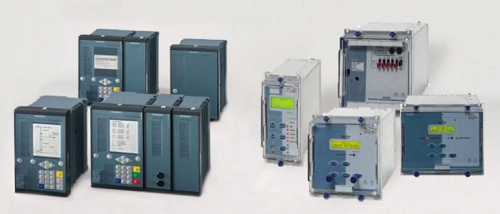
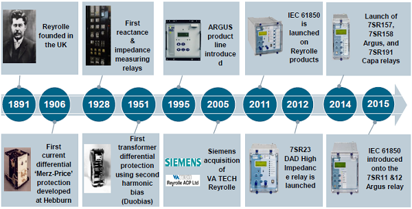
Reyrolle has been synonymous with electrical protection devices in the sectors of sub-transmission, distribution, and industrial applications for decades. Historically, Reyrolle relays, initially sold mainly in traditional markets, are now sold worldwide as part of the Siemens protection network.
Since its foundation, Reyrolle has been an innovation driver in product development – based on a strong focus on market, customer, and technology. Worldwide established brand names such as “Solkor” and “Argus” demonstrate this. But there is more: A wide range of Reyrolle products has determined technological firsts in the market.
The comprehensive range of Reyrolle products provides the total protection requirements of distribution markets – ranging from overcurrent protection via transformer protection and voltage control to a full spectrum of auxiliary and trip relays. The portfolio
includes many famous products such as “Argus”, “Duobias”, “Solkor”, “Rho”, etc.
To serve specific needs in industrial applications, a range of proven products such as “Argus overcurrent”, “Solkor line differential” and “Rho motor protection devices” is offered.
Through successive generations, Reyrolle numerical products have been developed to increase value to system operators.
This increase in value is the result of consistent development:
Siemens Protection Devices Limited (SPDL) Introduction – Portfolio Offering
Ease-of-use as a principle – our withdrawable product solutions allow flexible, easy operation through high user
friendliness.
One size fits all – the 4U housing height and the latest generation of numerical products features 1A/5A CT Input,
and some models are provided with universal DC supplies.
Learn once, know all – the new product generation provides a similar look and feels as earlier products. If Reyrolle numerical
devices have been previously used, there is a high consistency in both programming and interrogation.
With Reydisp Evolution, a comprehensive software support toolkit for relay setting, fault interrogation, and general
system information is provided. It is backward-compatible with all previous Reyrolle numerical devices.
.
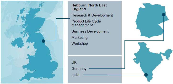
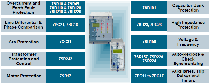
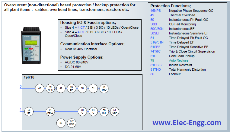
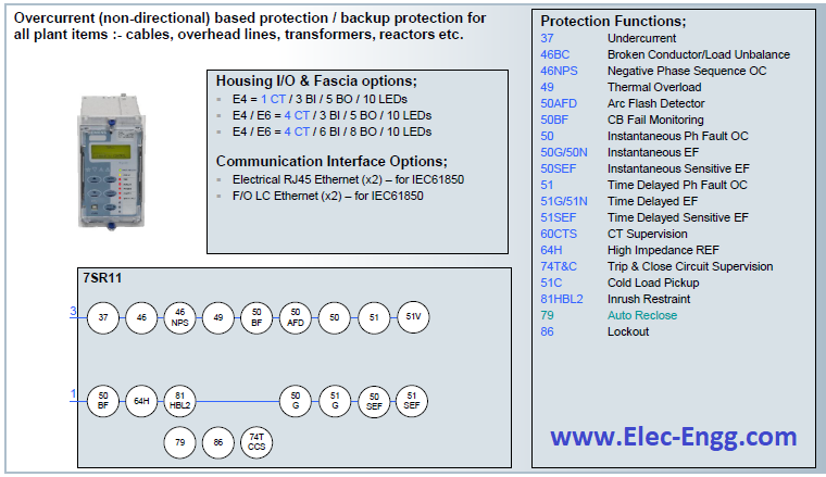
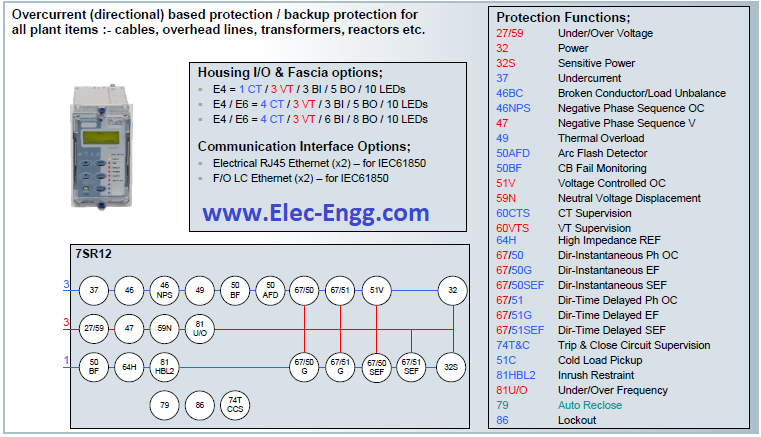
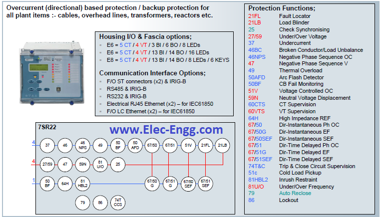
7SR22 (Argus) Overcurrent Protection; directional
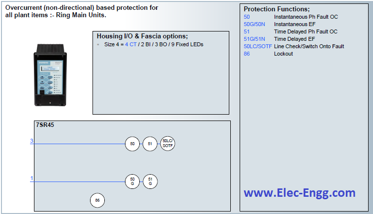
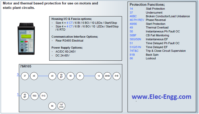
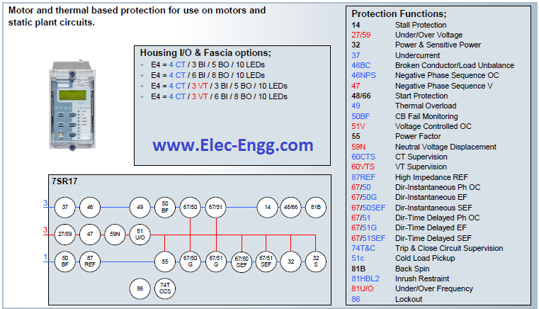
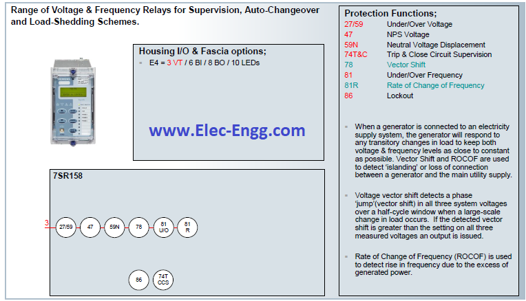
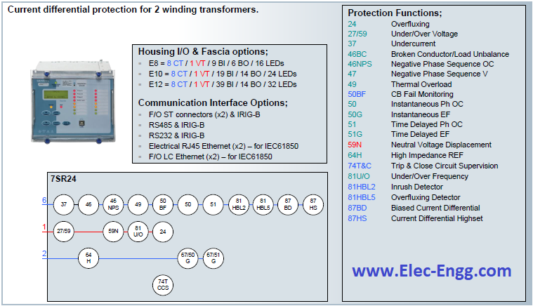

SIEMENS 7SR Virtual Relay

IEC 61850 library for Engineers
| {.pdf} | ⦁ | Time_Synch_IEC_61850_and_C37118_Harmonize. |
| {.pdf} | ⦁ | 615 series ANSI IEC 61850 Engineering Guide. |
| {.pdf} | ⦁ | 650 series IEC 61850 Communication Protocol Manual. |
| {.pdf} | ⦁ | 650 series IEC 61850 Communication Protocol Manual. |
| {.pdf} | ⦁ | 670 series 2.0 IEC IEC 61850 Edition 1 Communication Protocol Manual. |
| {.pdf} | ⦁ | 670 series 2.0 IEC IEC 61850 Edition 2 Communication Protocol Manual. |
| {.pdf} | ⦁ | 2013 IEC 61850 INTEROPERABILITY TEST Munich, Germany. |
| {.pdf} | ⦁ | 61850 easy. |
| {.pdf} | ⦁ | ABB AFS660 Switch High-availability Ethernet device based on new IEC-standard redundancy protocols PRP/HSR. |
| {.pdf} | ⦁ | ABB AFS660 Switch High-availability Ethernet device based on new IEC-standard redundancy protocols PRP/HSR. |
| {.pdf} | ⦁ | ABB is implementing the first commercial installation of IEC 61850-9-2 LE process-bus technology. |
| {.pdf} | ⦁ | ABB review Special Report IEC 61850. |
| {.pdf} | ⦁ | Advanced protection and control IEDs from ABB. |
| {.pdf} | ⦁ | AGILE DIGITAL SUBSTATIONS The complete guide. |
| {.pdf} | ⦁ | Analysis and implementation of the IEC 61850 standard. |
| {.pdf} | ⦁ | Application Considerations of IEC 61850/UCA 2 for Substation Ethernet Local Area Network Communication for Protection and Control. |
| {.pdf} | ⦁ | Applications of IEC 61850 Standard to Protection Schemes. |
| {.pdf} | ⦁ | Applications of Phasor Measurement Units. |
| {.pdf} | ⦁ | Applications of PMU measurements in the Belgian electrical grid. |
| {.pdf} | ⦁ | The Application-View Model of the International Standard IEC 61850. |
| {.pdf} | ⦁ | Approach to optimized process Bus architectures. |
| {.pdf} | ⦁ | Approach to optimized process Bus architectures. |
| {.pdf} | ⦁ | Automation at Protection Speeds: IEC 61850 GOOSE Messaging as a Reliable, High-Speed Alternative to Serial Communications. |
| {.pdf} | ⦁ | The Building Blocks of a Data-Aware Transport Network: Deploying Viable Ethernet and Virtual Wire Services via Multiservice ADMs. |
| {.pdf} | ⦁ | Calibration System for Electronic Instrument Transformers With Digital Output. |
| {.pdf} | ⦁ | Challenges and Integration of PV and Wind Energy Facilities from a Smart Grid Point of View. |
| {.pdf} | ⦁ | Challenges and Lessons Learned from Commissioning an IEC 61850-90-5 Based Synchrophasor System. |
| {.pdf} | ⦁ | Colombian electrical sector adopting high redundancy communication design on a new HV substation
⦁ COMMON REQUIREMENTS FOR ELECTRIC POWER EQUIPMENT. ⦁ Communication in Power application. ⦁ Communication Protocols and Networks for Power Systems- Current Status and Future Trends. ⦁ Communications network solutions for smart grids. ⦁ The concept of IEC 61850. ⦁ CT Standard. ⦁ D2-01_07_Meeting requirements in an IEC 61850 station bus SAS. ⦁ Data transport network. ⦁ Dealing with Packet Delay Variation in IEEE 1588 Synchronization Using a Sample-Mode Filter. ⦁ Design and Implementation of Packet Analyzer for IEC 61850 Communication Networks in Smart Grid. ⦁ Design and Performance Testing of a Multivendor IEC61850–9-2 Process Bus Based Protection Scheme. ⦁ Design, Development, and Commissioning of a Supervisory Control and Data Acquisition (SCADA) Laboratory for Research and Training. ⦁ DEVELOPING PROTECTIVE RELAY FACEPLATES. ⦁ Developing Real-Time PMU Applications for Smart Transmission Grids. ⦁ Development of IEC61850 Based Substation Engineering Tools with IEC61850 Schema Library. ⦁ Differential Protection RET 54_/Diff6T function Application and Setting Guide. ⦁ Digital umspannwerk. ⦁ Digitalization in Transmission and Distribution. ⦁ Direct Evaluation of IEC 61850-9-2 Process Bus Network Performance. ⦁ Distributed busbar protection REB500 including line and transformer protection Product Guide. ⦁ Distributed Multifunction Fault Recorder. ⦁ A Distributed PMU for Electrical Substations With Wireless Redundant Process Bus. ⦁ Duplicate and Circulating Frames Discard Methods for PRP and HSR (IEC62439-3). ⦁ Dynamic Testing of an IEC 61850 Based 110 kV Smart Substation Solution. ⦁ EC 61850 for Substations. ⦁ ECT Evaluation by an Error Measurement System According to IEC 60044-8 and 61850-9-2. ⦁ Efficient Energy Automation with the IEC 61850 Standard Application Examples Energy Automation. ⦁ Emerging Applications of Synchronous Ethernet in Telecommunication Networks. ⦁ Enabling digital substations. ⦁ Energy Management of Internet Data Centers in Smart Grid. ⦁ Engineering Perspective on IEC 61850. ⦁ Enhanced Engineering process SCL example. ⦁ Enhanced Engineering process SCL Files. ⦁ ERL 61850 IED Configurator. ⦁ ERL 61850 IED Configurator. ⦁ Ethernet & IEC 61850 Concepts, Implementation, Commissioning. ⦁ Ethernet in SAS. ⦁ Ethernet in SAS. ⦁ Ethernet in Substation Automation Applications – Issues and Requirements. ⦁ Ethernet Module EN100 for IEC 61850 with electrical/optical 100 MBit Interface Application Examples. ⦁ Ethernet Networks Redundancy With Focus On IEC 61850 Applications. ⦁ ETHERNET NETWORKS REDUNDANCY WITH FOCUS ON IEC 61850 APPLICATIONS. ⦁ Ethernet-Based Public Communication Services: Challenge and Opportunity. ⦁ Evaluation of IEC 61850-9-2 Samples Loss on Total Vector Error of an Estimated Phasor. ⦁ The Evaluation of Phasor Measurement Units and Their Dynamic Behavior Analysis. ⦁ Evaluation of Time Gateways for Synchronization of Substation Automation Systems. ⦁ Executive Summary (Introduction to MMS. ⦁ Feeder Protection and Control REF615 Application Manual. ⦁ Focus on the application – IEC 61850 experience with the third-party system configuration tool. ⦁ Generic IEC61850 IED Connectivity Package User‘s Guide. ⦁ Get on the digital bus to SA. ⦁ GOOSE AIR. ⦁ GOOSE Configuration Example. ⦁ Goose messages for automated testing: 765 kV transmission network. ⦁ Goose Messaging Determining its potential in a real case. ⦁ GOOSE IEC 61850 Test System. ⦁ GPS and IEEE 1588 synchronization for the measurement of synchrophasors in electric power systems. ⦁ Grid Automation REC615 and RER615 IEC 61850 Engineering Guide. ⦁ HardFiber. ⦁ Hidden Challenges in the Implementation of 61850 in Larger Substation Automation Projects. ⦁ IEC60076. ⦁ iec61850-8-1{ed1.0}en-2004. ⦁ IEC61850 Based Process Bus Protection Solution for Remote Located Power Transformers. ⦁ IEC61850 Modeling for Switch Management. ⦁ IEC 60870-5-101/104 Slave Technical. ⦁ IEC 60870-5-103 Communication Protocol Manual. ⦁ IEC 61400-25-2. ⦁ IEC 61850-3 and IEEE 1588. ⦁ IEC 61850-7-420 IEC 61850 Part 7-420 DER Logical Nodes. ⦁ IEC 61850-9-2 Based Process Bus. ⦁ IEC 61850-9-2 Process Bus and Its Impact on Power System Protection and Control Reliability. ⦁ IEC 61850-9-2 Process Bus Communication Interface for Light Weight Merging Unit Testing Environment. ⦁ IEC 61850 – Communication networks and systems in substations. ⦁ IEC 61850 – More Than Just GOOSE: A Case Study of Modernizing Substations in Namibia. ⦁ IEC 61850 Process Bus – It is Real!. ⦁ IEC 61850: COMMUNICATION NETWORKS AND SYSTEMS IN SUBSTATIONS. ⦁ IEC 61850 and Measurements. ⦁ IEC 61850 -Communication Networks and Systems in Substations: ⦁ Ethernet Networks Redundancy With Focus On IEC 61850 Applications. ⦁ ETHERNET NETWORKS REDUNDANCY WITH FOCUS ON IEC 61850 APPLICATIONS. ⦁ Ethernet-Based Public Communication Services: Challenge and Opportunity. ⦁ Evaluation of IEC 61850-9-2 Samples Loss on Total Vector Error of an Estimated Phasor. ⦁ The Evaluation of Phasor Measurement Units and Their Dynamic Behavior Analysis. ⦁ Evaluation of Time Gateways for Synchronization of Substation Automation Systems. ⦁ Executive Summary (Introduction to MMS. ⦁ Feeder Protection and Control REF615 Application Manual. ⦁ Focus on the application – IEC 61850 experience with the third-party system configuration tool. ⦁ Generic IEC61850 IED Connectivity Package User‘s Guide. ⦁ Get on the digital bus to SA. ⦁ GOOSE AIR. ⦁ GOOSE Configuration Example. ⦁ Goose messages for automated testing: 765 kV transmission network. ⦁ Goose Messaging Determining its potential in a real case. ⦁ GOOSE IEC 61850 Test System. ⦁ GPS and IEEE 1588 synchronization for the measurement of synchrophasors in electric power systems. ⦁ Grid Automation REC615 and RER615 IEC 61850 Engineering Guide. ⦁ HardFiber. ⦁ Hidden Challenges in the Implementation of 61850 in Larger Substation Automation Projects. ⦁ IEC60076. ⦁ iec61850-8-1{ed1.0}en-2004. ⦁ IEC61850 Based Process Bus Protection Solution for Remote Located Power Transformers. ⦁ IEC61850 Modeling for Switch Management. ⦁ IEC 60870-5-101/104 Slave Technical. ⦁ IEC 60870-5-103 Communication Protocol Manual. ⦁ IEC 61400-25-2. ⦁ IEC 61850-3 and IEEE 1588. ⦁ IEC 61850-7-420 IEC 61850 Part 7-420 DER Logical Nodes. ⦁ IEC 61850-9-2 Based Process Bus. ⦁ IEC 61850-9-2 Process Bus and Its Impact on Power System Protection and Control Reliability. ⦁ IEC 61850-9-2 Process Bus Communication Interface for Light Weight Merging Unit Testing Environment. ⦁ IEC 61850 – Communication networks and systems in substations. ⦁ IEC 61850 – More Than Just GOOSE: A Case Study of Modernizing Substations in Namibia. ⦁ IEC 61850 Process Bus – It is Real!. ⦁ IEC 61850: COMMUNICATION NETWORKS AND SYSTEMS IN SUBSTATIONS. ⦁ IEC 61850 and Measurements. ⦁ IEC 61850 -Communication Networks and Systems in Substations: An Overview of Computer Science. ⦁ IEC 61850 driver FAQ. ⦁ IEC 61850 Enabled Automatic Bus Transfer Scheme for Primary Distribution Substations. ⦁ IEC 61850 General. ⦁ IEC 61850 GOOSE and IEEE C37.118 Synchrophasors Used for Wide-Area Monitoring and Control, SPS, RAS, and Load and Generation Management. ⦁ IEC 61850 Goose applications to distribution protection schemes. ⦁ IEC 61850 Goose applications to distribution protection schemes. ⦁ IEC 61850 MMS Client Driver Help. ⦁ IEC 61850 Model Expansion Toward Distributed Fault Localization, Isolation, and Supply Restoration. ⦁ IEC 61850 Process Bus – It is Real!. ⦁ IEC 61850 PROCESS CONNECTION – A SMART SOLUTION TO CONNECT THE PRIMARY EQUIPMENT TO THE SUBSTATION AUTOMATION SYSTEM. ⦁ IEC 61850 Protocol API User Manual. ⦁ IEC 61850 Qualifications. ⦁ IEC 61850 standard for SA. ⦁ The IEC 61850 standard for SA. ⦁ IEC 61850 standard for SA. ⦁ IEC 61850 Substation Configuration Language and Its Impact on the Engineering of Distribution Substation Systems. ⦁ IEC 61850 System Configurator. ⦁ IEC 61850 System Configurator. ⦁ IEC 61850 Technical Overview. ⦁ IEC 61850/61400 Model Designer. ⦁ IEC 61850: Role of Conformance Testing in Successful Integration. ⦁ IEC 61850: WHAT YOU NEED TO KNOW ABOUT FUNCTIONALITY AND PRACTICAL IMPLEMENTATION. ⦁ IEC 61850-Based Feeder Terminal Unit Modeling and Mapping to IEC 60870-5-104. ⦁ IEC 61850-Based Information Model and Configuration Description of Communication Network in Substation Automation. ⦁ IEC 62357: TC57 Architecture Part 1: Reference Architecture for Power System Information Exchange. ⦁ IEC 62439 PRP: Bumpless Recovery for Highly Available, Hard Real-Time Industrial Networks. ⦁ IEC Smart Grid Standardization Roadmap. ⦁ IED Configuration Guidelines. ⦁ IEEE-1588 Standard for a Precision Clock Synchronization Protocol for Networked Measurement and Control Systems. ⦁ IEEE 802.1AS and IEEE 1588. ⦁ IEEE 802.3ba 40 and100 Gigabit Ethernet Architecture. ⦁ IEEE 1547.2 IEEE Application Guide for IEEE Std 1547™, IEEE Standard for Interconnecting Distributed Resources with Electric Power Systems. ⦁ IEEE 1547.3 IEEE Guide for Monitoring, Information Exchange, and Control of Distributed Resources Interconnected with Electric Power Systems. ⦁ IEEE 1547.4 IEEE Guide for Design, Operation, and Integration of Distributed Resource Island Systems with Electric Power Systems. ⦁ IEEE 1547.6 IEEE Recommended Practice for Interconnecting Distributed Resources with Electric Power Systems Distribution Secondary Networks. ⦁ IEEE 1588. ⦁ IEEE 1588 Precision Time Protocol Time Synchronization Performance. ⦁ IEEE 1588 Precision Time Synchronization Solution for Electric Utilities. ⦁ IEEE 1588 Version 2. ⦁ IEEE 1615 IEEE Recommended Practice for Network Communication in Electric Power Substations. ⦁ IEEE Application Guide for IEEE Std 1547™, IEEE Standard for Interconnecting Distributed Resources with Electric Power Systems.” |
| {.pdf} | ⦁ | IEEE c37.118.1 IEEE Standard for Synchrophasor Measurements for Power Systems. |
| {.pdf} | ⦁ | IEEE c37.118.2 2011 IEEE Standard for Synchrophasor Data Transfer for Power Systems. |
| {.pdf} | ⦁ | IEEE Recommended Practice for Network Communication in Electric Power Substations. |
| {.pdf} | ⦁ | IEEE Standard for a Precision Clock Synchronization Protocol for Networked Measurement and Control Systems. |
| {.pdf} | ⦁ | IEEE Standard for Electric Power Systems Communications— Distributed Network Protocol (DNP3). |
| {.pdf} | ⦁ | IEEE Standard for Ethernet. |
| {.pdf} | ⦁ | IEEE Standard for Ethernet. |
| {.pdf} | ⦁ | IEEE Standard for Ethernet Amendment 1: Physical Layer Specifications and Management Parameters for Extended Ethernet Passive Optical Networks. |
| {.pdf} | ⦁ | IEEE Standard for Information technology— Telecommunications and information exchange between systems Local and metropolitan area networks— Specific requirements Part 17: Resilient packet ring (RPR) access method and physical layer specifications. |
| {.pdf} | ⦁ | IEEE Standard for Service Interoperability in Ethernet Passive Optical Networks (SIEPON). |
| {.pdf} | ⦁ | IEEE Standard for Synchrophasor Data Transfer for Power Systems. |
| {.pdf} | ⦁ | IEEE Standard for Synchrophasor Measurements for Power Systems. |
| {.pdf} | ⦁ | IEEE Standard Profile for Use of IEEE 1588™ Precision Time Protocol in Power System Applications. |
| {.pdf} | ⦁ | IEEE Std 802.1. |
| {.pdf} | ⦁ | Impact of IEC 61850-9-2 Standard-Based Process Bus on the Operating Performance of Protection IEDS: Comparative Study. |
| {.pdf} | ⦁ | IMPLEMENTATION GUIDELINE FOR DIGITAL INTERFACE TO INSTRUMENT TRANSFORMERS USING IEC 61850-9-2. |
| {.pdf} | ⦁ | An Implementation of FTTH based Home Gateway Supporting Various Services. |
| {.pdf} | ⦁ | Implementing New Generation Protective Relay Schemes based on IEC61850 Standard for Substation Communication in the Eskom 765kV Transmission Network. |
| {.pdf} | ⦁ | Implementing Vehicle-to-Grid (V2G) Technology With IEC 61850-7-420. |
| {.pdf} | ⦁ | Industrial & Plant Communication. |
| {.pdf} | ⦁ | Industrial automation systems Manufacturing Message Specification. |
| {.pdf} | ⦁ | Industrial Communication. |
| {.pdf} | ⦁ | INDUSTRIAL INFORMATION TECHNOLOGY. |
| {.pdf} | ⦁ | Installation and commissioning manual Line distance protection IED REL 670. |
| {.pdf} | ⦁ | INSTRUCTION MANUAL DISTANCE RELAY WITH INTEGRAL DIGITAL COMMUNICATION GRZ100. |
| {.pdf} | ⦁ | INSTRUCTION MANUAL TRANSFORMER PROTECTION RELAY GRT100. |
| {.pdf} | ⦁ | The Integrated Energy and Communication Systems Architecture. |
| {.pdf} | ⦁ | AN INTEGRATED PMU AND PROTECTION SCHEME FOR POWER SYSTEMS. |
| {.pdf} | ⦁ | Integration of a New Standard. |
| {.pdf} | ⦁ | Integration of IEC 61850 GSE and Sampled Value Services to Reduce Substation Wiring. |
| {.pdf} | ⦁ | Integration of IEC 61850 GSE and Sampled Value Services to Reduce Substation Wiring. |
| {.pdf} | ⦁ | INTERNSHIP REPORT USE OF IEC 61850 FOR ASSET MANAGEMENT IN LOW VOLTAGE MICROGRIDS. |
| {.pdf} | ⦁ | Interoperability and Performance Analysis of IEC61850 Based Substation Protection System. |
| {.pdf} | ⦁ | Interoperability Requirements for IEC 61850 System Configuration Tools. |
| {.pdf} | ⦁ | Introduction and Overview of IEC 61850 Configuration and Diagnostics. |
| {.pdf} | ⦁ | IP and Ethernet Communication Technologies and Topologies for IED networks. |
| {.pdf} | ⦁ | Issues and Approaches on Extending Ethernet Beyond LANs. |
| {.pdf} | ⦁ | Kalki SCL Manager. |
| {.pdf} | ⦁ | Laboratory Investigation of IEC 61850-9-2-Based Busbar and Distance Relaying With Corrective Measure for Sampled Value Loss/Delay. |
| {.pdf} | ⦁ | Large Scale Grid Integration of Renewable Energy Sources – Way Forward. |
| {.pdf} | ⦁ | Leading the way to Digital Substations. |
| {.pdf} | ⦁ | Lecture 5a Substation Automation Systems. |
| {.pdf} | ⦁ | LINE PROTECTION TESTS USING PROCESS BUS IEC 61850-9-2 WITH NETWORK LOADING. |
| {.pdf} | ⦁ | Logical nodes. |
| {.pdf} | ⦁ | MAGNUM 6K FAMILY OF SWITCHES. |
| {.pdf} | ⦁ | Magnum 6KL Managed Edge Switch. |
| {.pdf} | ⦁ | Memory Requirements Analysis for PRP and HSR Hardware Implementations on FPGAs. |
| {.pdf} | ⦁ | MiCOM Px4x-92LE Technical Manual IEC 61850-9-2LE Interface. |
| {.pdf} | ⦁ | MiCOM Px4x-92LE Technical Manual IEC 61850-9-2LE Interface. |
| {.pdf} | ⦁ | MIGRATION PATHS FOR IEC 61850 SUBSTATION COMMUNICATION NETWORKS TOWARDS SUPERB REDUNDANCY BASED ON HYBRID PRP AND HSR TOPOLOGIES. |
| {.pdf} | ⦁ | Model Implementation Conformance Statement (MICS) for IEC 61850 for the SEL Real-Time Automation Controllers. |
| {.pdf} | ⦁ | Model Implementation Conformance Statement for the IEC 61850 interface in SEL-351A. |
| {.pdf} | ⦁ | Model Implementation Conformance Statement for the IEC 61850 interface in SEL-351S. |
| {.pdf} | ⦁ | Model Implementation Conformance Statement for the IEC 61850 interface in SEL-2411. |
| {.pdf} | ⦁ | Model Implementation Conformance Statement for the IEC 61850 interface in SEL-2440. |
| {.pdf} | ⦁ | Modeling and (Co-)simulation of power systems, controls, and components for analyzing complex energy systems. |
| {.pdf} | ⦁ | Modeling and Simulation for Performance Evaluation of IEC61850-Based Substation Communication Systems. |
| {.pdf} | ⦁ | The move to IEC61850 what and when will it be delivered?. |
| {.pdf} | ⦁ | MU. |
| {.pdf} | ⦁ | MU320 Merging Unit. |
| {.pdf} | ⦁ | MU Agile AMU Technical Manual Analogue Merging Unit. |
| {.pdf} | ⦁ | Network Interactions and Performance of a Multifunction IEC 61850 Process Bus. |
| {.pdf} | ⦁ | A network scheme for process bus in smart substations without using external synchronization. |
| {.pdf} | ⦁ | A New IED With PMU Functionalities For Electrical Substations. |
| {.pdf} | ⦁ | Next-generation substations. |
| {.pdf} | ⦁ | Non-conventional instrument transformers Advanced GIS substations with IEC 61850-9-2 LE process bus. |
| {.pdf} | ⦁ | A Novel Communication Network for Three-Level Wide Area Protection System. |
| {.pdf} | ⦁ | Object Modeling of Data and DataSets in the International Standard IEC 61850. |
| {.pdf} | ⦁ | Offprint of an article published in PAC World, Fall 2008 Standard IEC 61850 – Network Redundancy using IEC 62439. |
| {.pdf} | ⦁ | On the Use of IEEE 1588 in Existing IEC 61850-Based SASs: Current Behavior and Future Challenges. |
| {.pdf} | ⦁ | One-Way Delay and PTP (IEEE 1588v2) Test Applications. |
| {.pdf} | ⦁ | Optimal Integration of Disparate C37.118 PMUs in Wide-Area PSS With Electromagnetic Transients. |
| {.pdf} | ⦁ | Overview of IEC 61850. |
| {.pdf} | ⦁ | Overview of IEC 61850. |
| {.pdf} | ⦁ | Packet Tracer Network Simulator. |
| {.pdf} | ⦁ | The Parallel Redundancy Protocol for Industrial IP Networks. |
| {.pdf} | ⦁ | Performance Analysis of IEC 61850 Sampled Value Process Bus Networks. |
| {.pdf} | ⦁ | Performance assessment of an IEC 61850-9-2 based protection scheme for the mesh corner of a 400kV transmission substation. |
| {.pdf} | ⦁ | Performance Evaluation of Time-critical Communication Networks for Smart Grids based on IEC 61850. |
| {.pdf} | ⦁ | Performance of IEC 61850-9-2 Process Bus and Corrective Measure for Digital Relaying. |
| {.pdf} | ⦁ | Phasor measurement based on IEC 61850-9-2 and Kalman–Filtering. |
| {.pdf} | ⦁ | Plan Ahead for Substation Automation. |
| {.pdf} | ⦁ | Plc-based SA and SCADA. |
| {.pdf} | ⦁ | Plug-in rapid-wire integrated. |
| {.pdf} | ⦁ | pmu. |
| {.pdf} | ⦁ | A PMU for the Measurement of Synchronized Harmonic Phasors in Three-Phase Distribution Networks. |
| {.pdf} | ⦁ | The PMU Interface using IEC 61850. |
| {.pdf} | ⦁ | PMU Interoperability, Steady-State, and Dynamic Performance Tests. |
| {.pdf} | ⦁ | PMU-based Voltage Instability Detection through Linear Regression. |
| {.pdf} | ⦁ | Power network telecommunication PowerLink – power line carrier system. |
| {.pdf} | ⦁ | Power network telecommunication PowerLink – technical data. |
| {.pdf} | ⦁ | Power network telecommunication SWT 3000 Teleprotection. |
| {.pdf} | ⦁ | The power of IEC 61850. |
| {.pdf} | ⦁ | The power of IEC 61850. |
| {.pdf} | ⦁ | POWER SYSTEM MONITORING. |
| {.pdf} | ⦁ | Power Systems Communications. |
| {.pdf} | ⦁ | a practical application primer for protection engineers. |
| {.pdf} | ⦁ | Practical Applications of Ethernet in Substations and Industrial Facilities. |
| {.pdf} | ⦁ | Practical Considerations for Ethernet Networking Within Substations. |
| {.pdf} | ⦁ | Practical Experience with IEEE 1588 High Precision Time Synchronization in Electrical Substation based on IEC 61850 Process Bus. |
| {.pdf} | ⦁ | Precision Clock Synchronization. |
| {.pdf} | ⦁ | Precision Time Protocol. |
| {.pdf} | ⦁ | PROPAGATION AND INTERACTION OF ETHERNET PACKETS WITH IEC 61850 SAMPLED VALUES IN POWER UTILITY COMMUNICATION NETWORKS. |
| {.pdf} | ⦁ | Protection and Control System Upgrade Based on IEC- 61850 and PRP. |
| {.pdf} | ⦁ | Protocol Implementation Conformance Statement (PICS) for IEC 61850 for the SEL Real-Time Automation Controllers. |
| {.pdf} | ⦁ | PRP and HSR for High Availability Networks in Power Utility Automation: A Method for Redundant Frames Discarding. |
| {.pdf} | ⦁ | PRP and HSR Version 1 (IEC 62439-3 Ed.2), Improvements, and a Prototype Implementation. |
| {.pdf} | ⦁ | The Real-Time Publisher/Subscriber Communication Model for Distributed Substation Systems. |
| {.pdf} | ⦁ | Reason RT411 Technical Manual Time Signal Distributor. |
| {.pdf} | ⦁ | Redundancy in Substation LANs with the Rapid Spanning Tree Protocol (IEEE 802.1w). |
| {.pdf} | ⦁ | Reliable data networks for electric power systems. |
| {.pdf} | ⦁ | Requirements for Ethernet Networks in Substation Automation. |
| {.pdf} | ⦁ | Resilience technologies in Ethernet. |
| {.pdf} | ⦁ | ROLE OF PHASOR MEASUREMENT UNIT (PMU) IN WIDE-AREA MONITORING AND CONTROL. |
| {.pdf} | ⦁ | SA Hand Book. |
| {.pdf} | ⦁ | SAM600 process bus. |
| {.pdf} | ⦁ | The SAM600 process bus IO system integrates conventional instrument transformers into modern, IEC 61850-9-2
⦁ process bus substation automation, protection, and control systems. |
| {.pdf} | ⦁ | Sampled Values. |
| {.pdf} | ⦁ | SAS Application pictures. |
| {.pdf} | ⦁ | SCADA and IP. |
| {.pdf} | ⦁ | SCADA Systems: Challenges for Forensic Investigators. |
| {.pdf} | ⦁ | Seamless redundancy. |
| {.pdf} | ⦁ | Selecting, Designing, and Installing Modern Data Networks in Electrical Substations. |
| {.pdf} | ⦁ | Selection Guide / Ethernet Switches. |
| {.pdf} | ⦁ | Sepam Ethernet Guide. |
| {.pdf} | ⦁ | Sepam IEC 61850 communication. |
| {.pdf} | ⦁ | SICAM A8000 Serie CP-8000 Master Modul mit I/O. |
| {.pdf} | ⦁ | SICAM A8000 Series. |
| {.pdf} | ⦁ | SICAM A8000 Series Wherever energy flows Protection Technology / Substation Automation / Power Quality and Measurements. |
| {.pdf} | ⦁ | SICAM A8000 Series CP-8000, CP-8021, CP-8022 User Manual. |
| {.pdf} | ⦁ | SICAM A8000 Series Operation, telecontrol, and automation in the smallest spaces. |
| {.pdf} | ⦁ | Simulation and testing of the over-current protection system based on IEC 61850 Process-Buses and dynamic estimator. |
| {.pdf} | ⦁ | Simulation of Parallel Redundant WLAN with OPNET. |
| {.pdf} | ⦁ | SINEAX CAM Parameterization of IEC61850 bus card. |
| {.pdf} | ⦁ | SIPROTEC 4, SIPROTEC easy, SIPROTEC 600 Series, Communication, Accessories. |
| {.pdf} | ⦁ | SIPROTEC 5 Communication protocol IEC 60870-5-103. |
| {.pdf} | ⦁ | SIPROTEC 5 Communication Protocol IEC 60870-5-104. |
| {.pdf} | ⦁ | SIPROTEC 5 Communication protocol IEC 61850. |
| {.pdf} | ⦁ | SIPROTEC 5 Modbus. |
| {.pdf} | ⦁ | SIPROTEC 5 Process Bus. |
| {.pdf} | ⦁ | SIPROTEC 5Communication protocol DNP3. |
| {.pdf} | ⦁ | SIPROTEC 7SC805. |
| {.pdf} | ⦁ | SIPROTECMerging Unit 6MU805 V4.01 Manual. |
| {.pdf} | ⦁ | SMART GRID COMMUNICATIONS AND MEASUREMENT TECHNOLOGY. |
| {.pdf} | ⦁ | smart grids. |
| {.pdf} | ⦁ | The Smart Substatiion usiing IIEC 61850 Ediitiion 2. |
| {.pdf} | ⦁ | Solutions for Digital Substation. |
| {.pdf} | ⦁ | SOLVING ELECTRICAL SUBSTATION TIMING PROBLEMS. |
| {.pdf} | ⦁ | Stand Alone Merging Unit User Guide MGU010000. |
| {.pdf} | ⦁ | A Study on GOOSE Communication based on lEC61850 using MMS Ease Lite. |
| {.pdf} | ⦁ | Substation Automation Process Bus. |
| {.pdf} | ⦁ | Substation Automation Systems. |
| {.pdf} | ⦁ | A Survey of Communication Network Paradigms for Substation Automation. |
| {.pdf} | ⦁ | A Survey of Ethernet LAN Security. |
| {.pdf} | ⦁ | SWITCHGEAR OPTIMIZATION USING IEC 61850-9-2. |
| {.pdf} | ⦁ | Switchgear Optimization Using IEC 61850-9-2 and Non-Conventional Measurements. |
| {.pdf} | ⦁ | Synchronized Phasor Measurements and Their Applications. |
| {.pdf} | ⦁ | Synchrophasor Standards Development – IEEE C37.118 & IEC 61850. |
| {.pdf} | ⦁ | System 800xA IEC 61850 Connect Configuration. |
| {.pdf} | ⦁ | System 800xA IEC 61850 Engineering Workflow. |
| {.pdf} | ⦁ | System Engineer Configures IEC 61850 Gateway to DNP3 Substation. |
| {.pdf} | ⦁ | System-Level Tests of Transformer Differential Protection Using an IEC 61850 Process Bus. |
| {.pdf} | ⦁ | TCP/IP Protocol Suite. |
| {.pdf} | ⦁ | Technical Requirements for DER Integration Architectures. |
| {.pdf} | ⦁ | Teleprotection over an IP/MPLS Network. |
| {.pdf} | ⦁ | Testing a SIPROTEC GOOSE bus protection scheme using an OMICRON CMC. |
| {.pdf} | ⦁ | Time Signal Distributor. |
| {.pdf} | ⦁ | Time Signal Distributor. |
| {.pdf} | ⦁ | Time Synchronization (IEEE 1588) and Seamless Communication Redundancy (IEC 62439-3) Techniques for Smart Grid Substations. |
| {.pdf} | ⦁ | Time Synchronized Low-Voltage Measurements for Smart Grids. |
| {.pdf} | ⦁ | Towards Implementation of IEC 61850 GOOSE Messaging in Event-Driven IEC 61499 Environment. |
| {.pdf} | ⦁ | Traffic Generation of IEC 61850 Sampled Values. |
| {.pdf} | ⦁ | Transforming Critical Communications Networks for Substation Automation Communications network infrastructure requirements and architectures. |
| {.pdf} | ⦁ | Two Improvements Related to Overcurrent Functions for Bus Protection in Distribution Systems. |
| {.pdf} | ⦁ | Use of IEEE 1588–2008 for a Sampled Value Process Bus in Transmission Substations. |
| {.pdf} | ⦁ | Use of Precision Time Protocol to Synchronize Sampled-Value Process Buses. |
| {.pdf} | ⦁ | User Experiences Implementing IEC61850 in Intelligent Electronic Devices. |
| {.pdf} | ⦁ | A user-friendly implementation of IEC 61850 in a new generation of protection and control devices. |
| {.pdf} | ⦁ | Using OPNET to Model and Evaluate the MU Performance Based on IEC 61850-9-2LE. |
| {.pdf} | ⦁ | Utilization of GOOSE in MV Substation. |
| {.pdf} | ⦁ | Utilizing IEC 61850, Ethernet, and IP Standards for Integrated Substation Communications. |
| {.pdf} | ⦁ | VAMP RELAYS IEC 61850 interface Configuration instructions. |
| {.pdf} | ⦁ | The Virginia Tech Calibration System. |
| {.pdf} | ⦁ | Virtual Power Plant for Grid Services using IEC 61850. |
| {.pdf} | ⦁ | VSE 006 IEC 61850 interface module. |
| {.pdf} | ⦁ | VSE 006 IEC 61850 interface module Configuration instructions. |
| {.pdf} | ⦁ | A Web-Based Remote Access Laboratory Using SCADA. |
| {.pdf} | ⦁ | What Is IEC 61850?. |
| {.pdf} | ⦁ | What Protection Engineers Need to Know About Networking. |
| {.pdf} | ⦁ | White Paper on Standards for DER Communications Using IEC 61850. |
| {.pdf} | ⦁ | Wide area voltage protection. |
| {.pdf} | ⦁ | Wide-Area Ethernet Network Configuration for System Protection Messaging. |
| {.pdf} | ⦁ | Wide-Area Ethernet Network Configuration for System Protection Messaging. |
| {.pdf} | ⦁ | Wide-Area Protection and Power System Utilization. |
| {.pdf} | ⦁ | (2003). “Communication networks and systems in substations – Part 1: Introduction and overview.” |
| {.pdf} | ⦁ | (2003). “Communication networks and systems in substations – Part 2: Glossary.” |
| {.pdf} | ⦁ | (2003). “Communication networks and systems in substations – Part 3: General requirements.” |
| {.pdf} | ⦁ | (2003). “Communication networks and systems in substations – Part 4: System and project management.” |
| {.pdf} | ⦁ | (2003). “Communication networks and systems in substations – Part 5: Communication requirements for functions and device models.” |
| {.pdf} | ⦁ | (2003). “COMMUNICATION NETWORKS AND SYSTEMS IN SUBSTATIONS Part 10: Conformance Testing.” |
| {.pdf} | ⦁ | (2003). “IEEE Standard Test Method for Use in the Evaluation of Message Communications Between Intelligent Electronic Devices in an Integrated Substation Protection, Control, and Data Acquisition System.” |
| {.pdf} | ⦁ | (2005). “Communication networks and systems in substations – Part 7-3: Basic communication structure for substation and feeder equipment – Common data classes.” |
| {.pdf} | ⦁ | (2005). “Communication networks and systems in substations – Part 7-4: Basic communication structure for substation and feeder equipment – Compatible logical node classes and data classes.” |
| {.pdf} | ⦁ | (2005). “Communication networks and systems in substations – Part 9-1: Specific Communication Service |
| {.pdf} | ⦁ | Mapping (SCSM) – Sampled values over a serial unidirectional multidrop point to point link.” |
| {.pdf} | ⦁ | (2007). “Communication networks and systems in substations – Part 7-1: Basic communication structure for substation and feeder equipment – Principles and models.” |
| {.pdf} | ⦁ | (2009). “Communication networks and systems for power utility automation – Part 7-420: Basic communication structure – Distributed energy resources logical nodes.” |
| {.pdf} | ⦁ | (2010). “Communication networks and systems for power utility automation – Part 7-2: Basic information and communication structure – Abstract communication service interface (ACSI).” |
| {.pdf} | ⦁ | (2010). “Communication networks and systems for power utility automation – Part 90-1: Use of IEC 61850 for the communication between substations.” |
| {.pdf} | ⦁ | (2011). “Communication networks and systems for power utility automation – Part 8-1: Specific communication service mapping (SCSM) – Mappings to MMS (ISO 9506-1 and ISO 9506-2) and ISO/IEC 8802-3.” |
| {.pdf} | ⦁ | (2011). “Communication networks and systems for power utility automation – Part 9-2: Specific communication service mapping (SCSM) – Sampled values over ISO/IEC 8802-3.” |
| {.pdf} | ⦁ | (2012). “Communication networks and systems for power utility automation – Part 6: Configuration description language for communication in electrical substations related to IEDs.” |
| {.pdf} | ⦁ | (2012). “Communication networks and systems for power utility automation – Part 90-5: Use of IEC 61850 to transmit synchrophasor information according to IEEE C37.118.” |
| {.pdf} | ⦁ | (2013). “Communication networks and systems for power utility automation – Part 90-7: Object models for power converters in distributed energy resources (DER) systems.” |
| {.pdf} | ⦁ | (2013). “IEEE c37.242 IEEE Guide for Synchronization, Calibration, Testing, and Installation of Phasor Measurement Units (PMUs) for Power System Protection and Control.” |
| {.pdf} | ⦁ | (2014). “IEEE Recommended Practice for Network Communication in Electric Power Substations.” |
| {.pdf} | ⦁ | on an electric power substation, Internet protocol (IP) networks are provided. For the power |
| {.pdf} | ⦁ | engineer new to IP networking, this document provides an introduction to the concepts that need |
| {.pdf} | ⦁ | to be mastered as well as specific recommendations to follow when deploying the technologies. |
| {.pdf} | ⦁ | For equipment manufacturers and system integrators, it provides direction and requirements to |
| {.pdf} | ⦁ | facilitate interoperable electric utility information networks |
| {.pdf} | ⦁ | Ali, I., and M. S. Thomas (2011). GOOSE-based protection scheme implementation & testing in a laboratory. Innovative Smart Grid Technologies (ISGT), 2011 IEEE PES. |
| {.pdf} | ⦁ | Almas, M. S., et al. (2014). Synchrophasor network, laboratory, and software applications developed in the STRONg<sup>2</sup>rid project. PES General Meeting | Conference & Exposition, 2014 IEEE. |
| {.pdf} | ⦁ | Antonova, G., et al. (2011). Communication redundancy for substation automation. Protective Relay Engineers, 2011 64th Annual Conference for. |
| {.pdf} | ⦁ | Apostolov, A., et al. (2006). A Distributed Recording System Based on IEC 61850 Process Bus. Power Systems Conference: Advanced Metering, Protection, Control, Communication, and Distributed Resources, 2006. PS ’06. |
| {.pdf} | ⦁ | Apostolov, A. and B. Vandiver (2011). IEC 61850 GOOSE applications to distribution protection schemes. Protective Relay Engineers, 2011 64th Annual Conference for. |
| {.pdf} | ⦁ | Astarloa, A., et al. (2013). System-on-Chip implementation of Reliable Ethernet Networks nodes. Industrial Electronics Society, IECON 2013 – 39th Annual Conference of the IEEE. |
| {.pdf} | ⦁ | Atienza, E. (2010). Testing and troubleshooting IEC 61850 GOOSE-based control and protection schemes. Protective Relay Engineers, 2010 63rd Annual Conference for. |
| {.pdf} | ⦁ | Bhardwaj, V., et al. (2014). A review of various standards for the digital substation. Green Computing Communication and Electrical Engineering (ICGCCEE), 2014 International Conference on. |
| {.pdf} | ⦁ | Bonfiglio, A., et al. (2013). The smart microgrid pilot project of the University of Genoa: Power and communication architectures. AEIT Annual Conference, 2013. |
| {.pdf} | ⦁ | Castello, P., et al. (2014). Improving the availability of distributed PMU in electrical substations using wireless redundant process bus. Instrumentation and Measurement Technology Conference (I2MTC) Proceedings, 2014 IEEE International. |
| {.pdf} | ⦁ | Chao, Z., et al. (2009). An integrated PMU and protection scheme for power systems. Universities Power Engineering Conference (UPEC), 2009 Proceedings of the 44th International. |
| {.pdf} | ⦁ | Dan, Z., et al. (2010). A new scheme of control and protection based on utilizing phasor measurement technique. Control and Decision Conference (CCDC), 2010 Chinese. |
| {.pdf} | ⦁ | Darby, A. B., et al. (2014). Experience using PRP Ethernet redundancy for Substation Automation Systems. Developments in Power System Protection (DPSP 2014), 12th IET International Conference on. |
| {.pdf} | ⦁ | Das, N., et al. (2013). Process-to-bay level peer-to-peer network delay in IEC 61850 substation communication systems. Power Engineering Conference (AUPEC), 2013 Australasian Universities. |
| {.pdf} | ⦁ | De Dominicis, C. M., et al. (2010). Experimental evaluation of synchronization solutions for substation automation systems. Instrumentation and Measurement Technology Conference (I2MTC), 2010 IEEE. |
| {.pdf} | ⦁ | Dolezilek, D. (2010). Case Study Examples of Interoperable Ethernet Communications within Distribution, Transmission, and Wide-Area Control Systems. Communications Workshops (ICC), 2010 IEEE International Conference on. |
| {.pdf} | ⦁ | Dutra, C. A., et al. (2014). Process bus reliability analysis. Developments in Power System Protection (DPSP 2014), 12th IET International Conference on. |
| {.pdf} | ⦁ | Feuerhahn, S., et al. (2011). Comparison of the communication protocols DLMS/COSEM, SML, and IEC 61850 for smart metering applications. Smart Grid Communications (SmartGridComm), 2011 IEEE International Conference on. |
| {.pdf} | ⦁ | Gajic, Z., et al. (2010). Using IEC 61850 analog goose messages for OLTC control of parallel transformers. Developments in Power System Protection (DPSP 2010). Managing the Change, 10th IET International Conference on. |
| {.pdf} | ⦁ | GE “Communiicatiion Protocolls.” |
| {.pdf} | ⦁ | Georg, H., et al. (2013). Performance evaluation of time-critical communication networks for Smart Grids based on IEC 61850. Computer Communications Workshops (INFOCOM WKSHPS), 2013 IEEE Conference on. |
| {.pdf} | ⦁ | Gonzalez-Redondo, M. J., et al. (2013). IEC 61850 GOOSE transfer time measurement in the development stage. Industrial Electronics (ISIE), 2013 IEEE International Symposium on. |
| {.pdf} | ⦁ | Hakala-Ranta, A., et al. (2009). Utilizing possibilities of IEC 61850 and goose. Electricity Distribution – Part 1, 2009. CIRED 2009. 20th International Conference and Exhibition on. |
| {.pdf} | ⦁ | Hoga, C. (2011). Seamless communication redundancy of IEC 62439. Advanced Power System Automation and Protection (APAP), 2011 International Conference on. |
| {.pdf} | ⦁ | Huu-Dung, N., et al. (2014). An improved High-availability Seamless Redundancy (HSR) for dependable Substation Automation System. Advanced Communication Technology (ICACT), 2014 16th International Conference on. |
| {.pdf} | ⦁ | Hyo-Sik, Y., et al. (2007). Communication Networks for Interoperability and Reliable Service in Substation Automation System. Software Engineering Research, Management & Applications, 2007. SERA 2007. 5th ACIS International Conference on. |
| {.pdf} | ⦁ | Ingram, D. M. E., et al. (2011). Multicast traffic filtering for sampled value process bus networks. IECON 2011 – 37th Annual Conference on IEEE Industrial Electronics Society. |
| {.pdf} | ⦁ | Ingram, D. M. E., et al. (2012). “Use of Precision Time Protocol to Synchronize Sampled-Value Process Buses.” Instrumentation and Measurement, IEEE Transactions on 61(5): 1173-1180. |
| {.pdf} | ⦁ | Ingram, D. M. E., et al. (2013). “Network Interactions and Performance of a Multifunction IEC 61850 Process Bus.” Industrial Electronics, IEEE Transactions on 60(12): 5933-5942. |
| {.pdf} | ⦁ | Janssen, M. C., et al. (2011). Bringing IEC 61850 and Smart Grid together. Innovative Smart Grid Technologies (ISGT Europe), 2011 2nd IEEE PES International Conference and Exhibition on. |
| {.pdf} | ⦁ | Khan, R. H., et al. (2013). Pilot protection schemes over a multi-service WiMAX network in the smart grid. Communications Workshops (ICC), 2013 IEEE International Conference on. |
| {.pdf} | ⦁ | Kirrmann, H., et al. (2011). Seamless and low-cost redundancy for substation automation systems (high availability seamless redundancy, HSR). Power and Energy Society General Meeting, 2011 IEEE. |
| {.pdf} | ⦁ | Martin, K. E., et al. (2014). “An Overview of the IEEE Standard C37.118.2— Synchrophasor Data Transfer for Power Systems.” Smart Grid, IEEE Transactions on 5(4): 1980-1984. |
| {.pdf} | ⦁ | Mekkanen, M., et al. (2013). Reliability evaluation and comparison for next-generation substation function based on IEC 61850 using Monte Carlo simulation. Communications, Signal Processing, and their Applications (ICCSPA), 2013 1st International Conference on. |
| {.pdf} | ⦁ | Mekkanen, M., et al. (2014). Analysis and methodology for measuring the IEC61850 GOOSE messages latency: Gaining interoperability testing. Computer Applications and Information Systems (WCCAIS), 2014 World Congress on. |
| {.pdf} | ⦁ | Mo, J., et al. (2010). Evaluation of process bus reliability. Developments in Power System Protection (DPSP 2010). Managing the Change, 10th IET International Conference on. |
| {.pdf} | ⦁ | Ouellette, D. S., et al. (2010). Using a real-time digital simulator to affect the quality of IEC 61850 GOOSE and sampled value data. Developments in Power System Protection (DPSP 2010). Managing the Change, 10th IET International Conference on. |
| {.pdf} | ⦁ | Parikh, P., et al. (2013). Fault location, isolation, and service restoration (FLISR) technique using IEC 61850 GOOSE. Power and Energy Society General Meeting (PES), 2013 IEEE. |
| {.pdf} | ⦁ | Ptaszynski, M., and P. Wronek (2014). Mikronika’s new solutions for power substations with the process of bus technology. Signals and Electronic Systems (ICSES), 2014 International Conference on. |
| {.pdf} | ⦁ | Ransom, D. L., and C. Chelmecki (2014). “Using GOOSE Messages in a Main– Tie– Main Scheme.” Industry Applications, IEEE Transactions on 50(1): 17-24. |
| {.pdf} | ⦁ | Selga, J. M., et al. (2013). “Solutions to the Computer Networking Challenges of the Distribution Smart Grid.” Communications Letters, IEEE 17(3): 588-591. |
| {.pdf} | ⦁ | Seung-Ho, Y., et al. (2012). Performance analysis of IEC 61850 based substation. Advanced Communication Technology (ICACT), 2012 14th International Conference on. |
| {.pdf} | ⦁ | Sichwart, N., et al. (2013). Transformer Load Taps Changer control using IEC 61850 GOOSE messaging. Power and Energy Society General Meeting (PES), 2013 IEEE. |
| {.pdf} | ⦁ | Sidhu, T., et al. (2011). Configuration and performance testing of IEC 61850 GOOSE. Advanced Power System Automation and Protection (APAP), 2011 International Conference on. |
| {.pdf} | ⦁ | Sidhu, T. S., et al. (2010). Packet scheduling of GOOSE messages in IEC 61850 based substation intelligent electronic devices (IEDs). Power and Energy Society General Meeting, 2010 IEEE. |
| {.pdf} | ⦁ | Skendzic, V., and A. Guzma (2006). Enhancing Power System Automation Through the Use of Real-Time Ethernet. Power Systems Conference: Advanced Metering, Protection, Control, Communication, and Distributed Resources, 2006. PS ’06. |
| {.pdf} | ⦁ | Song, Y., et al. (2010). Analysis of the reliability of IED and GOOSE network in 500kV substation based on IEC61850 standard. Computer Application and System Modeling (ICCASM), 2010 International Conference on. |
| {.pdf} | ⦁ | Sun, X., and M. Redfern (2011). Process Bus Configurations for Protection Schemes in the Digital Substation: IEC 61850. Universities’ Power Engineering Conference (UPEC), Proceedings of 2011 46th International. |
| {.pdf} | ⦁ | Sykes, J., et al. (2006). Implementation and Operational Experience of a Wide Area Special Protection Scheme on the SRP System. Power Systems Conference: Advanced Metering, Protection, Control, Communication, and Distributed Resources, 2006. PS ’06. |
| {.pdf} | ⦁ | Thanos, D., et al. (2012). P& C engineering concepts applied to the cyber security of the power grid. Protective Relay Engineers, 2012 65th Annual Conference for. |
| {.pdf} | ⦁ | Thomas, M. S., and I. Ali (2010). “Reliable, Fast, and Deterministic Substation Communication Network Architecture and its Performance Simulation.” Power Delivery, IEEE Transactions on 25(4): 2364-2370. |
| {.pdf} | ⦁ | Viet Phong, T., et al. (2013). Real-time modeling and model validation of synchronous generator using synchrophasor measurements. North American Power Symposium (NAPS), 2013. |
| {.pdf} | ⦁ | Xiaoqun, L., et al. (2011). Design and Realization of FTU Message Transmission Process Based on GOOSE Communication Mechanism. Intelligent Human-Machine Systems and Cybernetics (IHMSC), 2011 International Conference on. |
| {.pdf} | ⦁ | Xiaosheng, L., et al. (2014). The research on reliability and real-time of the scheme of process layer GOOSE network in smart substation based on artificial cobweb topology structure. Power Electronics Conference (IPEC-Hiroshima 2014 – ECCE-ASIA), 2014 International. |
| {.pdf} | ⦁ | Xiaosheng, L., et al. (2014). “A High-Reliability and Determinacy Architecture for Smart Substation Process-Level Network Based on Cobweb Topology.” Power Delivery, IEEE Transactions on 29(2): 842-850. |
| {.pdf} | ⦁ | Yang, C.-W., et al. (2014). Towards the implementation of IEC 61850 GOOSE messaging in an event-driven IEC 61499 environment. Emerging Technology and Factory Automation (ETFA), 2014 IEEE. |
| {.pdf} | ⦁ | Yang, L., et al. (2009). A synchronized event logger for substation topology processing. Power Engineering Conference, 2009. AUPEC 2009. Australasian Universities. |
| {.pdf} | ⦁ | Yarza, J. M., and R. Cimadevilla (2014). Advanced tap changer control of parallel transformers based on IEC 61850 GOOSE service. T&D Conference and Exposition, 2014 IEEE PES. |
| {.pdf} | ⦁ | Zhen, W., et al. (2014). Fault information and diagnosis modeling of the online communication monitoring system for the digital substation. PES General Meeting | Conference & Exposition, 2014 IEEE. |
Practical Training Course on IEC 61850, Contact Us
")

Electrical Protection Course Materials (Basic)

Electrical Protection Course Materials (Basic)

The UCA is implementing changes to the IEC 61850 certification testing program to follow IEC requirements that only one revision of a standard can be valid at one time. Edition 1 was officially withdrawn by the IEC in December 2012 when Edition 2 became the current revision of the IEC 61850 standard. The UCA has therefore decided to phase out the issuing of Edition 1 only certificate and transition to Edition 2 conformance test certificates. The new Edition 2 conformance tests will include an option for certifying backward compatibility for Edition 1. This will allow new test certificates to cover both Edition 1 and 2 as required by utilities that install new equipment into existing Edition 1 systems or mixed systems (containing Ed. 1 and 2 devices).
The end-of-life date for Edition 1 conformance testing and certification is targeted for December 31, 2020. However, the actual date may change depending on when updates to Edition 2 conformance tests are published with procedures for testing Edition 1 backward compatibility. Please read the official press release from the UCA for many more details
Announcement of End-of-Life for IEC 61850 Edition 1 Certification
The IEC 61850 testing groups, within the UCA IUG, have concluded that the UCA IUG must enforce testing by the IEC position that there is one valid revision of a standard at any given time. Testing to a withdrawn standard is not consistent with the IEC position and would lead to supporting testing and certification of Edition 1, Edition 2, Edition 3, etc.
Simultaneously long into the future. In the review of the current IEC 61850 QAP Addendum, it has become clear that this was never the intent. Furthermore, the testing groups recognize that an abrupt and immediate transition of testing from one version to another would be very disruptive to all impacted parties. The current IEC 61850 QAP Addendum is lacking adequate guidance for the process of updating the conformance testing procedures in synchronization with the standard. Therefore, to ensure a timely transition to new versions of standards while supporting a stable and growing market for IEC 61850 devices and applications the IEC 61850
QAP Addendum is being updated to define a migration path for how testing procedures are synchronized to new versions of the standards as follows:
Edition 1 Conformance Testing is currently outside of these criteria being proposed because the withdrawal date of Edition 1 of the standard was December 2012 and the publication date of Edition 1 was May 2005. The end-of-life for UCA Edition 1 Only Conformance Testing andCertification is targeted for December 31, 2020, and would still require that the backward.
compatibility testing is available thereafter.
This announcement is being provided so that the information needed for utility project planning and to protect utility investment in deployments is based upon older versions of the standard. What is being proposed does not mean that older versions of devices would not be available, only that newer versions would be conformance tested to the current version and for compatibility with the older version.
Reference: (http://www.ucaiug.org)

Save your time using templates in Protection and Automation in your electrical CAD.
230 / 132kV Substation
Panel Layouts
Diagram
230/132kV Substation Panel Layouts Diagram
leave a comment here or contact Us


A real-world representation of the shading from surrounding objects is extremely important for precisely calculating yields. You’re therefore looking for a program that takes shading into account as analytically as possible? PV*SOL does just that! You can visualize all roof-integrated or mounted systems – even on the ground – with up to 5,000 modules in 3D and calculate shading based on 3D objects.
The user-friendly 3D menu navigation is divided into six sections terrain view, object view, module coverage, module mounting, module configuration, and cable plan. Simply select possible shading objects and position them on the terrain or the building. PV*SOL then calculates how often on average the modules are shaded by the objects and displays the result in graphical form.
Your benefit: the visualization in 3D mode provides you with detailed information on shadows cast at various times of the day and year, and consequently on likely reductions in yield.
Through the detailed analysis of the shading of individual modules, the effect of power optimization on the system yield can also be precisely visualized in PV*SOL.
Here are some key features of “PV*SOL”:
– Visualization of the roof structure by displaying rafters and battens.
– All roof areas in the 3D visualization will now be issued with the most important dimensions in a plan. An export (*.dxf) in most CAD programs is possible.
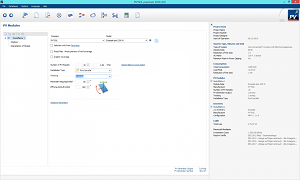
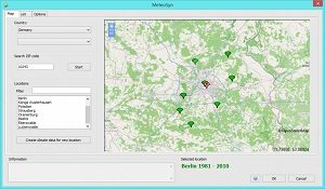
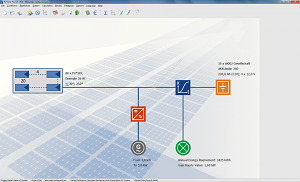

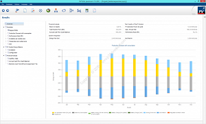
Leave a comment on this post or contact US to download PV*SOL Premium software
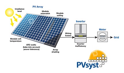
PVsyst is a PC software package for the study, sizing, simulation, and data analysis of complete PV systems. PVsyst is designed to be used by architects, engineers, and researchers. It is also a very useful educative tool. It includes a detailed contextual Help menu that explains the procedures and models that are used and offers a user-friendly approach with a guide to developing a project. PVsyst can import meteo data from many different sources, as well as personal data. PVsyst presents results in the form of a full report, specific graphs, and tables, and data can be exported for use in other software.
Management of the project: For a given project (a defined site and meteo), you can construct several variations for your system (“calculation versions”).
System design board: The system design is based on a quick and simple procedure:
Specialized tools are also provided for the evaluation of the wiring losses (and other losses like the module quality), the mismatch between modules, soiling, thermal behavior according to the mechanical mounting, system unavailability, etc.
Simulation and results report: The simulation calculates the distribution of energies throughout the year.
Main results:
1. The total energy production [MWh/y] is essential for the evaluation of the PV system’s profitability.
2. The Performance Ratio (PR [%]) describes the quality of the system itself.
3. The specific energy [kWh/kWp] is an indicator of production based on the available irradiation (location and orientation).
A powerful tool for a quick analysis of the system’s behavior, and potential improvements in the design.
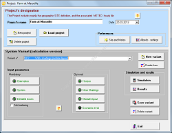
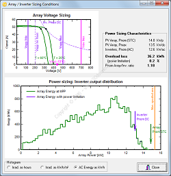
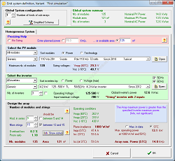

The RETScreen Clean Energy Management Software (usually shortened to RETScreen) is a software package developed by the Government of Canada. RETScreen is a Clean Energy Management Software system for energy efficiency, renewable energy, and cogeneration project feasibility analysis as well as ongoing energy performance analysis. RETScreen Expert, an advanced premium version of the software, is available in Viewer mode completely free of charge.

Providing Electric Power System Protection:
Increase efficiency and avoid costly mistakes by keeping yourself and your company’s employees trained on the protection of equipment.
Elec-Engg provides training materials on designing electrical protection schemes including the studies, programming, and integration of protective relays and their peripheral systems. Our training materials can be distributed in several ways.
Products: (https://elec-engg.com/category/products/)
Training Course: (https://elec-engg.com/category/training-course/)
Training course materials: (https://elec-engg.com/category/course/)
Our customers include large and small utilities, industrial plants, construction companies, project developers, system integrators, contractors, consultants, and electric transmission companies.
")
The training contains the INCOMING & COUPLING WIRING & TERMINATION DIAGRAM.

This article is planned to be a guideline for secondary protection practices basic calculations and setting procedures for DEMA MCR 310 Electronic Overcurrent Protection Relay. To form a basis for the calculations, a sample project /with the single line diagram on the left is created. When evaluating the project, it must be noted that;
The following pdf contains calculations, estimations, and graphics that show the fundamentals of protection for a power transformer by using the DEMA MCR 310 Electronic Overcurrent Protection Relay.

Functional description for TCS relay 7PA30
RELAY 7PA30*2-1AA00
The 7PA30 relay is designed to supervise the trip circuit for one trip coil of a circuit breaker. The trip circuit wiring is supervised from the positive supply to the negative supply whilst the circuit breaker is open or closed.
FEATURES
The supervision is done with a small current that flows through the supervision-circuit in series with the trip coil of the circuit breaker. The supervision current is always less than 1.4 mA. This makes the 7PA30 relay suitable for the supervision of circuit breakers with low power consumption down to 4.5 W. Therefore external current limiting resistors are not needed because these resistors are installed inside the 7PA30 TCS relay.
Both contacts and the LED are in series and therefore synchronized. In normal conditions, the 7PA30 cannot produce an unwanted trip due to the high impedance of its supervision circuit. Measures are taken to avoid a short circuit in the supervision module by integrating a component that melts in this case, avoiding an unwanted operation.
FUNCTIONAL DIAGRAM
The connection diagram below shows the 7PA30 with the complete trip circuit up to the trip coil of the circuit breaker.
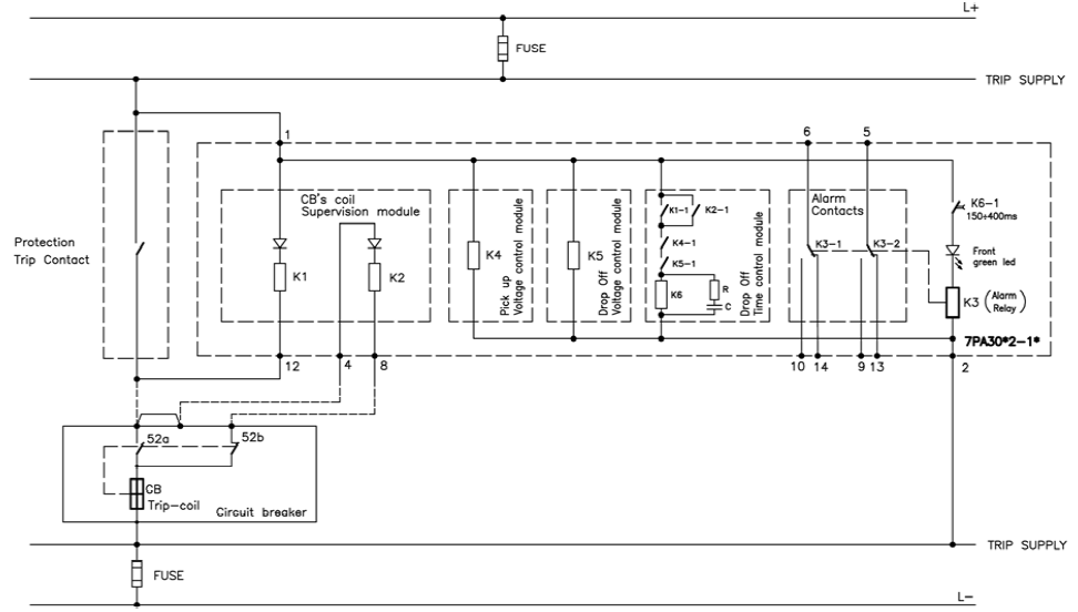
The contacts in the diagram above are shown without an auxiliary supply.
OPERATION
The LED is on and both contacts are in close position (terminal 5-9 and 6-10) whenever the trip circuit is healthy. The supervision is performed under the 4 possible conditions described in the following pages.
The supervision circuit is indicated (via K1, 52a, and the CB coil). K2 is not energized.
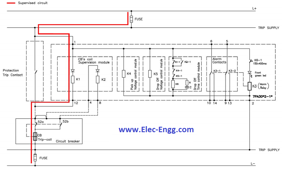
Different situations that can occur:
1.- If the trip supply falls below the assigned drop-off voltage, the drop-off voltage control module will detect it. Therefore K5 will drop-off and this will lead to the de-energization of K6 and K3 after 150ms. This will result in a trip circuit supervision alarm.
2.- In case of a broken connection in the supervision circuit, K1 will drop off and this will lead to the de-energization of K6 and K3 after 150ms. This will result in a trip circuit supervision alarm.
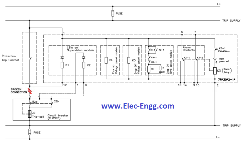
In this situation, the trip contact of the protection relay and the circuit breaker is closed. The supervision circuit is indicated (via 52a and the CB coil). K1 and K2 are not energized.
The operation time of the CB must be less than 150 ms, in order to avoid the drop-off of the relay. K6 is kept energized with an internal capacitor and therefore also the LED and K3 remain energized. This will avoid an unwanted alarm during operation.
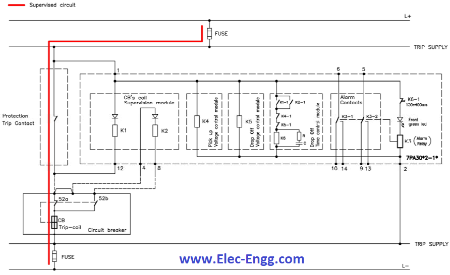
Trip contact is still closed in this situation although the CB has already opened. The supervision circuit is indicated (via K2, 52b, and the CB coil). K1 is not energized.
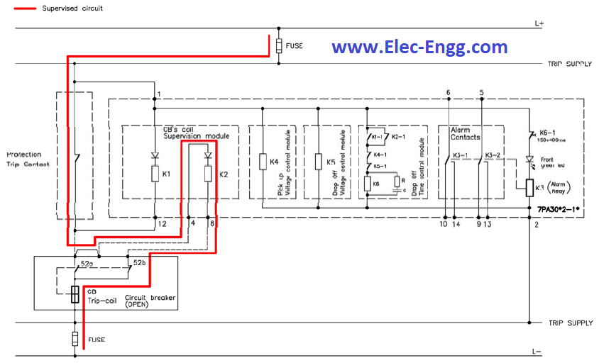
In this situation, the trip contact can remain closed, e.g. if the protection relay trip contact belongs to a lock-out relay.
In this case, the trip contact remains closed until the trip will be recognized and the lockout relay will be reset.
In this situation the trip contact of the protection relay and the circuit breaker is open. The supervision circuit is indicated. K1 and K2 are energized.
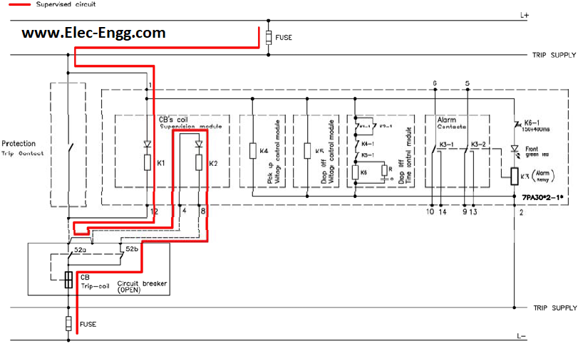
The following table resumes the four situations explained before:
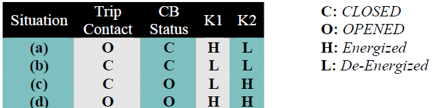
SELECTION AND ORDER NUMBER
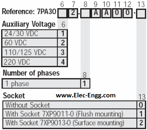
Download PSCAD file:
Contact us for more information

DIgSILENT has set standards and trends in power system modeling, analysis, and simulation for more than 25 years. The proven advantages of the PowerFactory software are its overall functional integration, its applicability to the modeling of generation-, transmission-, distribution- and industrial grids, and the analysis of these grids’ interactions. With PowerFactory Version 15, DIgSILENT presents a further step towards seamless integration of functionality and data management within a multi-user environment.
DIgSILENT PowerFactory is the most economical solution, as data handling, modeling capabilities, and overall functionality replace a set of other software systems, thereby minimizing project execution costs and training requirements. The all-in-one PowerFactory solution promotes a highly-optimized workflow. DIgSILENT PowerFactory is easy to use and caters to all standard power system analysis needs, including high-end applications in new technologies such as wind power and distributed generation and the handling of very large power systems. In addition to the stand-alone solution, the PowerFactory engine can be smoothly integrated into GIS, DMS, and EMS supporting open system standards.
Here are some key features of “DIgSILENT PowerFactory”:
Template networks in Digsilent to test the transient state package
Download


IEC 61850 System Configurator V5.40
The IEC 61850 System Configurator enables you to configure and set parameters for IEC 61850 stations (Edition 1 and Edition 2). This tool allows you to manage sub-networks, network communicators, and their IP addresses and to connect the information items of different communicators.
The IEC 61850 standard has been defined in cooperation with manufacturers and users to create a uniform, future-proof basis for the protection, communication, and control of substations.
The advantages of using this protocol are as follows:
The IEC 61850 System Configurator is an application whose functionality has been designed especially for the following operating systems:
Do you face the error ” Siemens IEC 61850 System Configurator has not been tested for this operating system”?
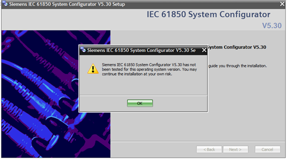
Do you face the error ” Siemens IEC 61850 System Configurator requires at least an earlier version of SYS-CON installed in the PC”?
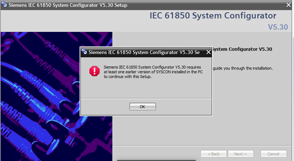

These spreadsheets below will make your endless calculations much easier!


Different technology has been used to implement protection functions that properly detect disturbances in the power systems and initiate the disconnection of the faulted components. Despite the developments of complex algorithms for implementing protection functions, microprocessor-based relays were marketed in the 1980s. Those relays performed essential functions, took advantage of the hybrid analog and digital techniques, and offered good economical solutions. The performance of these relays, however, was only adequate but their introduction did a lot of good to the highly conservative work of power system protection. Continuous advances in electronics, combined with extensive research conducted in microprocessor-based systems, led to a few applications in which a microprocessor relay performed multiple functions.
The following PDF is the report of the relaying practices subcommittee.
Download Understanding microprocessor-based technology applied to relaying
File Type: PDF
Size: 713 KB
")
The solutions from Siemens for energy automation offer a multitude of standardized configurations and functions for many typical tasks. These default settings allow the use of flexible products but at the same time is open for more challenging and customized applications. The acquisition of all kinds of data, computing, and automation functions, as well as versatile communication, can be very flexibly combined to create special solutions and to make integration into the existing system environment possible.
The process and visualization system SICAM SCC (SICAM Substation Control Center) is an important component of power automation solutions. Independent of the utilized substation, SICAM SCC can be used with both the power automation system.
SICAM PAS and also with the products of the SICAM RTU family. SICAM SCC can communicate directly with bay and protection devices that support the communications standard IEC 61850 and can be used for this as a cross-device HMI system. SICAM SCC is scalable for individual applications and supports efficient engineering for energy automation solutions of power utilities and industry.
Download SIEMENS Substation Automation System Part I (Practical)
Type: PDF
Size: 5 MB (139 pages)
Download SIEMENS Substation Automation System Part II (Practical)
There are two sections in “Mapping\PAS_FS1\PASCC\PASCC1_Interface\HMI “. One is “Information-Monitoring Direction” and the other one is “Information-Command Direction”.
In “Information-Command Direction” we should select “ION\EMA “and check the parameters which we want to use in our system.
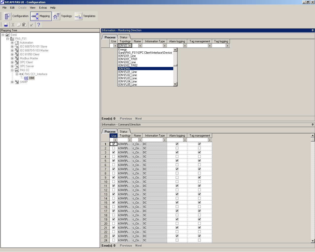
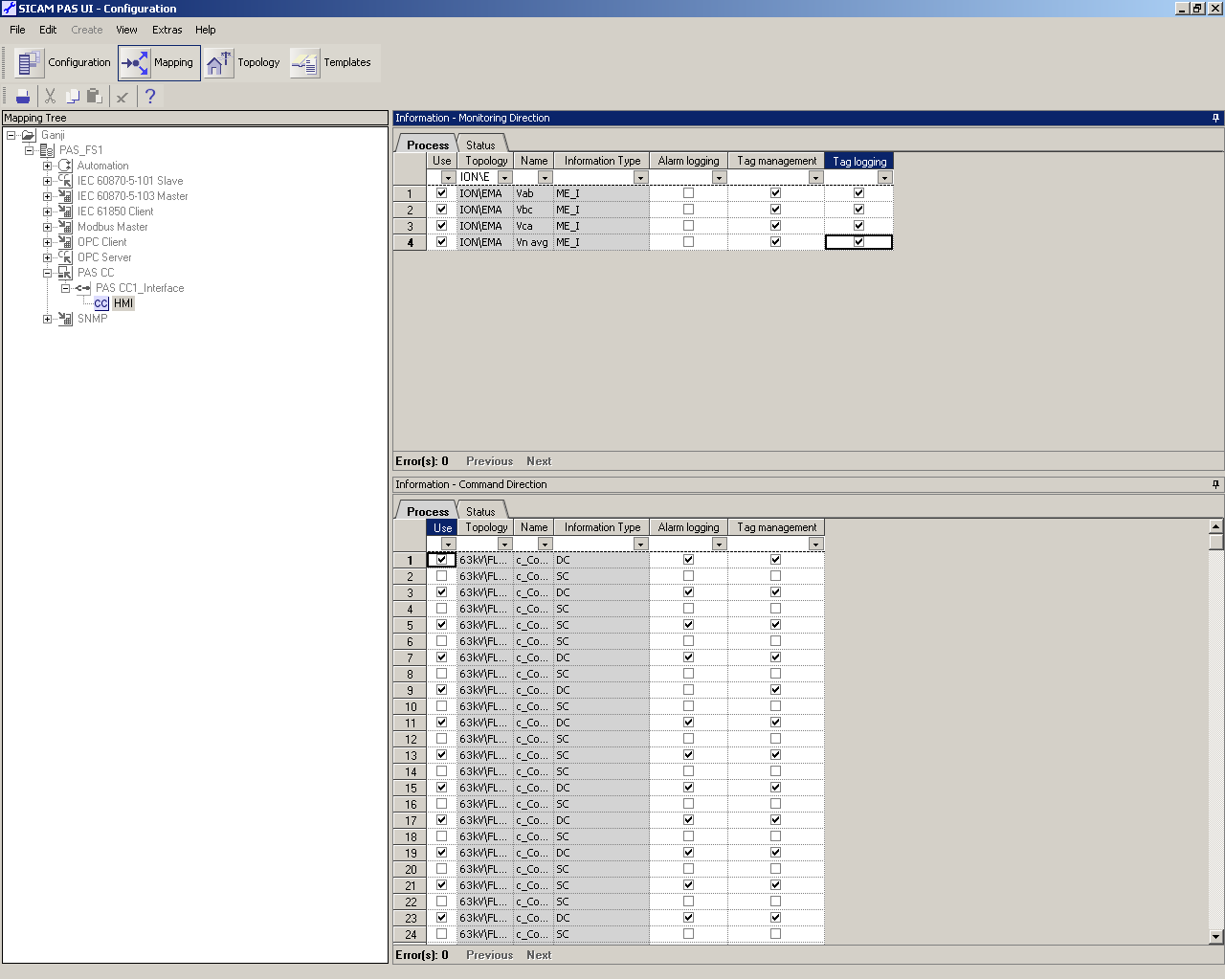
In “SICOM PAS CC \\ HMI\Graphic Designer “, we should create a window to show the parameters and double click on that.
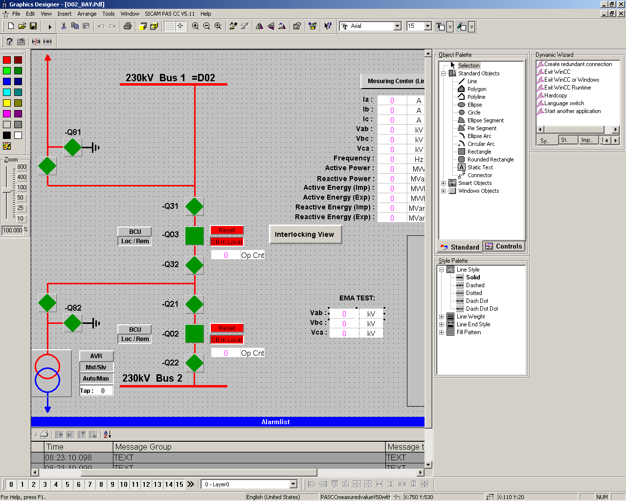
If the text is bold, it means that there are some changes to that. So click on the bold icon.
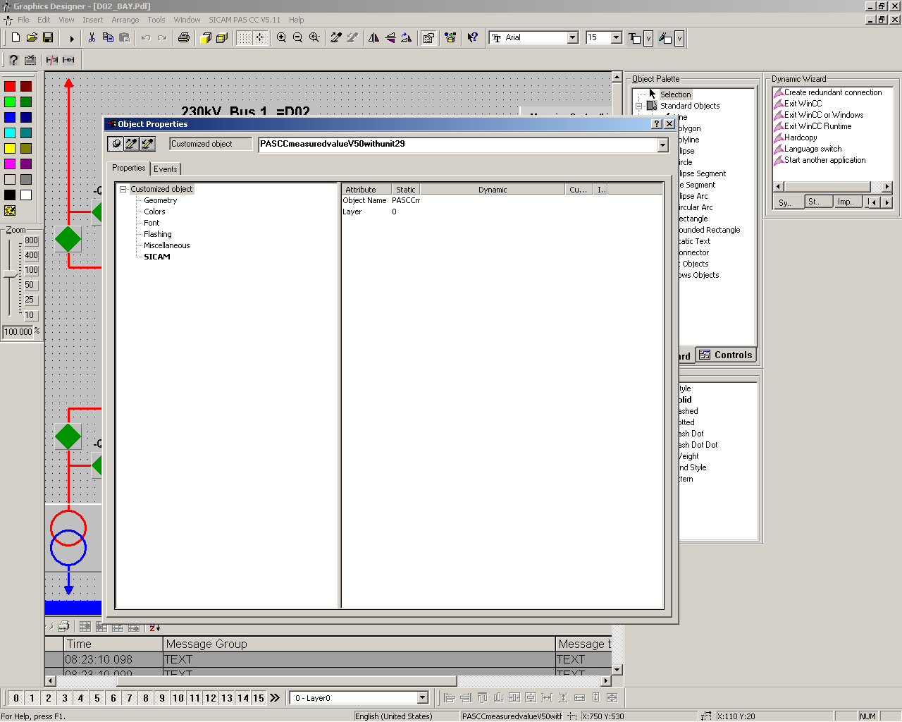
If the item has value, we can right-click on that and select the tag. Then from “HMI\ION_EMA”, we can select the values.
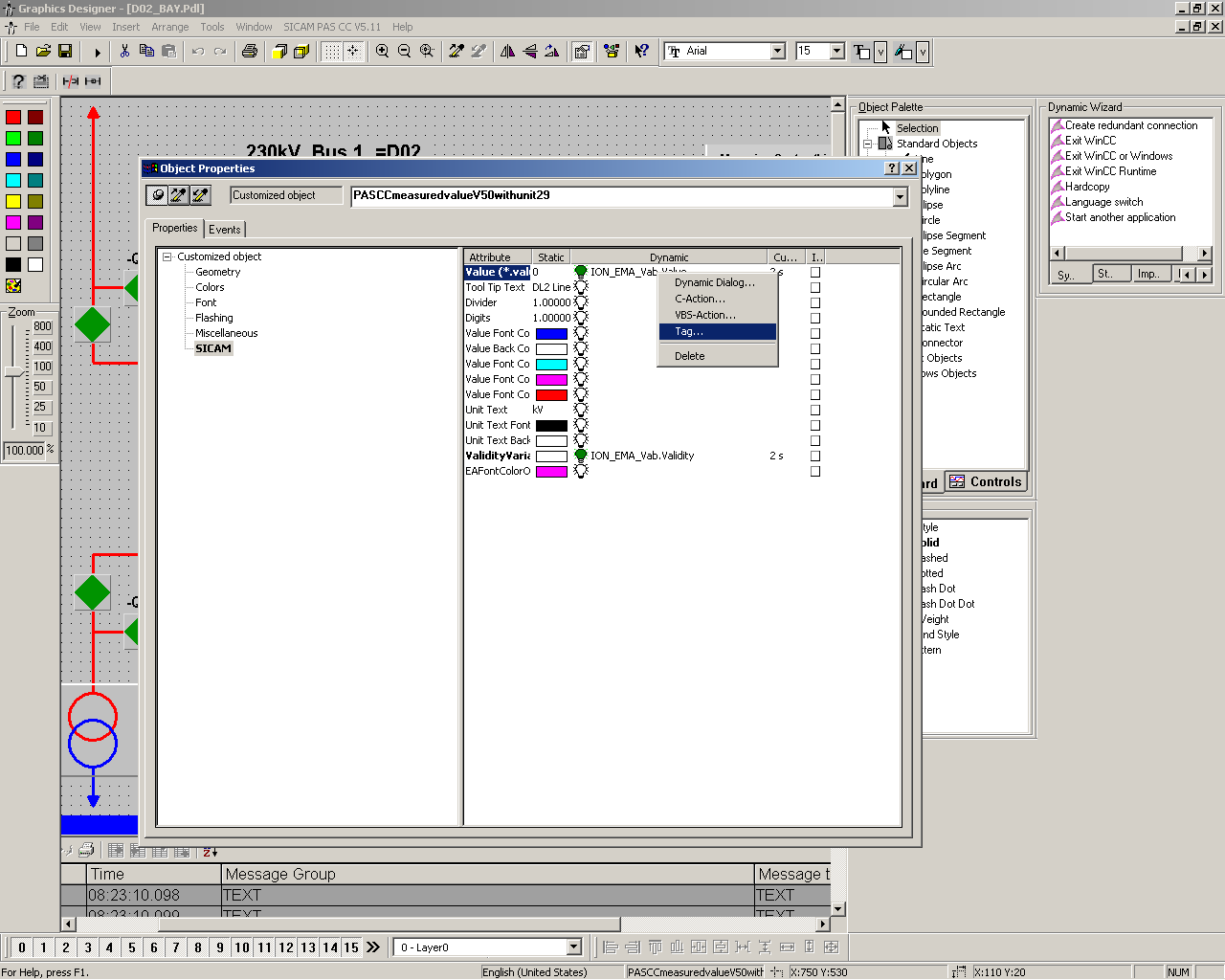
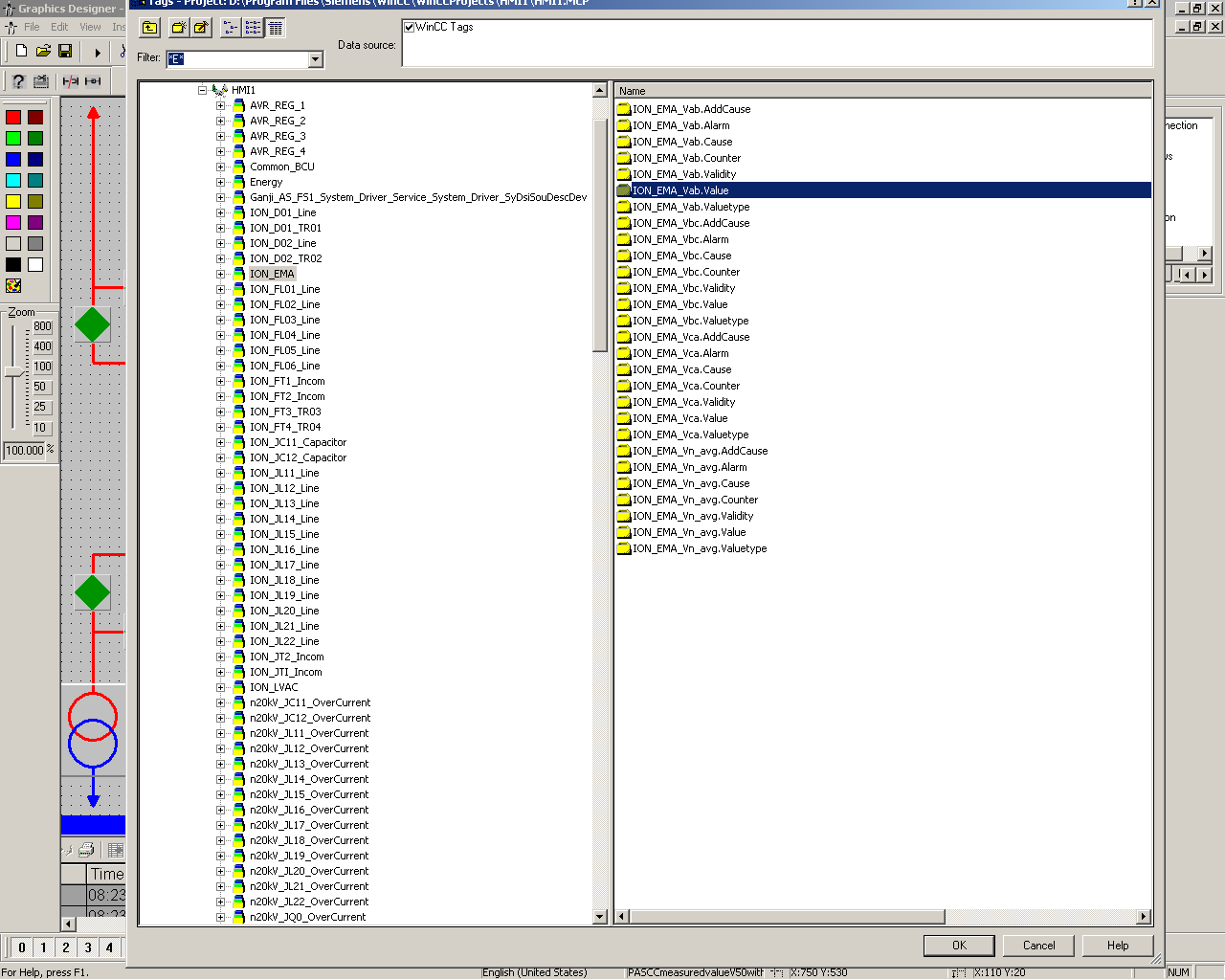
For the other manufacturer which supports IEC61850, they should provide relevant IEC61850 with the equipment. Here, for “REG-DA”, the IEC61850 file is “eberle35.icd”.
There are two options to add “REG-DA” in the Siemens Automaton System. One is with DIGSI and the other one is UI-Configuration.
We should import the IEC61850 file in our project.
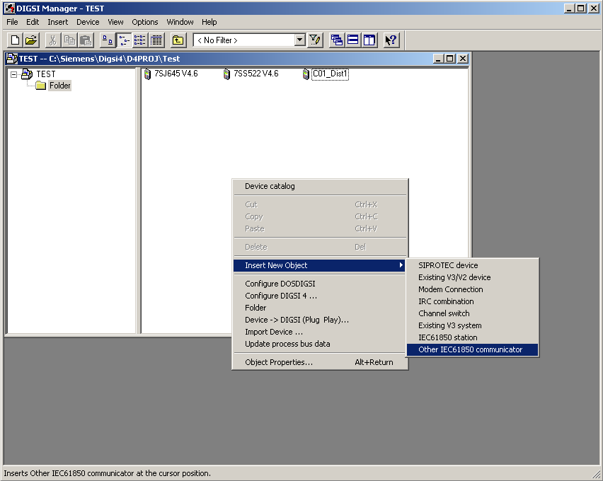
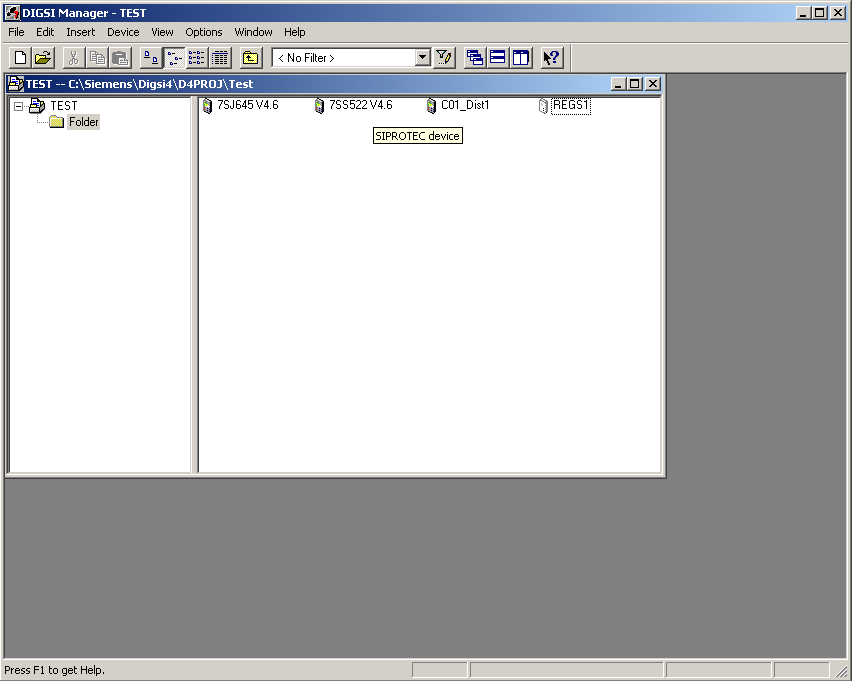
A file with the name of “*.icd” with creating automatically. If the number of “REG-DA” is more than one, we should change the “REGS1” to “REGS2”. To do this, we can open “eberle35.icd” with notepad and edit the file accordingly.

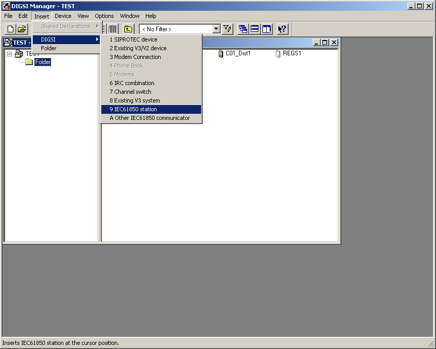
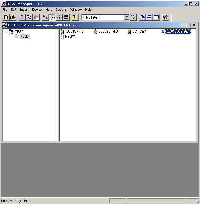
")
The PC operating program DIGSI 4 is the user interface to all Siemens protection devices, up to and including SIPROTEC 4 and
SIPROTEC Compact. It has a simple and intuitive user interface. Using DIGSI 4, the parameters for the SIPROTEC devices are set
and evaluated – it is a tailor-made program for industrial and energy supply systems.
SICAMPAS/PQS has been designed as a modular system with open communication interfaces. It thus meets the requirements of state-of-the-art substation control and protection systems and the power management systems required for industrial manufacturing plants. Functions for power quality evaluation complement its versatile fields of application. The system component SICAM PAS UI – Configuration is responsible for:
• Configuration and parameterization of your plant
• Exchange of configuration data
Example: Design a bay (one-and-half breaker) with distance and differential relays.
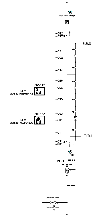
At first, we should create the relays with relative MLFB. Add a Control Device group in the configuration matrix.
For simplicity, add Control Device 2 and Control Device 3 for CutOff2 and CutOff 3 respectively.
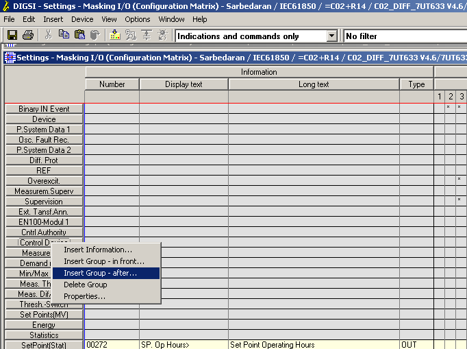
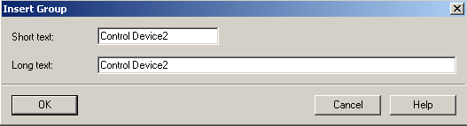

In Control Device2, select insert information for Q2. We want to control the Q2 form S=system and the position of Q2 with Binary Input (BI) 13 and 14.
If one of the inputs is true, it is open or closed. And if both of the BIs are true or false, it means an intermediate state.
From the list, select the Double point with zero states. Edit the name of the signal in Display text and Long text.
In the DP_I row (Dual Point indication), select BI 13 and 14 for Q2.
The source of the signal is System, so check the related box and set a name for that, here is Q2 and in switch type, select Disconnector.
Note: when we select the source for the signals, the Destination signals for BO with checked automatically. It means the signal will send to the system automatically.
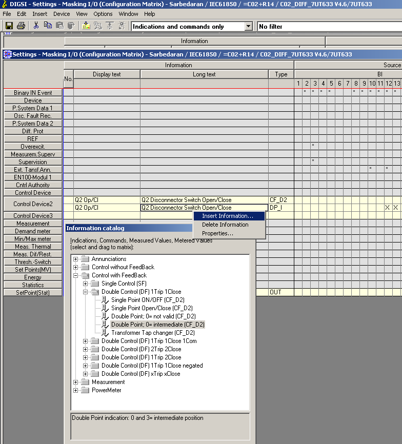
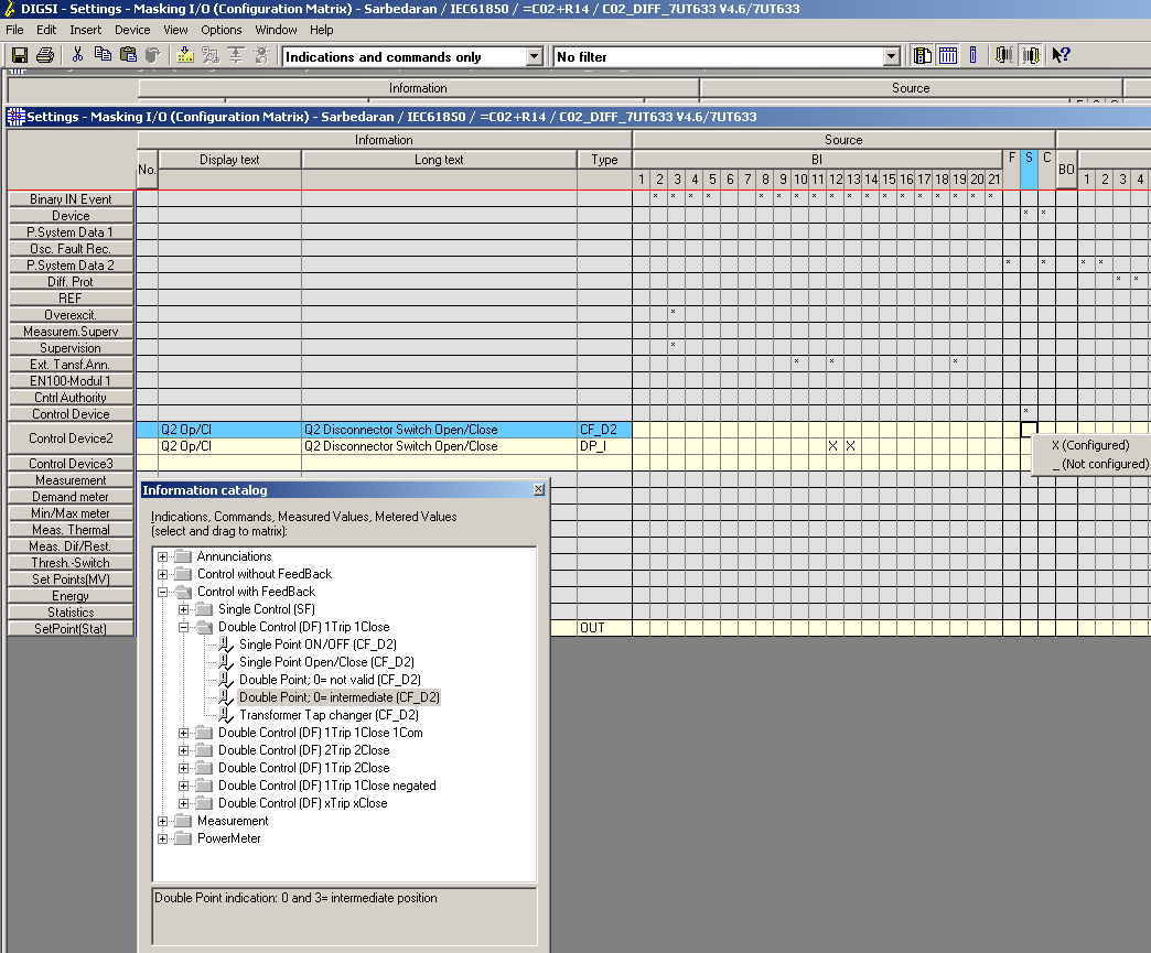
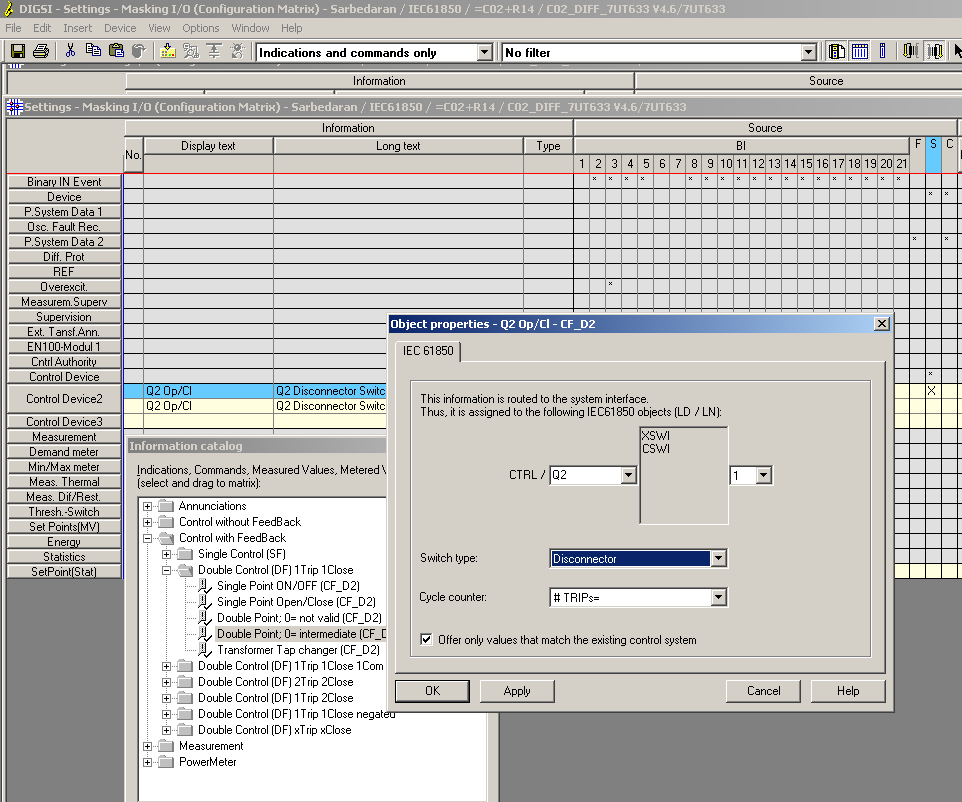
In Control Device2, select insert information for Q02. We want to control the Q02 form S=system and the position of Q02 with Binary Input (BI) 11 and 12.
If one of the inputs is true, it is open or closed. And if both of the BIs are true or false, it is intermediate.
From the list, select the Double point with zero states. Edit the name of the signal in Display text and Long text.
In the DP_I row (Dual Point indication), select BI 11 and 12 for Q02.
The source of the signal is System, so check the related box and set a name for that, here is Q2, and in switch type, select Circuit Breaker.
For a circuit breaker, we want to add the counter to count the number of open and closed positions. So form the signal list, select Value Indication (VI), and add it to the system.
For the source signal select Circuit Breaker for the switch type. And for the Cycle counter select the signal which is selected in Value Indication (VI).
Note: when we select the source for the signals, the Destination signals for BO with checked automatically. It means the signal will send to the system automatically.

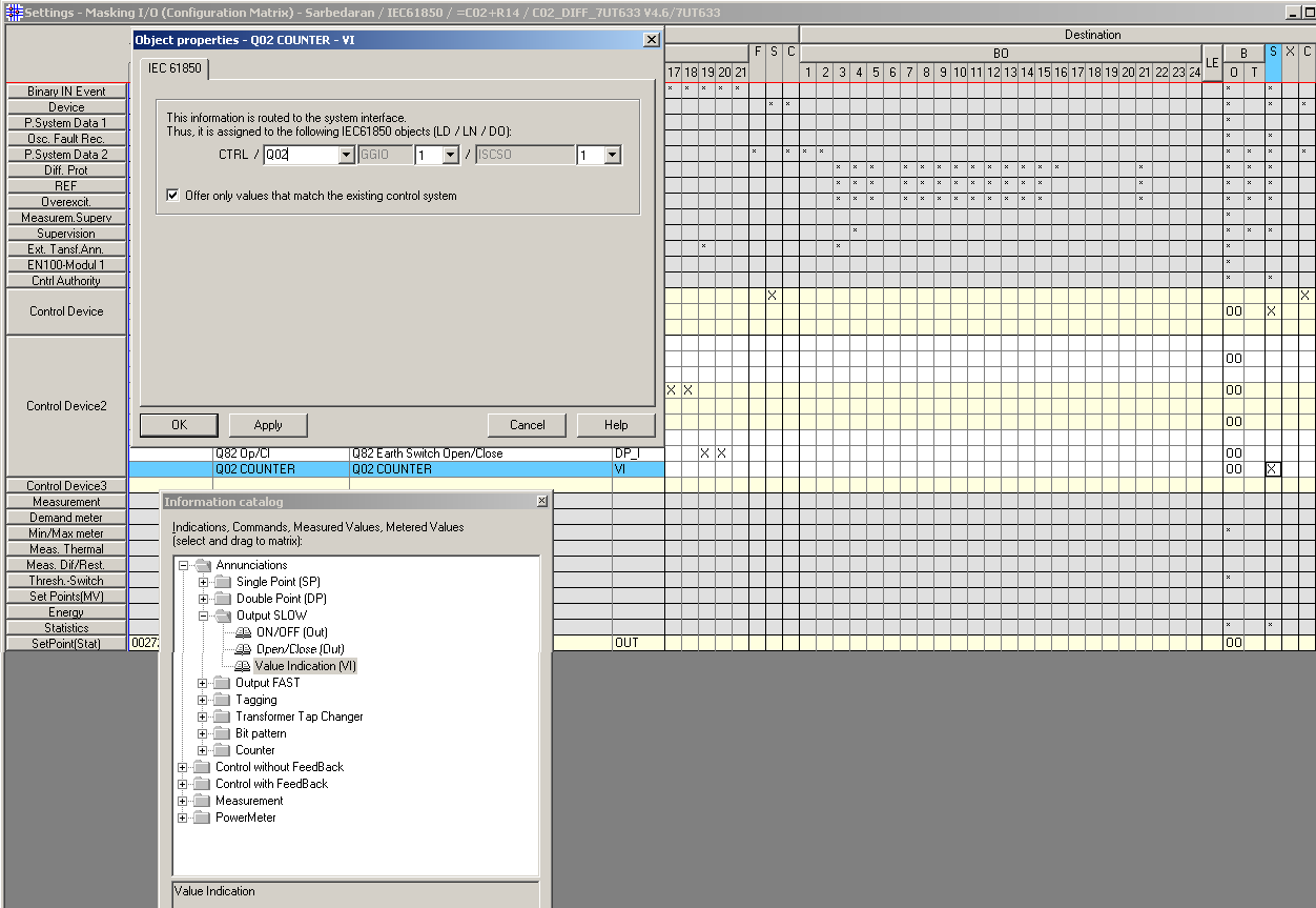
Within DIGSI, the difference between being “devices” and “variants” may not be obvious or significant, until the need for remote engineering access is considered. Each time a new device object is created within a DIGSI Project, a unique VD address is assigned as part of the setting file. Thus DIGSI ensures each “device” in a project has a unique VD address (“variants” don’t have a unique VD address and retain the VD address from when the file was created).
One of the purposes of the VD address is to provide an added level of security to remote engineering access. When connecting a DIGSI session via the rear remote service interface, the original setting file is needed in DIGSI to permit the connection to the relay. DIGSI compares the VD address of the setting file to the VD address in the remote device, to help ensure the correct “remote” relay is actually being connected to.
(VD address = Virtual Device address)
Object (setting file) VD address is reported and can be changed in Properties
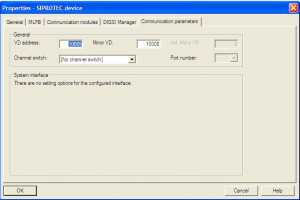
This document provides general information. You should follow your own network standard practices which may have specific procedures for the handling of device and variant files and assignment of VD addresses etc to support your specific commissioning/maintenance and remote engineering regimes. This is especially important where SICAM systems or IEC 61850 Protocols are used.
Note that the VD address is only ‘reported’ within the setting file “Interface Setting” section.
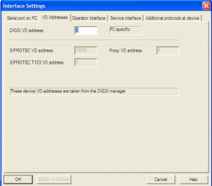
The VD address can be located and changed in the setting file via the Object Properties dialog. The VD address of the relay can be found via the LCD display using the appropriate front panel keys [Main Menu -> Settings (4) -> Setup/Extras (10) -> Device-ID (5)]
LOCAL & REMOTE CONNECTIONS
FRONT INTERFACE CONNECTIONS, PLUG & PLAY
When in front of a SIPROTEC 4 relay, the assumption is that you are an authorized person (by virtue of having access to the building), and that you have identified by panel labeling that you are connecting to the correct relay. Therefore, DIGSI permits connection to the relay front interface via “Plug & Play”.
What is Plug & Play?
Plug & Play is used to connect to a SIPROTEC device without the need to have a saved setting file (nor the need to know the relays VD address). Any setting file downloaded is of a SIPROTEC “variant” type.
Note that with Plug & Play, while you don’t need the original setting file, you must first have the matching parameter set installed on your PC. Parameter sets (DIGSI Device Drivers) are installed as part of the normal installation of DIGSI, during the “DIGSI Devices” installation phase, or as a subsequent download of a specific (updated) parameter set.
Plug & Play is the method recommended by HV Power for Technicians to capture copies of “as found” and “as left” setting files during any local work on a SIPROTEC 4 relay.
Other front panel connections:
Connection using a stored setting file by going “online” is also permitted (The VD address in the file is compared to that in the relay before allowing connection).
REAR SERVICE INTERFACE CONNECTIONS
Commonly the rear Service Interface on SIPROTEC relays are RS-485 ports (in systems other than those using IEC 61850 protocols). These rear Service Interfaces are normally daisy-chained, allowing one remote connection to be used to communicate to any SIPROTEC relay at the site.
To connect DIGSI via the rear service interface, you need the original setting file, as the connection is only permitted when the VD address of the file matches the intended relay. Note that if there are parameter value differences, such as old/new settings, provided the VD addresses match, the connection will occur, but with the choice to use either the relay data or the PC setting data given.
Plug & Play connection is not permitted over the rear Service Interface, as if remote, there would be no visual confirmation that you are connecting to the correct relay.
DEVICES & VARIANTS
With DIGSI setting files a SIPROTEC “device” is an object (setting file) with a unique VD address. A “variant” is an object (setting file) that is a copy of a “device” that has the same VD address as the original device.
Variants are identified in DIGSI Manager by the Var suffix in the name.
Variants are normally used where a temporary change to a setting file is required, such as creating an alternative setting (for the same relay) to be used when a line or transformer rating needs to be temporarily changed due to network maintenance, etc.
CREATING DEVICES & VARIANTS:
Insert new device: When inserting a new SIPROTEC device into a project (using the Device Catalogue), a “device” is created, and DIGSI automatically assigns a VD address that is unique to the project.
Plug & Play: Files created by Plug & Play will be of the variant type.
Copying Devices: Copy and Pasting a device in the DIGSI manager will create a new device (same settings, but with a different VD address). However, Copy and Pasting a variant will create another variant.
Create Variant: This command creates a variant file of an existing device or variant.
Import: When importing an object (setting file) into DIGSI, you are given the option to import as a variant or as a device.
Importing as a variant or device.
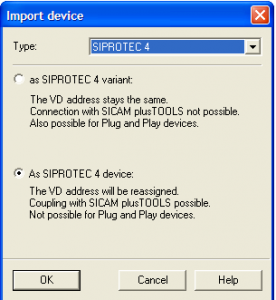
In general, if you are supplied a setting file to undertake work on a relay, such as for a setting change:
File >Reorganise
“Reorganising” a project (to clear free DIGSI memory) may cause the VD addresses within DIGSI to be changed.
Refer to the System Manual for notes on variants with regard to SICAM control center, IRC combinations, or process bus.
THE ROLE OF INITIALISING THE RELAY
A relay must be initialized at least once to allow communication with it. Normally relays are initialized by HV Power as part of our pre-delivery checks. Initialising is the process where a complete parameter set (a setting file) is loaded to the relay. This includes a VD address, thus providing a level of security for future remote engineering connections.
Warnings:
You will need to initialize the relay in the field only once during its first commissioning in order to load the designer’s intended setting file (with the specific intended VD address). Be aware of the above warnings and do not attempt to use Initialisation as a simple remedy for latter connection problems, without being aware of the implications.
By changing a VD address, depending upon your network’s remote engineering architecture, you may impact others’ ability to remotely connect to the relay, if they do not have access to the new VD address, or setting file.
A VD address in a relay can only be changed by the initialization/re-initialization process. It cannot be changed by the front panel keys; it cannot be changed by downloading a setting file with a modified VD address during plug & play connection, or via rear Service Interface. As relays cannot be initialized via the rear Service Interface, the VD address cannot be changed using the rear interface connection either.
VD & other addresses
With DIGSI and SIPROTEC 4 relays, there are actually several types of addresses including:
DIGSI4 VD address: This is the address given to the specific instance of DIGSI 4, The automatically assigned address is normally sufficient. The only time this would need to be changed is where simultaneous communication to both the front and rear service interfaces was required.
SIPROTEC-VD-addresses (VD, Mirror-VD, and redundant Mirror-VD): These are the VD addresses referred to in this document, controlled by the DIGSI Manager and transmitted to the SIPROTEC device to permit communication with the DIGSI Device Editor.
The Mirror-VD address and redundant Mirror-VD address are used for connection to control centers such as SICAM PAS.
SIPROTEC-T103 VD address: This address is used by IEC 103 communications to the System Interface (SCADA interface)
SICAM-Proxy VD Address: Used by SICAM Substation Management Systems for unique identification of SIPROTEC devices
IEC Link address: For front interface connections, this is 1. For rear Service Interface connections, if a star-coupler
is used, a unique IEC Link address has to be assigned to each SIPROTEC device (1 to 254)
For more information on VD addresses and communications, refer to Section 7 of the SIPROTEC System Description Manual
RS-485 Addressing & Star Couplers (IEC Link address)
The VD address should not be confused with the RS-485 address, which is different and additional. Where rear Service Interfaces are daisy-chained RS-485 circuits, each interface must be given a unique address. Figure 4 shows the “Address” field which should be set to a unique number (1 – 254) for each relay on a multi-drop connection to allow DIGSI to address a specific device. The same unique addressing requirement exists for connection of the Service Interface to Siemens star-coupler
RS-485 Daisy Chain Index
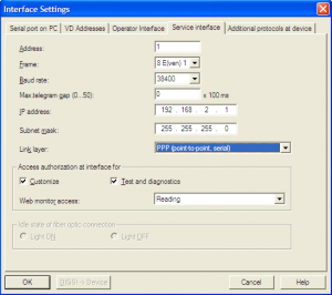
The Operator Interface Settings also has an “Address” setting similar to the Service Interface. Normally this is “1” as only one direct connection is made to this port at a time. However, it is possible to connect to multiple SIPROTEC Service Interfaces using Star-couplers and media converters, and thus this port can be given a unique address for DIGSI communications. In this case, all devices will “hear” the interrogation from DIGSI, but only the device with the matching DTE address (IEC Link address) will respond.
This provides a general overview of the process of setting/modifying DNP 3.0 maps in Siemens SIPROTEC 4 series Protection Relays, using DIGSI 4.
DNP 3.0 mapping information is part of the DIGSI “.dex” file information. It is not a separate file. The map is loaded/updated as part of the relay settings.
Mapping is achieved by routing items in the I/O matrix to/from the System Interface. (“System Interface” is Siemens term for the SCADA interface).
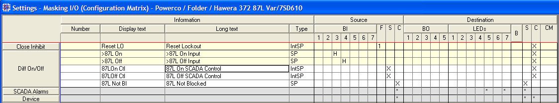
Note that if creating a setting file from a blank template, make sure the selected MLFB for the target relay includes a DNP protocol card, otherwise the points on the Matrix will not be able to be assigned to the DNP interface. [Right click to view the Properties on the setting file, prior to opening the file].
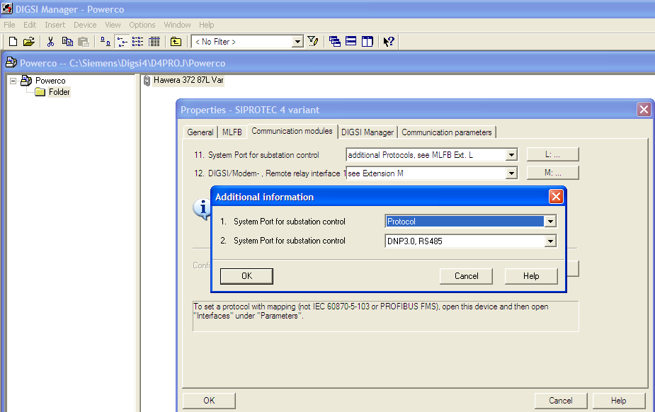
To set/change mapping, use the I/O Matrix
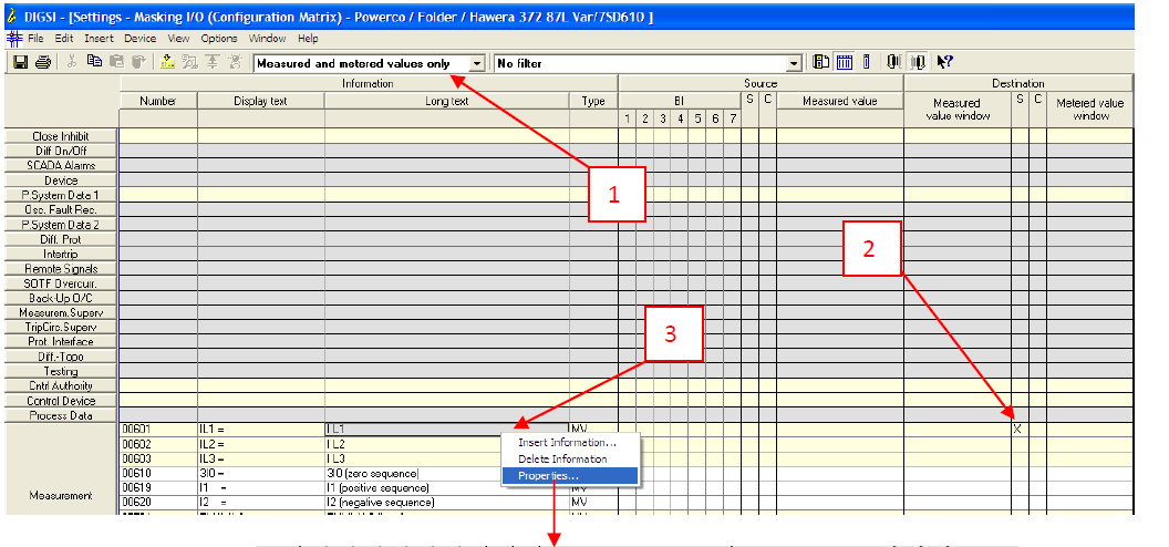
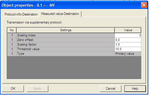
To print a copy of the DNP map
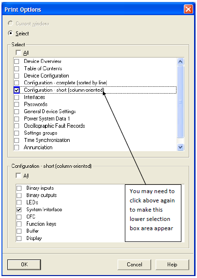
Notes/Warnings:
In the “Interfaces” object (below), the “Additional protocols at device” is used to set general SCADA parameters. Note that the below example shows “<see module-specific settings>” which indicates that the DNP map has been changed from the manufacturer’s standard. If you change this selection back to “DNP Map Standard…..”, all your DNP settings in the I/O matrix will be lost!
While the below appears to be a text report file, you can actually overwrite the settings to change the SCADA baud rate and other settings.
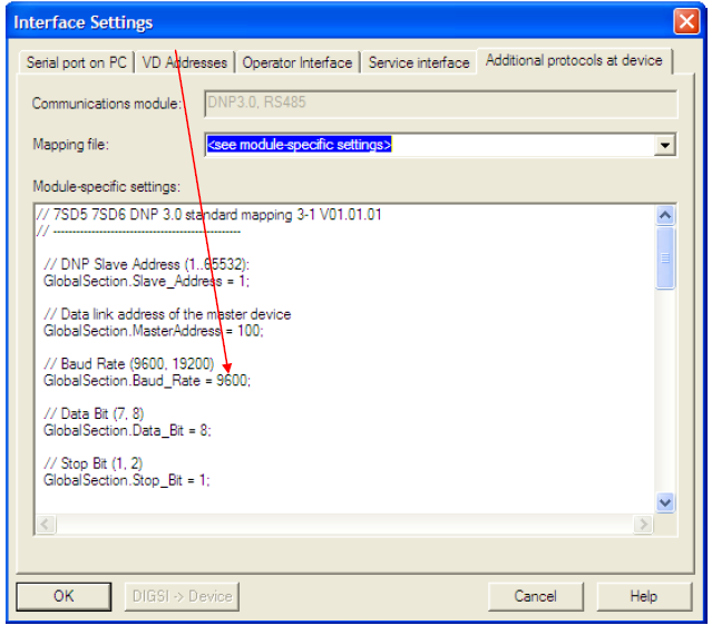
For further information:
All three manuals contain different information about DNP mapping.

Learning the fundamentals of relay testing, on your schedule. Learn how to efficiently test overcurrent, distance, and transformer differential relays with the OMICRON Test Universe. Our Training course provides you with relevant background information and takes your specific questions into account during the training. The material of the protective relay testing course is designed to help you to be a professional in this field.
Nothing beats hands-on learning from an engaging instructor who gives you the information you need and lets you practice in a safe environment.
we provide training courses at your site or online, contact us for reservations.

Numerical Distance Protection: Principles and Applications by Gerhard Ziegler
Distance protection provides the basis for network protection in transmission systems and meshed distribution systems. This book covers the fundamentals of distance protection and the special features of numerical technology. The emphasis is placed on the application of numerical distance relays in distribution and transmission systems. This book is aimed at students and engineers who wish to familiarise themselves with the subject of power system protection, as well as the experienced user, entering the area of numerical distance protection. Furthermore, it serves as a reference guide for solving application problems. For this fourth edition all contents, especially the descriptions of numerical protection devices and the very useful appendix have been revised and updated.

Electromagnetic Transient Analysis and Protective Relaying Techniques for Power Transformers
by Xiangning Lin, 2015
An advanced level examination of the latest developments in power transformer protection This book addresses the technical challenges of transformer malfunction analysis as well as protection. One of the current research directions is the malfunction mechanism analysis due to the nonlinearity of the transformer core and comprehensive countermeasures for improving the performance of transformer differential protection. Here, the authors summarize their research outcomes and present a set of recent research advances in electromagnetic transient analysis, and the application of power transformer protections, and present a more systematic investigation and review in this field. This research area is still progressing, especially with the fast development of Smart Grid. This book is an important addition to the literature and will enhance significant advancement in research. It is a good reference book for researchers in power transformer protection research and a good textbook for graduate and undergraduate students in electrical engineering. Chapter headings include: Transformer differential protection principle and existing problem analysis; Malfunction mechanism analysis due to the nonlinearity of transformer core; Novel analysis tools on operating characteristics of Transformer differential protection; Novel magnetizing inrush identification schemes; Comprehensive countermeasures on improving the performance of transformer differential protection advanced level examination of the latest developments in power transformer protection presents a new and systematic view of power transformer protection, enabling readers to design new models and consider fresher design approaches offers a set of approaches to optimize the power system from a microeconomic point of view.
Protective Relaying Theory and Applications
by Walter A. Elmore
Targeting the latest microprocessor technologies for more sophisticated applications in the field of power system short circuit detection, this revised and updated source imparts fundamental concepts and breakthrough science for the isolation of faulty equipment and minimization of damage in power system apparatus–clearly describing key procedures, devices, and elements crucial to the protection and control of power system function and stability.
Protective Relaying: Principles and Applications, Third Edition
by Domin, Thomas J.
Technological advances and structural changes within the electric utility industry mandate that protection engineers develop a solid understanding of the related new technologies as well as of power system operations and economics to function proficiently. Continuing in the bestselling tradition of the previous editions by the late J. Lewis Blackburn, Protective Relaying: Principles and Applications, Third Edition retains the fundamentals of protection relays and power system protection while incorporating new developments in the field. Thoroughly updated and revised, this third edition focuses on technological changes in the design of protective systems, the practical concerns of power system protection encountered by users, and the techniques for protecting typical facilities used in modern power systems. New to the Third EditionExpanded coverage of the requirements for generator intertie protection, generator protection, and generator excitation systems latest technologies in microprocessor applications, including digital-based devices and designs protection issues, such as capacitor bank protection, under frequency and Undervoltage load shedding, special protection schemes, DC tripping scheme designs, fault location, and event reports building on the excellence of the preceding editions, this book will continue to serve as a basic reference for newcomers to the area as well as for experienced engineers. By sharing his first-hand experience with protection practices, the author offers a valuable realistic insight into this field.
Protective Relaying: Principles and Applications
by J. Lewis Blackburn
Technological advances and structural changes within the electric utility industry mandate that protection engineers develop a solid understanding of the related new technologies as well as of power system operations and economics to function proficiently. Continuing in the bestselling tradition of the previous editions by the late J. Lewis Blackburn, Protective Relaying: Principles and Applications, Third Edition retains the fundamentals of protection relays and power system protection while incorporating new developments in the field. Thoroughly updated and revised, this third edition focuses on technological changes in the design of protective systems, the practical concerns of power system protection encountered by users, and the techniques for protecting typical facilities used in modern power systems. New to the Third Edition· Expanded coverage of the requirements for generator intertie protection, generator protection, and generator excitation systems· The latest technologies in microprocessor applications, including digital-based devices and designs· Protection issues, such as capacitor bank protection, under frequency and Undervoltage load shedding, special protection schemes, DC tripping scheme designs, fault location, and event reports Building on the excellence of the preceding editions, this book will continue to serve as a basic reference for newcomers to the area as well as for experienced engineers. By sharing his first-hand experience with protection practices, the author offers a valuable realistic insight into this field.
Protective relaying of power systems using mathematical morphology
by Q.H. Wu
The basic operating principles of the most common types of protection relays have not changed for more than half a century. However, the calculations used to measure power system fault signals continue to cause problems with relay performance. As a result, there is a need for developing the next generation of protection relays that are more accurate, more reliable, and faster than conventional relays. Protective Relaying of Power Systems Using Mathematical Morphology discusses the development of novel protective relaying algorithms using Mathematical Morphology (MM). MM is a nonlinear signal processing technique derived from set theory and geometry. It analyses signals in terms of shape by retrieving the features of the signals using a pre-defined structuring element. The book introduces the fundamental principles and brings together the applications of MM to develop new protective relaying algorithms for the protection of a variety of power system components (including transmission lines, buses, and power transformers), as well as for the distorted waveform detection and compensation which are required for the operation of many conventional relays. Protective Relaying of Power Systems Using Mathematical Morphology is an ideal source of information for researchers or postgraduates in the fields of power and engineering, as well as for power engineers.

Protective relaying for power generation systems
by Donald Reimert, CRC/Taylor & Francis
Protective relaying for power generation systems
by Donald Reimert
Protective Relaying Principles And Applications
by J Lewis Blackburn
Protective Relaying – Principles and Applns
by J. Blackburn
The Art and Science of Protective Relaying
by C. Russell Mason
IEEE Guide for the Application of Current Transformers Used for Protective Relaying Purposes
For more information Leave a comment here
Similar: eBooks – Protection Engineer- Pack I
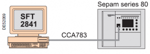
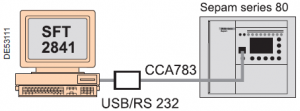
Keywords: sft2841 Download and Installation Guide with sft2841 serial number; sft2841 download; sft2841 download; sft2841 user manual; registration schneider electric; schneider product registration; sft2841 authorization code; sft2841 software download; sft2841 software serial number; SFT2841 password; SFT2841 authorization code; SFT2826 software download; sepam relay manual

Subscribe to us on LinkedIn
Subscribe on LinkedInSubscribe to us on WhatsApp
Be in touch with us on WhatsApp. Save +989129613659 as “Elec-Engg” in your contacts, and send a WhatsApp message as Subscribe.
Receive useful files and the latest news on Protection Relay, Protection Relay Testing, and IEC 61850 standards in your WhatsApp.
DIGSI4 training using examples. we will be taking you through all the key stages of working with DIGSI 4. Among other things, we will be showing you how to Create station topology, parameterize control monitor devices, Route information, Change display images, Configure logical functions, Task definition, Topology, Parameters, Routing, Logics, Display, Configuring busbar protection, Exchanging, and archiving data, Analyzing faults with SIGRA 4, Working online, Modem Connection, Direct Connections, Ethernet and IEC 61850
Training on DIGSI 4 and DIGSI 5 Training, contact us
Rs 2500 Click here to pay on
leave a comment on this post or Contact us for details

DIgSILENT Power Factory software is one of the most powerful network analysis software that is used in all the areas of generation, transmission, and distribution. DIgSILENT stands for DIgital SImuLation and Electrical NeTwork calculation program.
The purpose of this training is to acquaint engineers with the process of analyzing power systems to carry out research, industrial and other projects. Using this software, almost any power network can be modeled and calculations such as load flow, short circuit, transient analysis, optimal capacitor placement, cable size optimization, etc. can be provided in the form of various functions. In addition, other features such as programming in DPL language and defining DSL models provide the flexibility for the user to perform the desired analysis on the power system and the equipment that is not available in the software library.
DIGSILENT Training Course Contents – Basic
General introduction and software capabilities
Equipment modeling
Load-flow study
Single contingency (N-1) study
Short-circuit study
Transient stability study
DIGSILENT Training Course Contents – Advanced
Voltage stability study and capacitor placement
Power quality and harmonics
Load modeling
Modal analysis
Protection study
Reliability study
DPL Introducing

Main Training:
new videos will be added soon!
Supplementary files:
This document provides the DIgSILENT PowerFactory Relay library of various manufacturers.
RACID.dz
RADS-B.dz
RADS-C.dz
RAKZB.dz
RAZFE.dz
RAZOA.dz
RED 670.dz
REF 542+.dz
REF 550.dz
REF 601.dz
REF610.dz
REF615.dz
REG 216.dz
REG 670.dz
REJ 521.dz
REJ 523.dz
REJ 525.dz
REJ 527.dz
REJ 603.dz
REL 100.dz
REL 300.dz
REL 301.dz
REL 511.dz
REL 512.dz
REL 521.dz
REL 531.dz
REL 561.dz
REL 670.dz
REM 543.dz
REM 610.dz
RET 670.dz
RR3M.dz
RxAs52k.dz
RXIDF.dz
RXIDG.dz
RXIDK 2H.dz
RXIDK 4.dz
RXIG.dz
RXPDK.dz
RYDSA.dz
SACE ISOMAX S1-S8.dz
SACE PR121.dz
SACE PR122.dz
SACE PR123.dz
SACE PR221_PR211_PR212.dz
SACE PR231.dz
SACE PR33x.dz
SACE TMAX T1-T7.dz
SD14.dz
SD34.dz
SEL 251.dz
SEL 267.dz
SEL 279.dz
SEL 300G.dz
SEL 311A.dz
SEL 311B.dz
SEL 311C.dz
SEL 311L.dz
SEL 321.dz
SEL 351.dz
SEL 351R.dz
SEL 387.dz
SEL 411L.dz
SEL 421.dz
SEL 451.dz
SEL 487E.dz
SEL 501.dz
SEL 551.dz
SEL 587.dz
SEL 700G.dz
SEL 751.dz
SEPAM 10.dz
SEPAM x20.dz
SEPAM x4x.dz
SEPAM x8x.dz
Siemens 3WN1_3WS.dz
Siemens 3WN6.dz
Solkor M.dz
Solkor N.dz
Solkor R-Rf.dz
SPAD 346.dz
SPAF 140C.dz
SPAJ 110C.dz
SPAJ 111C.dz
SPAJ 115C.dz
SPAJ 131C.dz
SPAJ 135C.dz
SPAJ 140C.dz
SPAJ 141C.dz
SPAJ 142C.dz
SPAJ 144C.dz
SPAJ 160C.dz
SPAJ 32x.dz
SPAM 150C.dz
SPRECON E-P DS.dz
SPRECON-E DD.dz
SPRECON-E-P DSR.dz
TLS 1000.dz
UR D60.dz
UR F60.dz
UR G30.dz
UR G60.dz
UR L90.dz
VAMP 130.dz
VAMP 135.dz
VAMP 140.dz
VAMP 150.dz
VAMP 210.dz
VAMP 230.dz
VAMP 245.dz
VAMP 255.dz
VAMP 257.dz
VAMP 265.dz
VAMP 40.dz
VDG14.dz
VIP 30 – 35.dz
VIP 300.dz
Download

Traditional protective relay books are written by engineers as a resource for engineers to use when modeling the electrical system or creating relay settings, and they often have very little practical use for the test technician in the field. The Relay Testing Handbook is a practical resource written by a relay tester for relay testers; it is a comprehensive series of practical instructional manuals that provide the knowledge necessary to test most modern protective relays. The complete handbook combines basic electrical fundamentals, detailed descriptions of protective elements, and generic test plans with examples of real-world applications, enabling you to confidently handle nearly any relay testing situation. Practical examples include a wide variety of relay manufacturers and models to demonstrate that you can apply the same basic fundamentals to most relay testing scenarios.
This Package contains five handbooks:

power system protection enclosure:
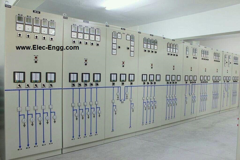
power system protection enclosure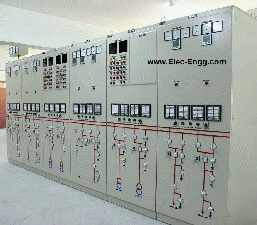
This picture shows a power transformer in an HV substation
Line Protection with GE relay
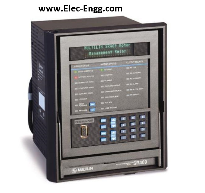
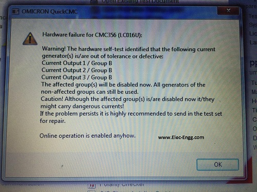
Hardware failure for CMC 356: Warning! The hardware self-test identified that the following current generators are out of tolerance or defective:
Current output / Group
The affected group will be disabled now. All generators of the non-affected groups can still be used.
Caution! Although the affected groups are disabled now they might carry dangerous currents! might carry dangerous currents!
If the problem persists it is highly recommended to send in the test set for repair. Online operation is enabled anyhow.
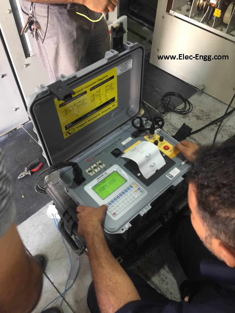
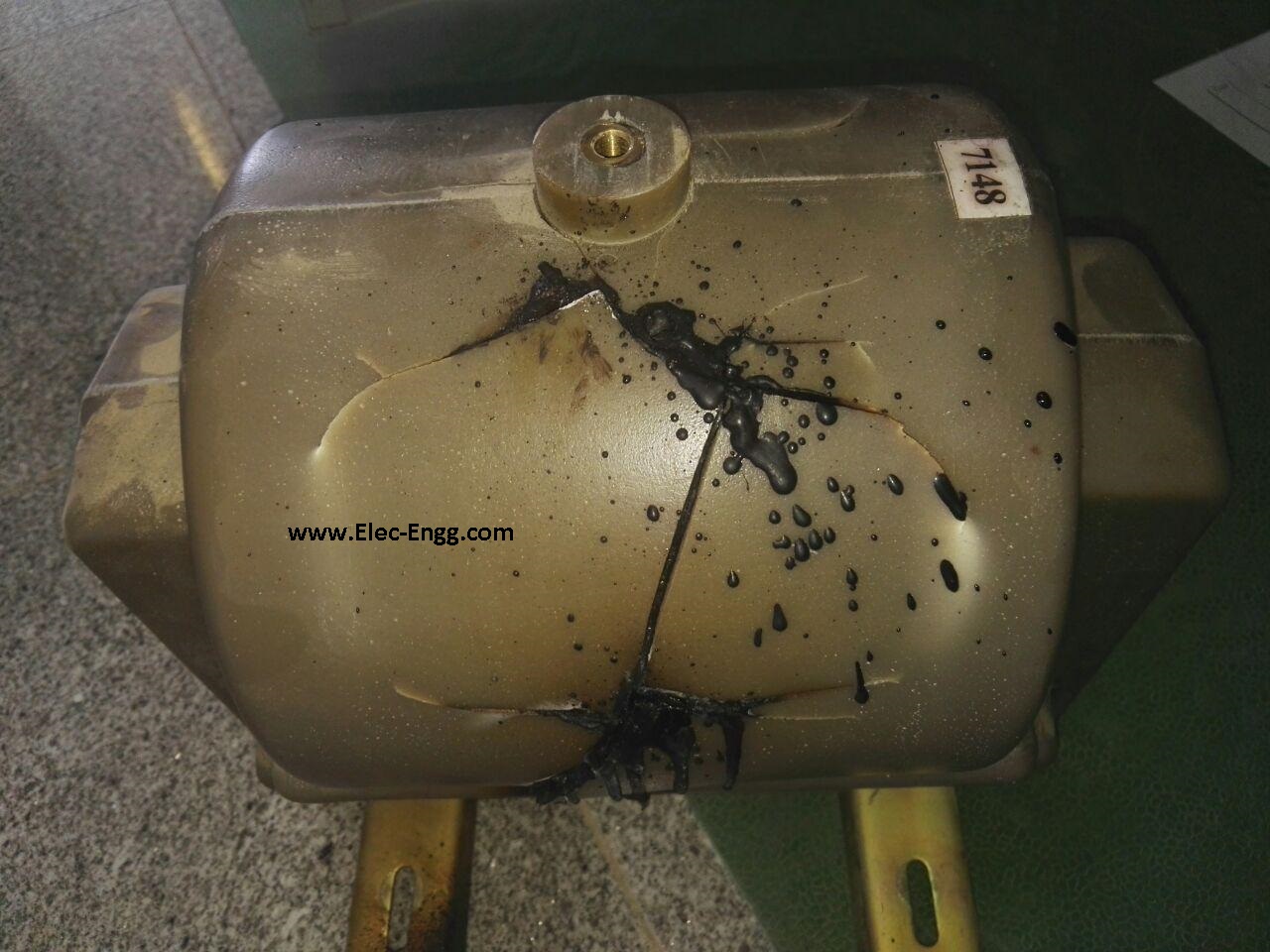
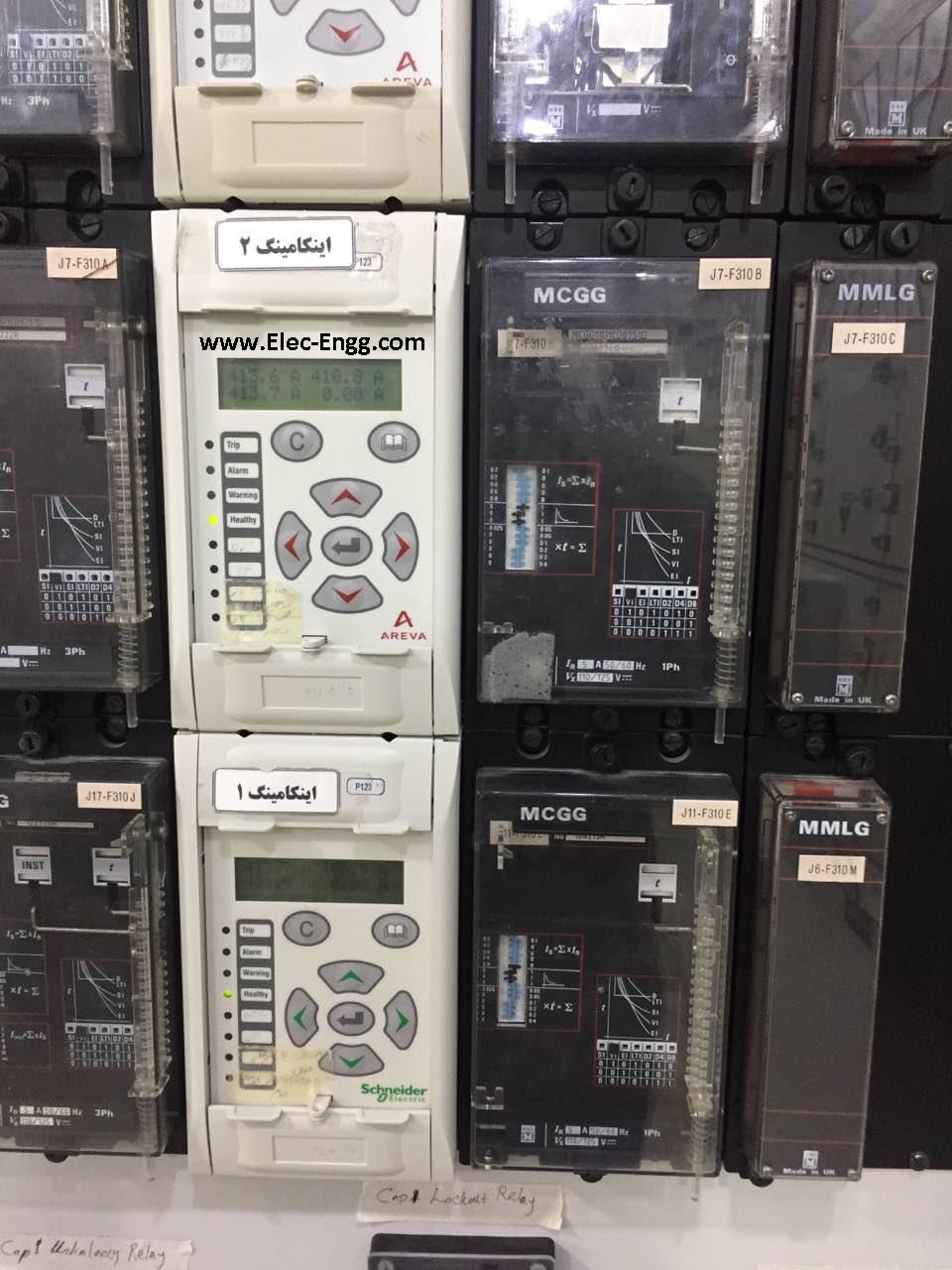
Areva or Schneider Electric relays in a cubicle
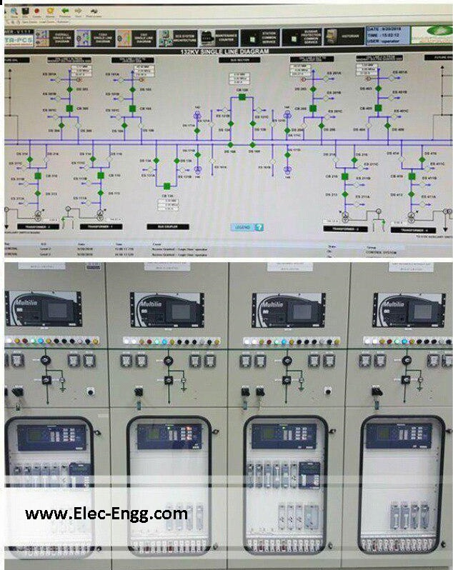
Substation Automation system and SEL relays in a substation
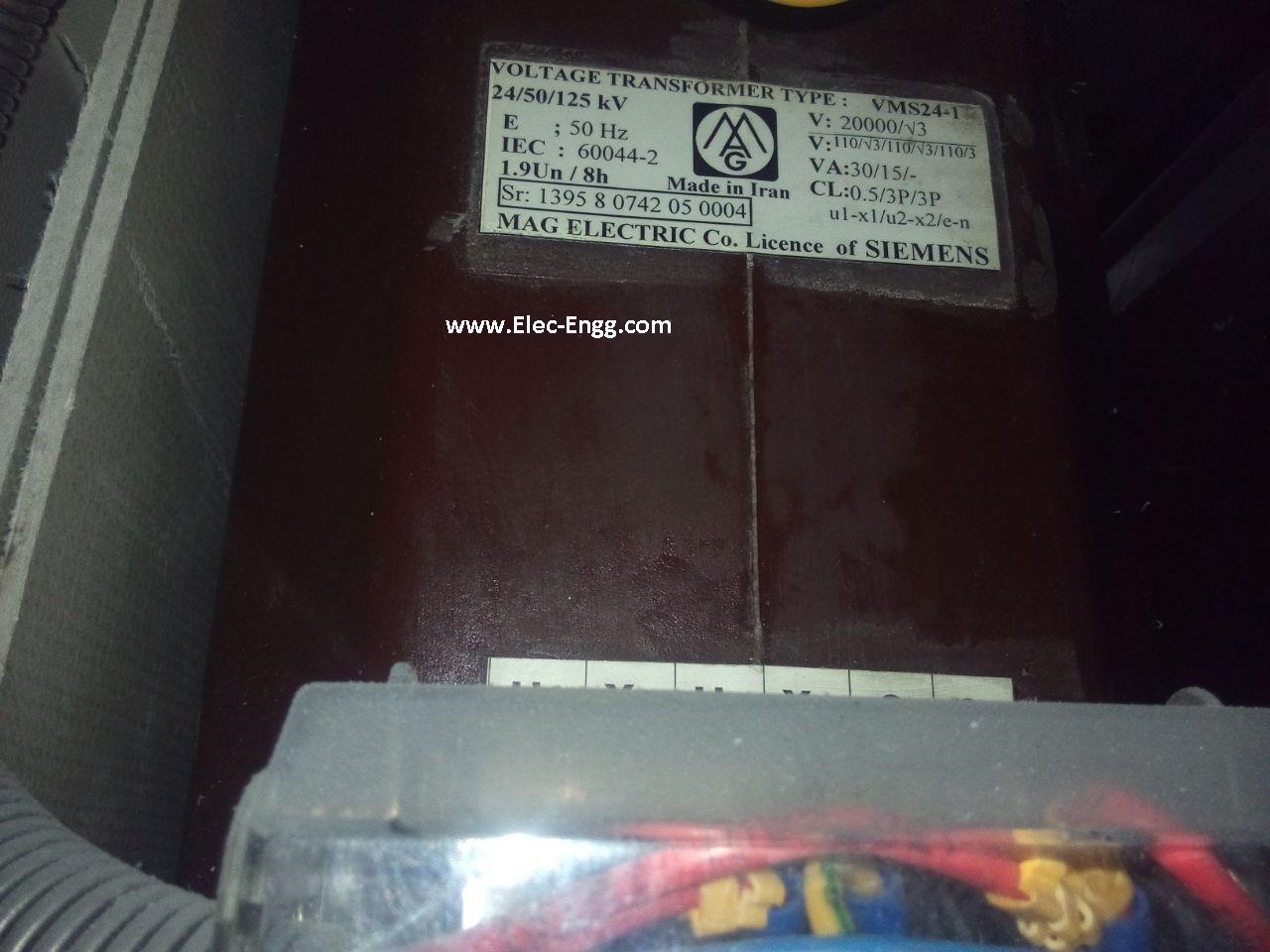
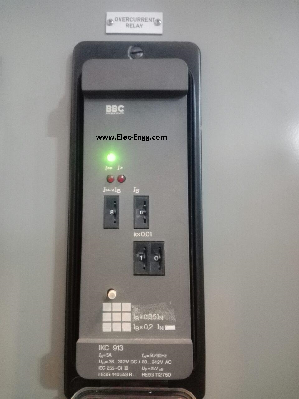
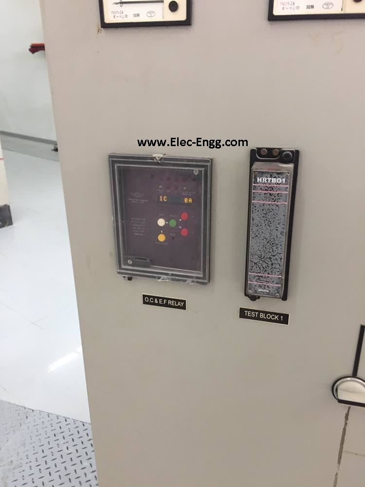
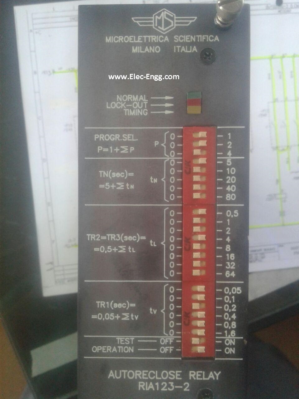
Microelecttrica sciendtifica Milano Italia
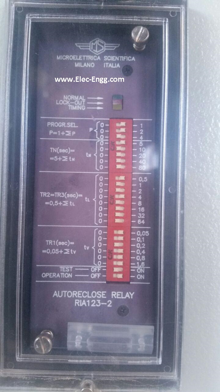
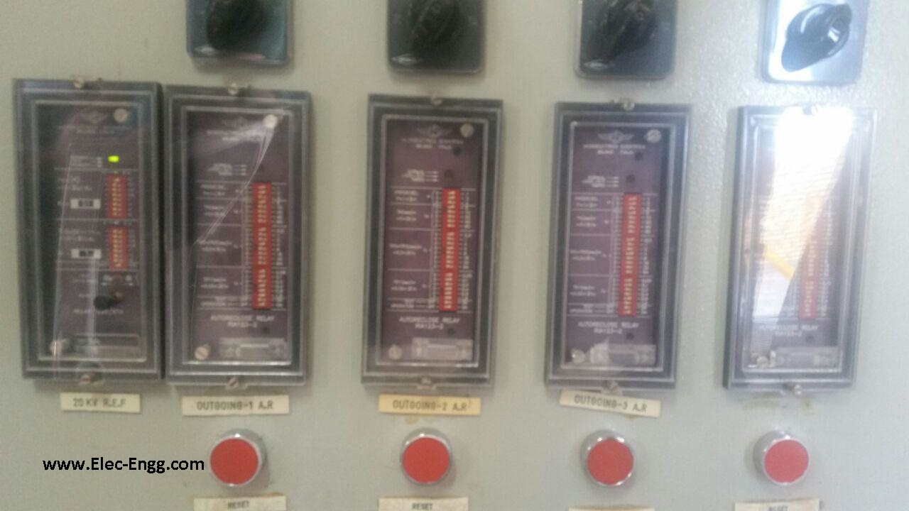
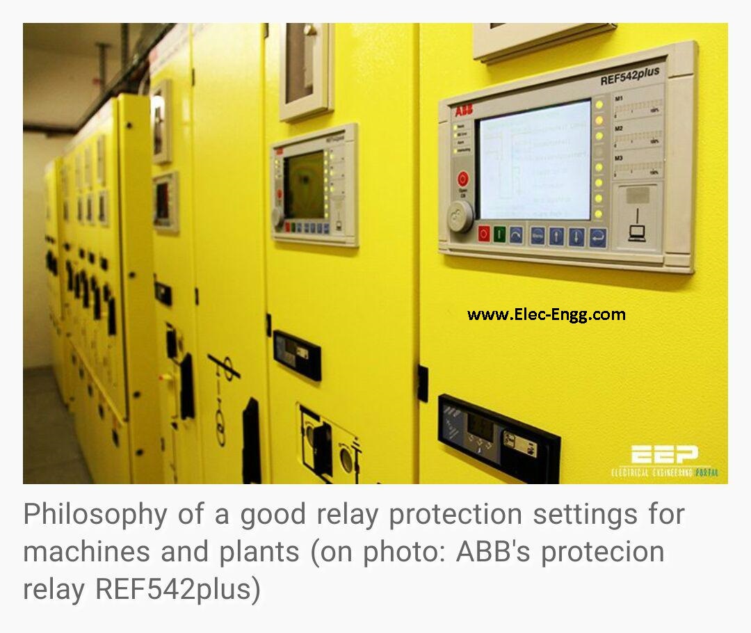
Philosophy of good relay protection settings for machines and plants – on photo: ABB Protection relay REF 542 Plus
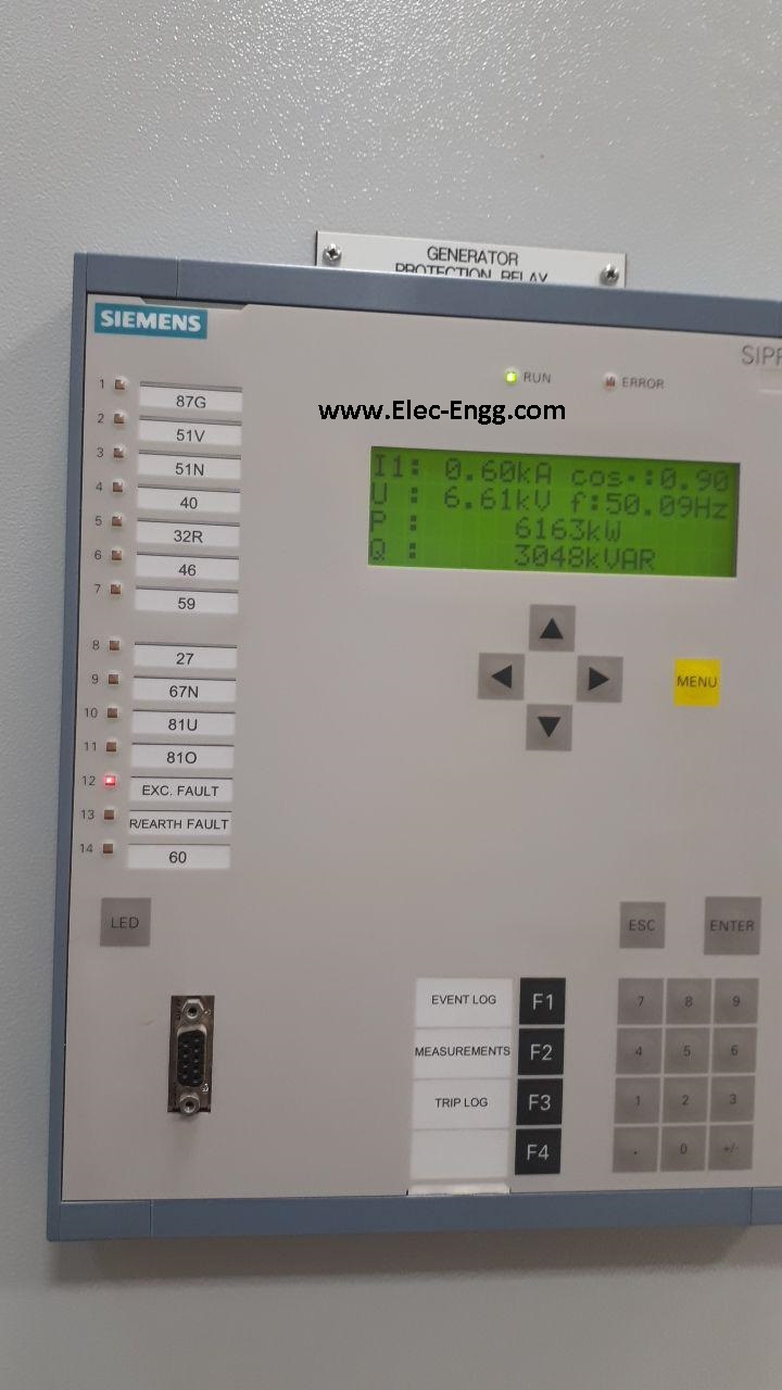
SIEMENS SIPROTEC 4 Relay
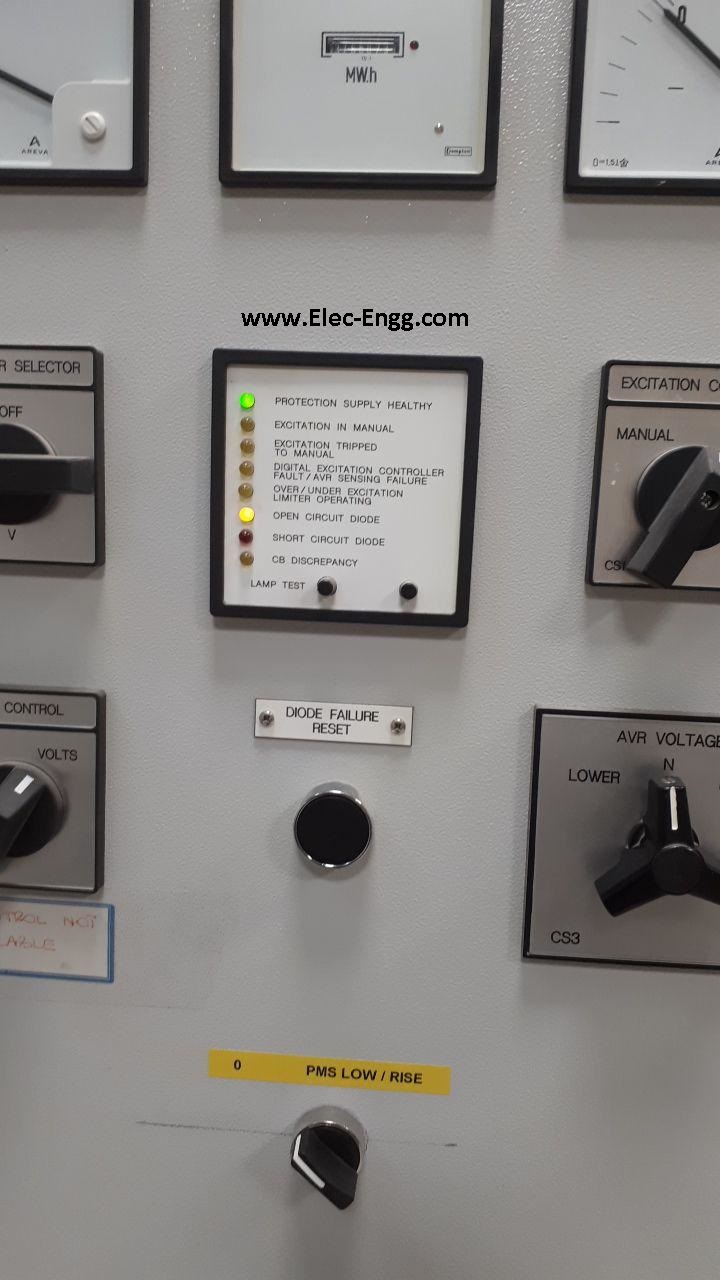
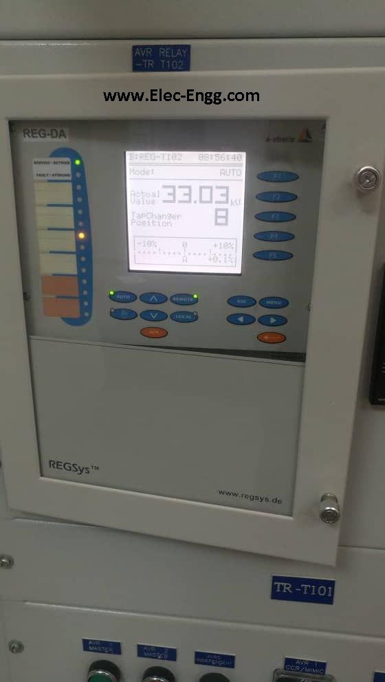
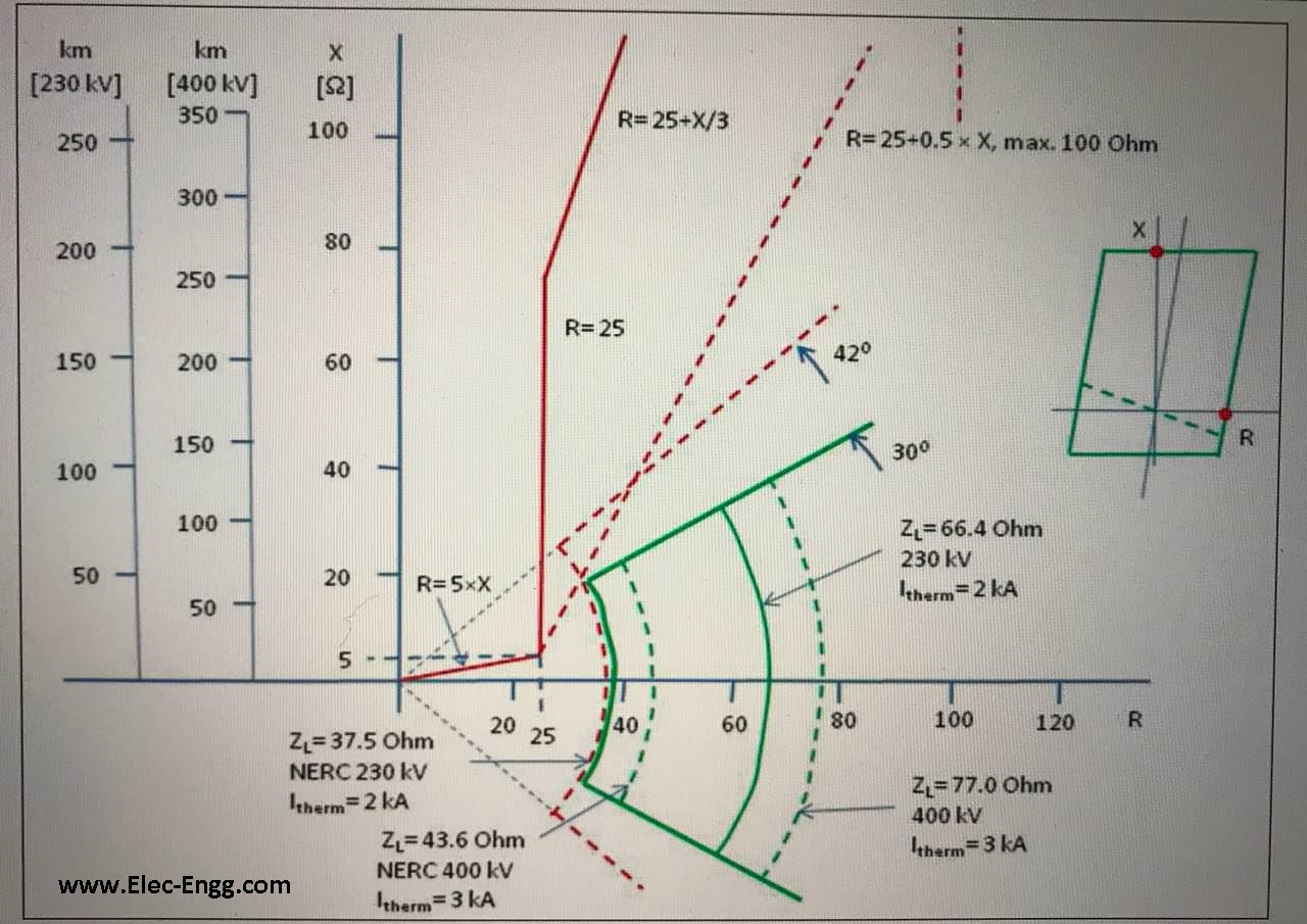
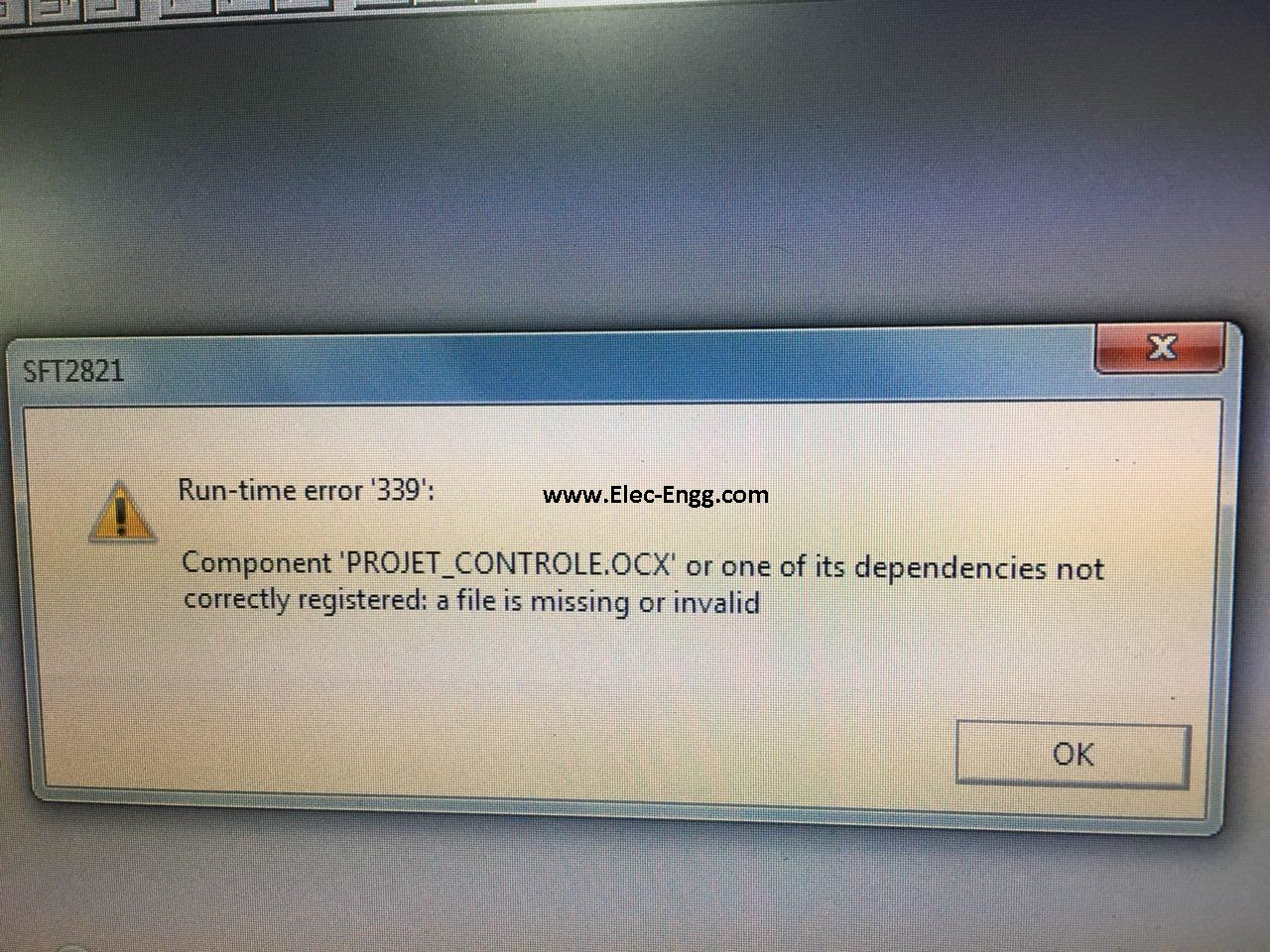
SIEMENS SIPROTEC 5 Relay
Online SIEMENS SIPROTEC 5 relay
SIGRA 4 needs a serial number to activate; you can register your DIGSIwith a valid serial number along with SIGRA 4 software
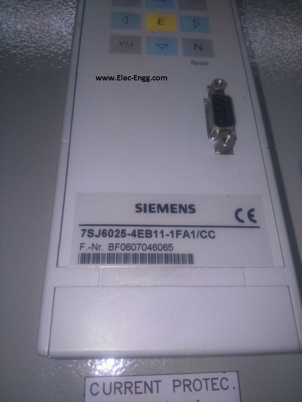
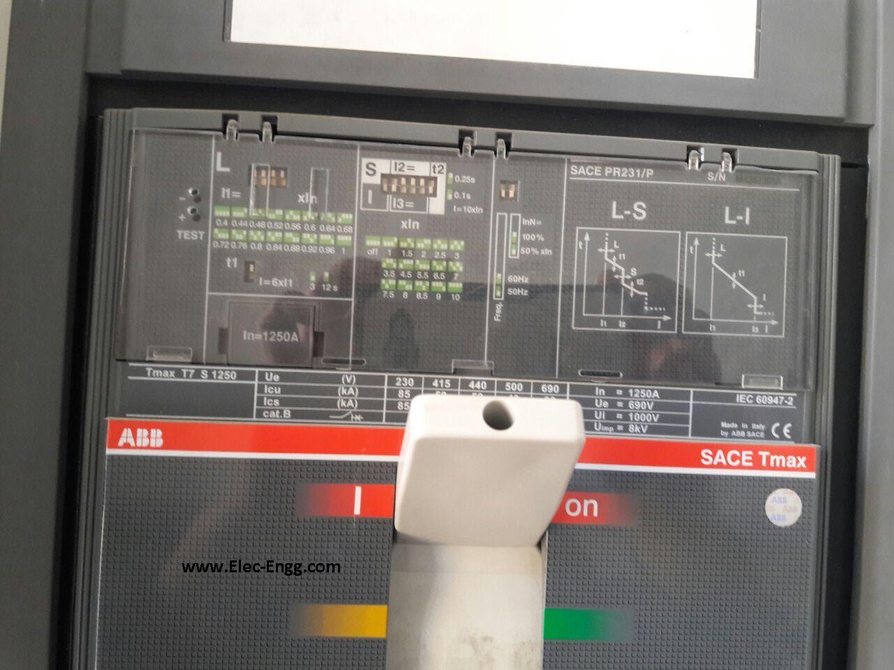
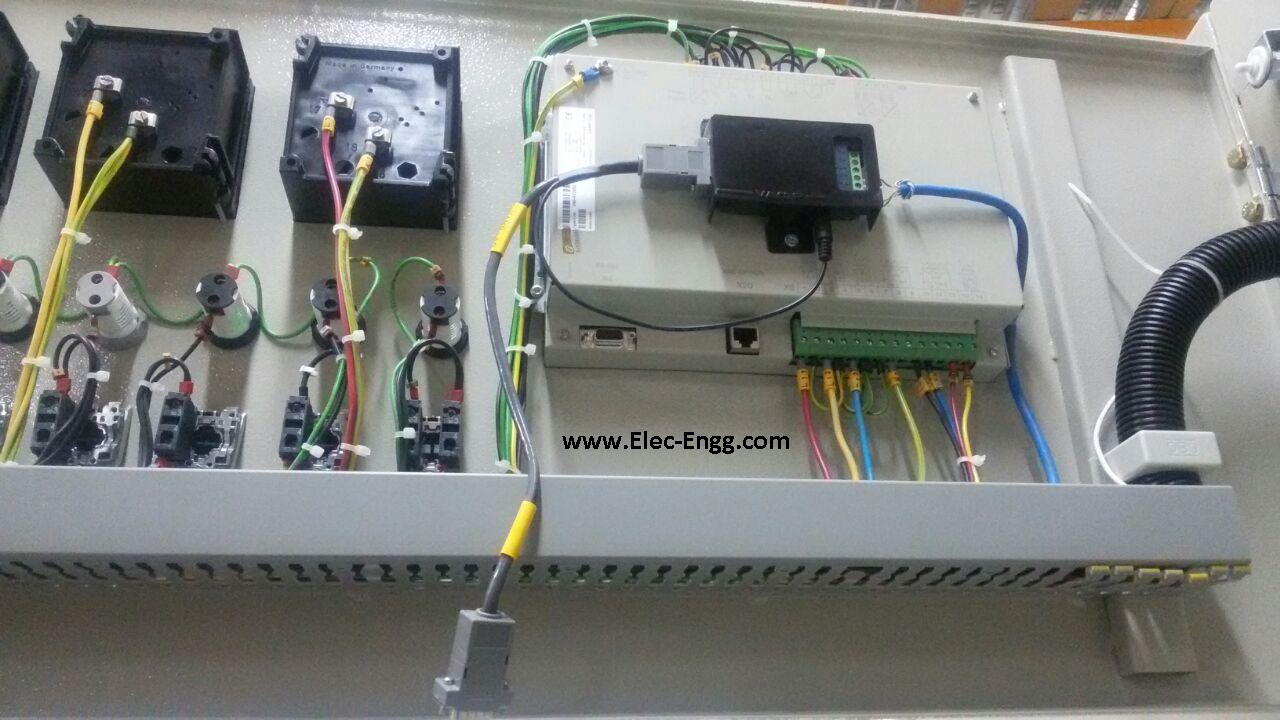
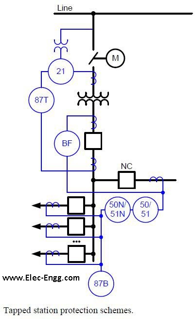
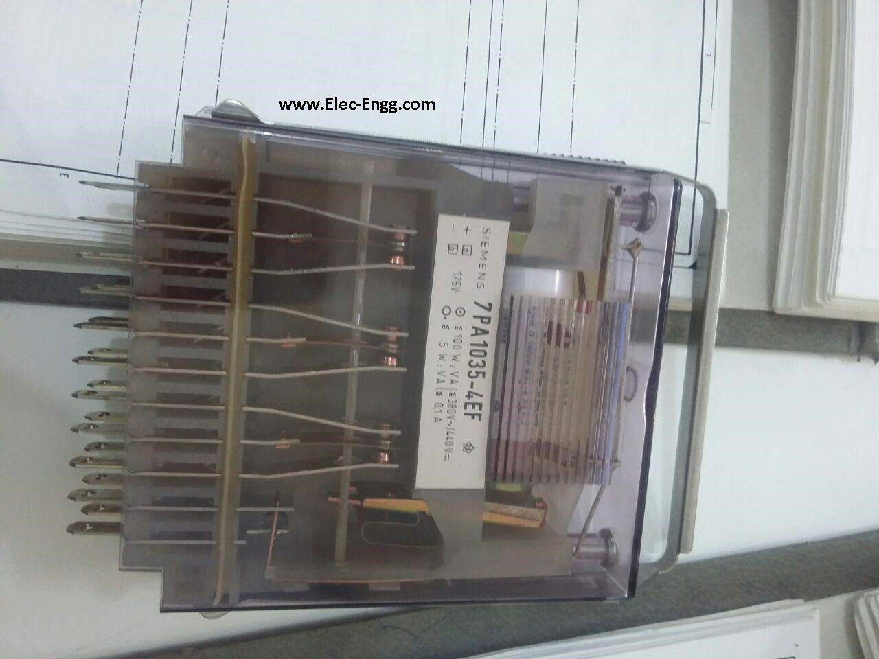
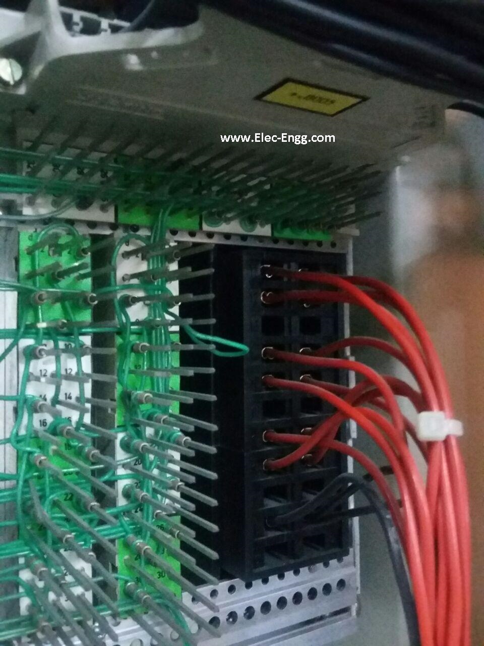
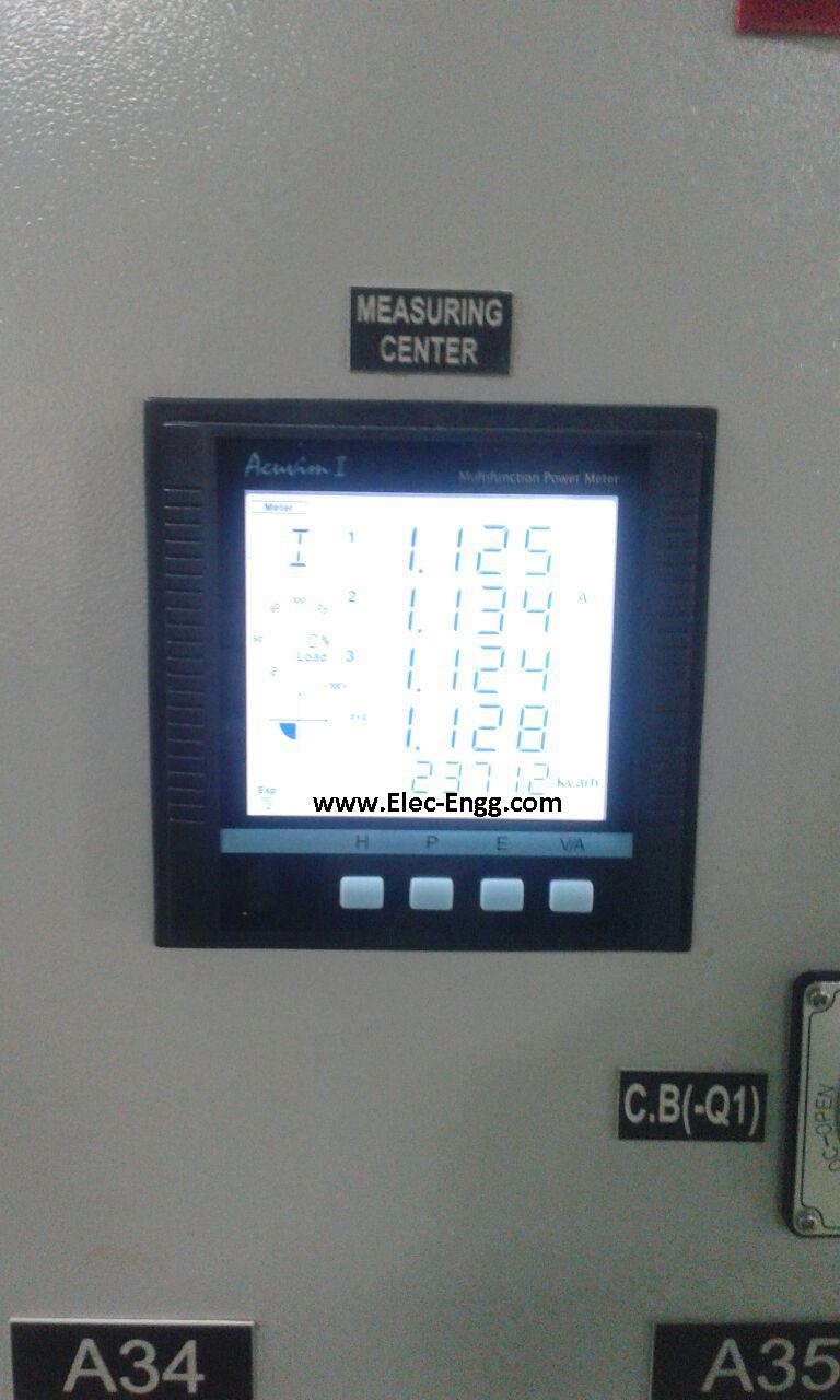
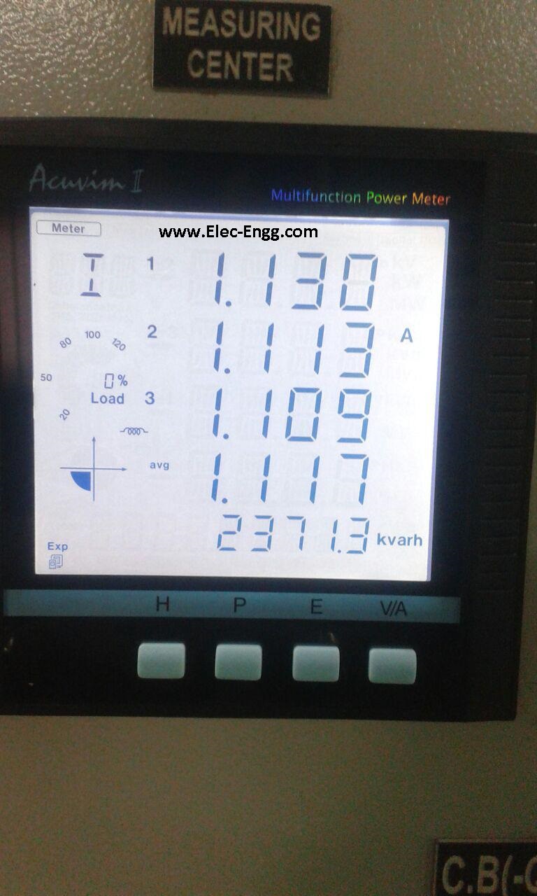
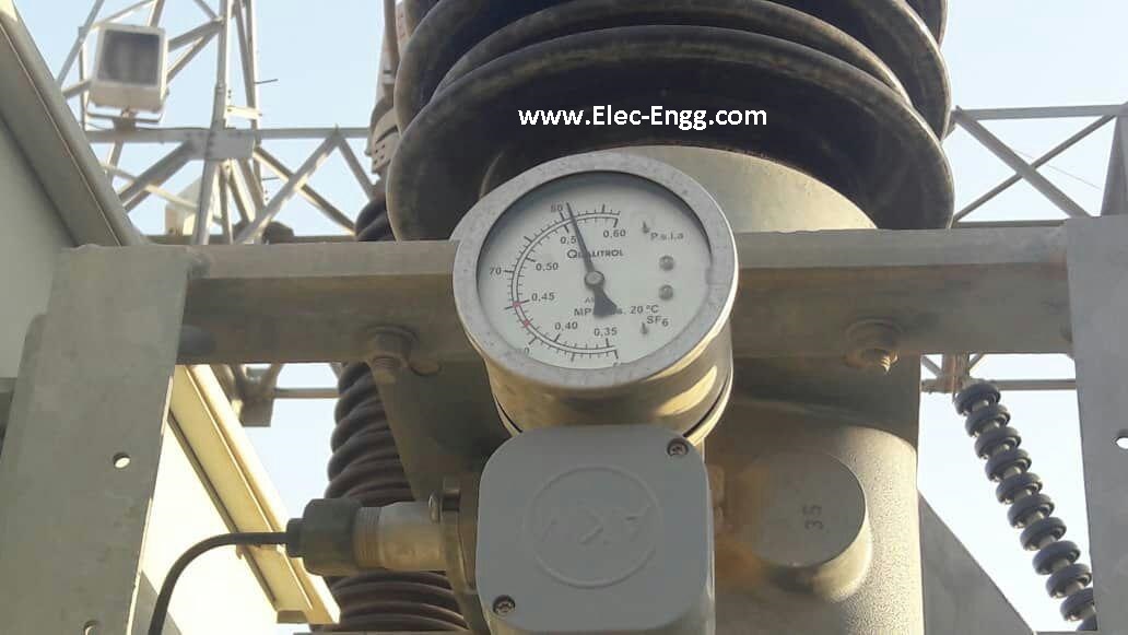
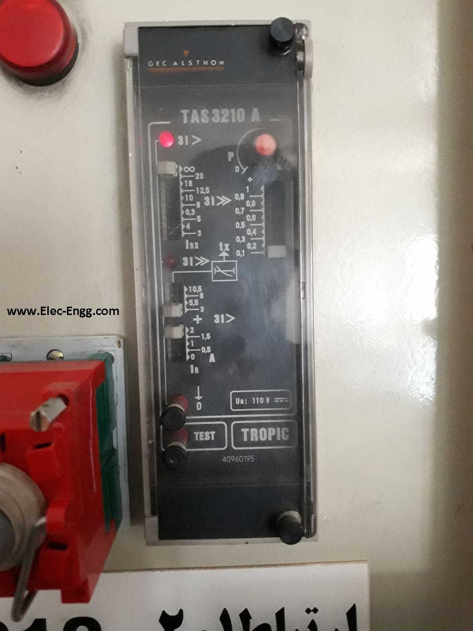
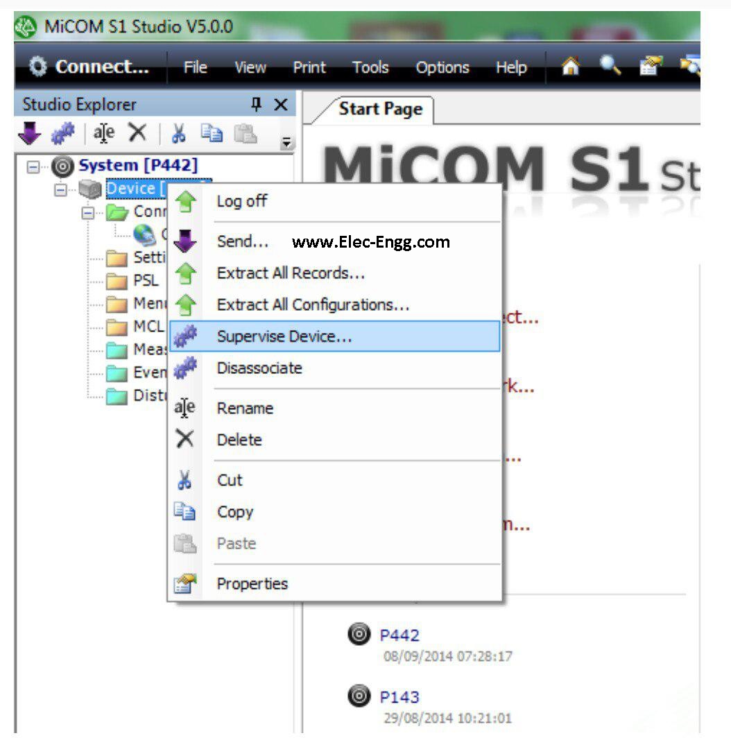
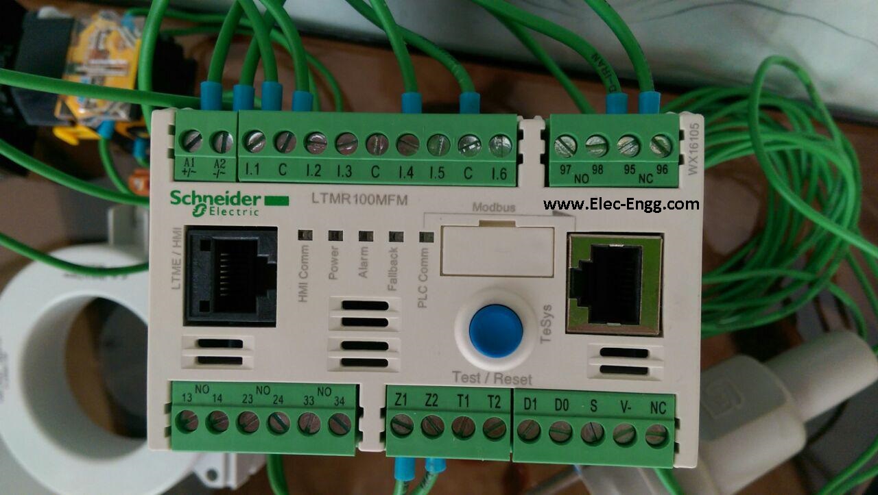
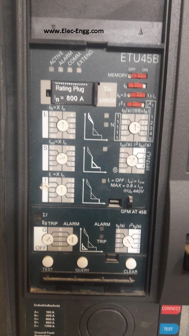
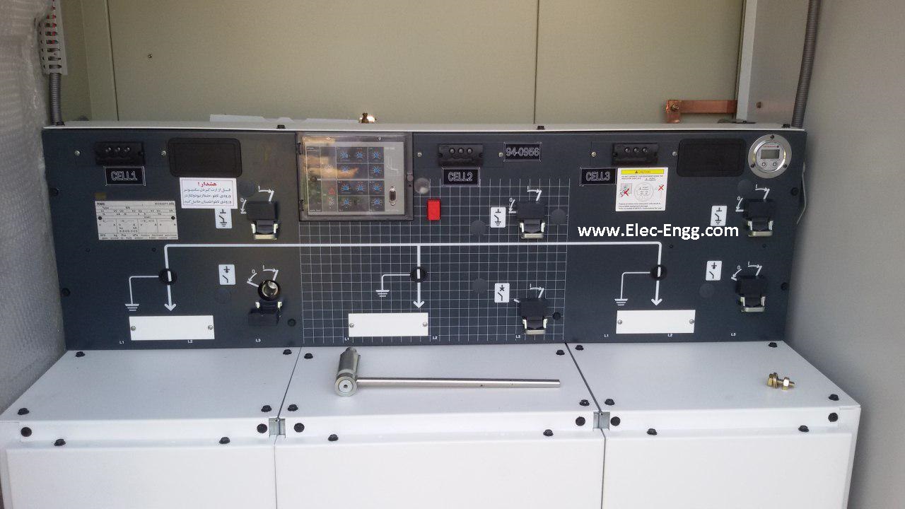
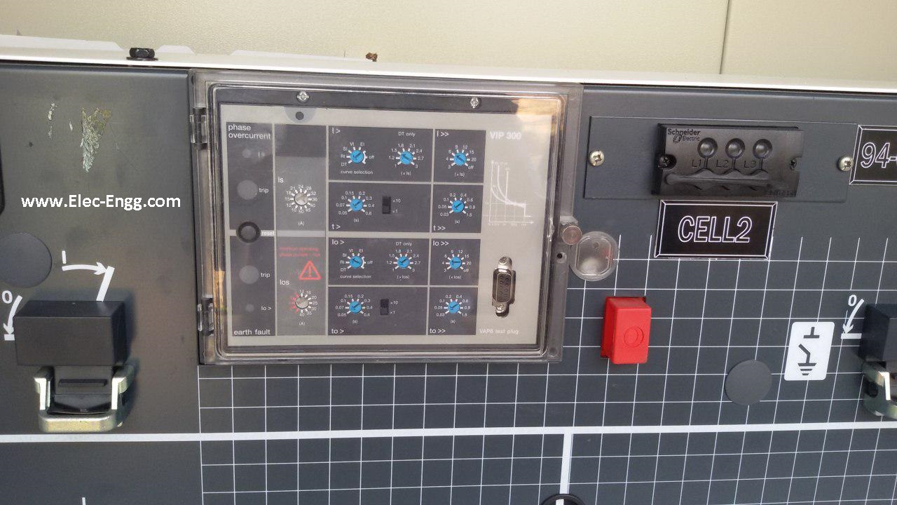
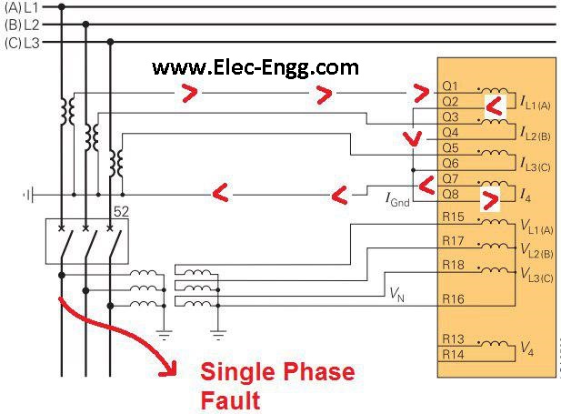
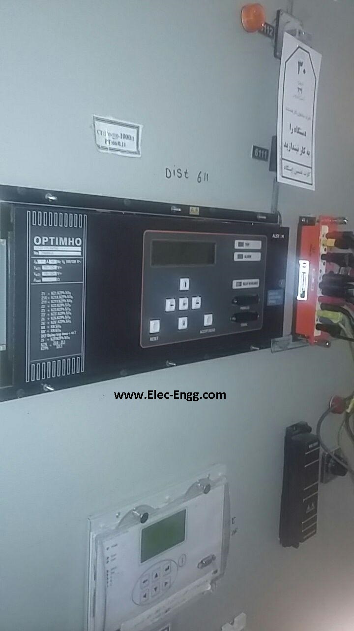
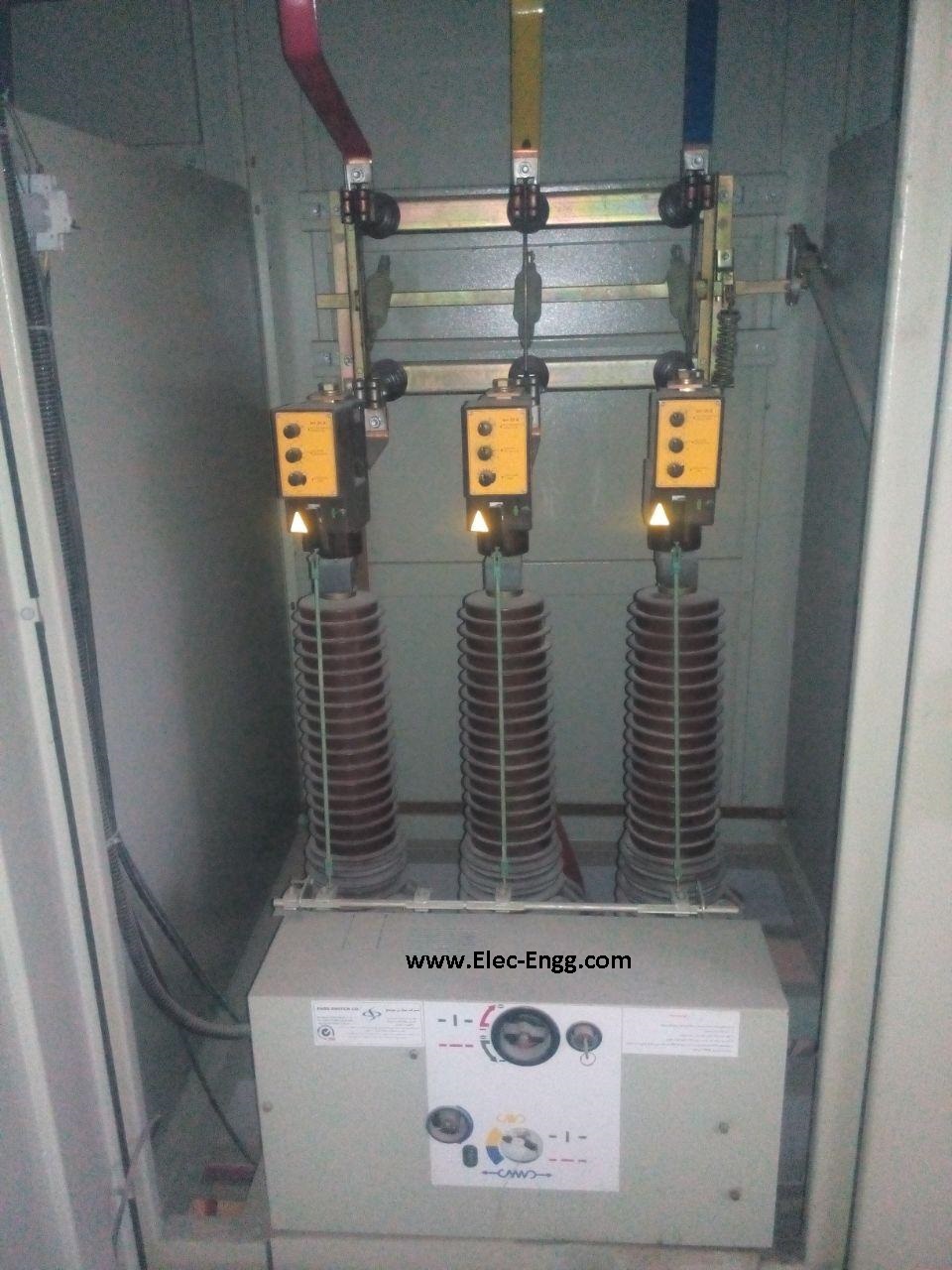
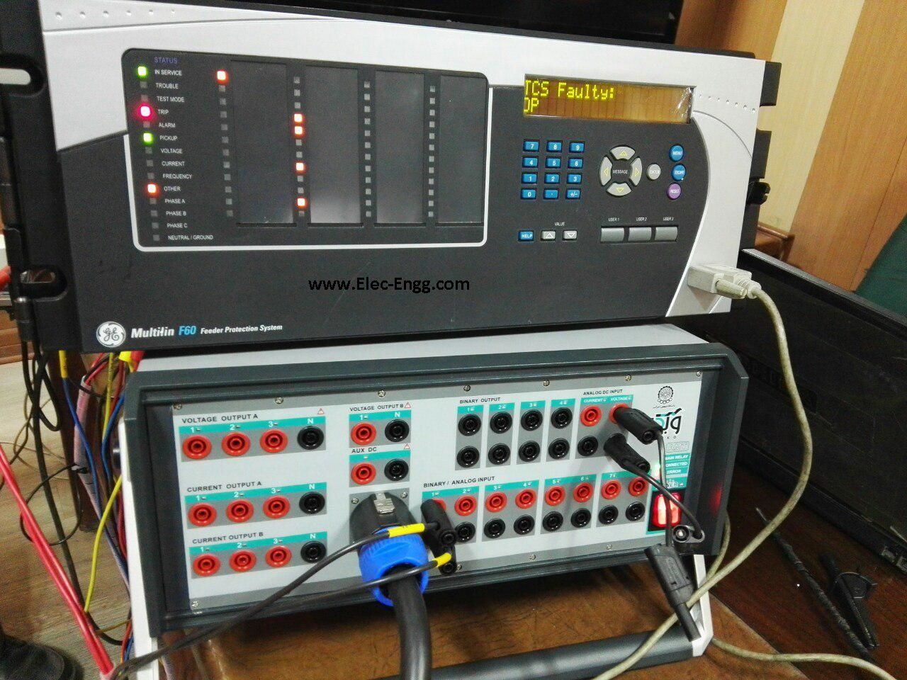
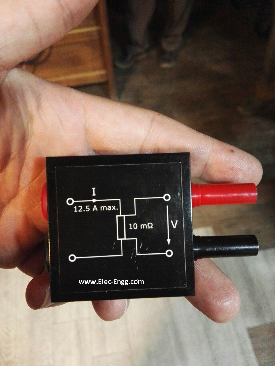

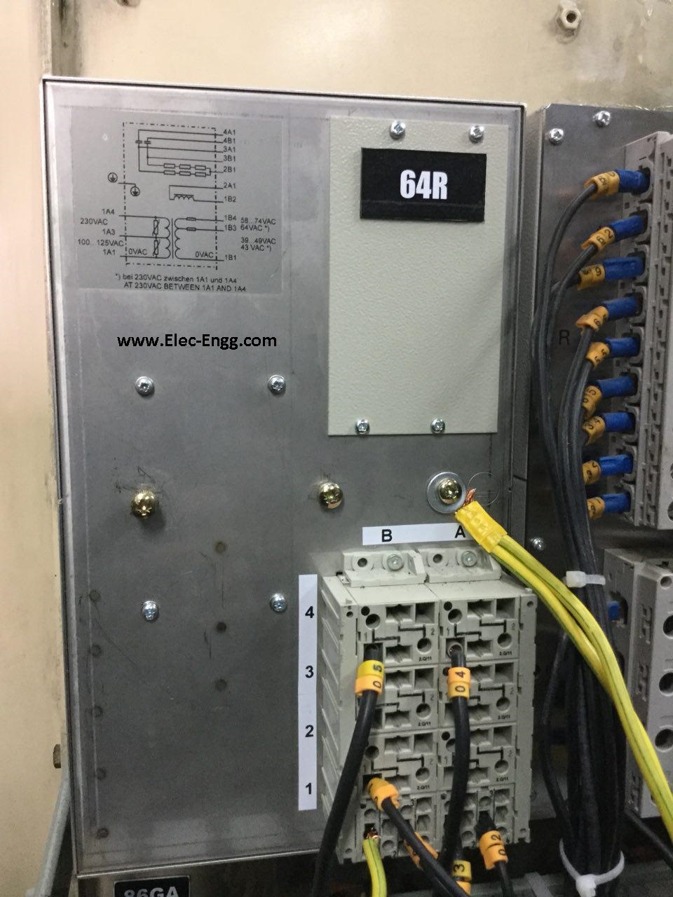
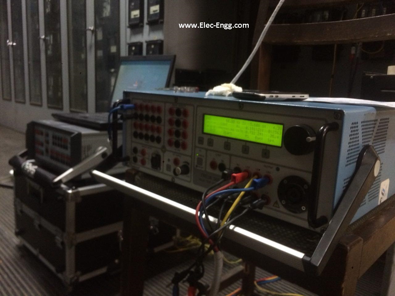
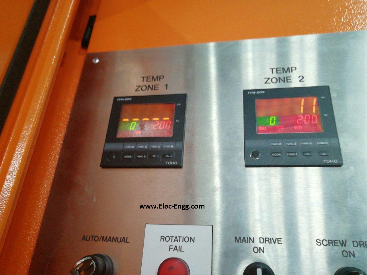
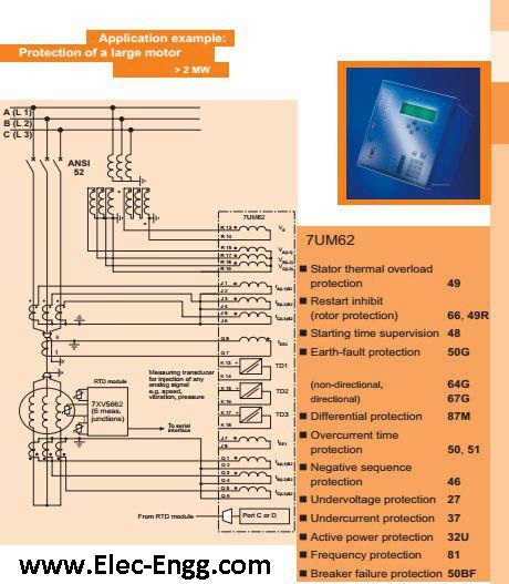
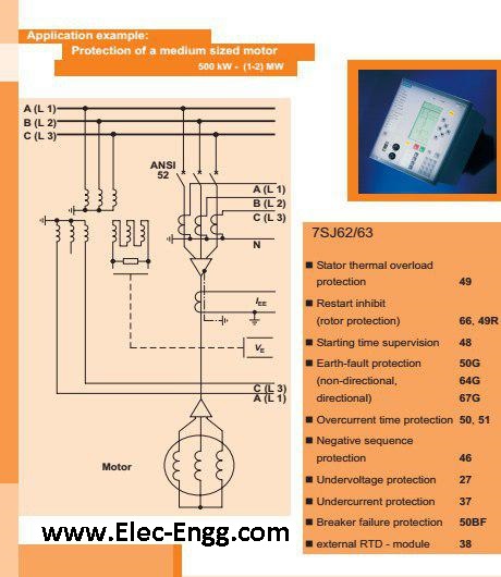
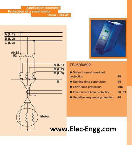
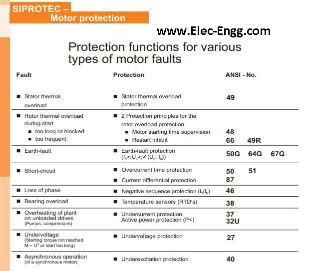
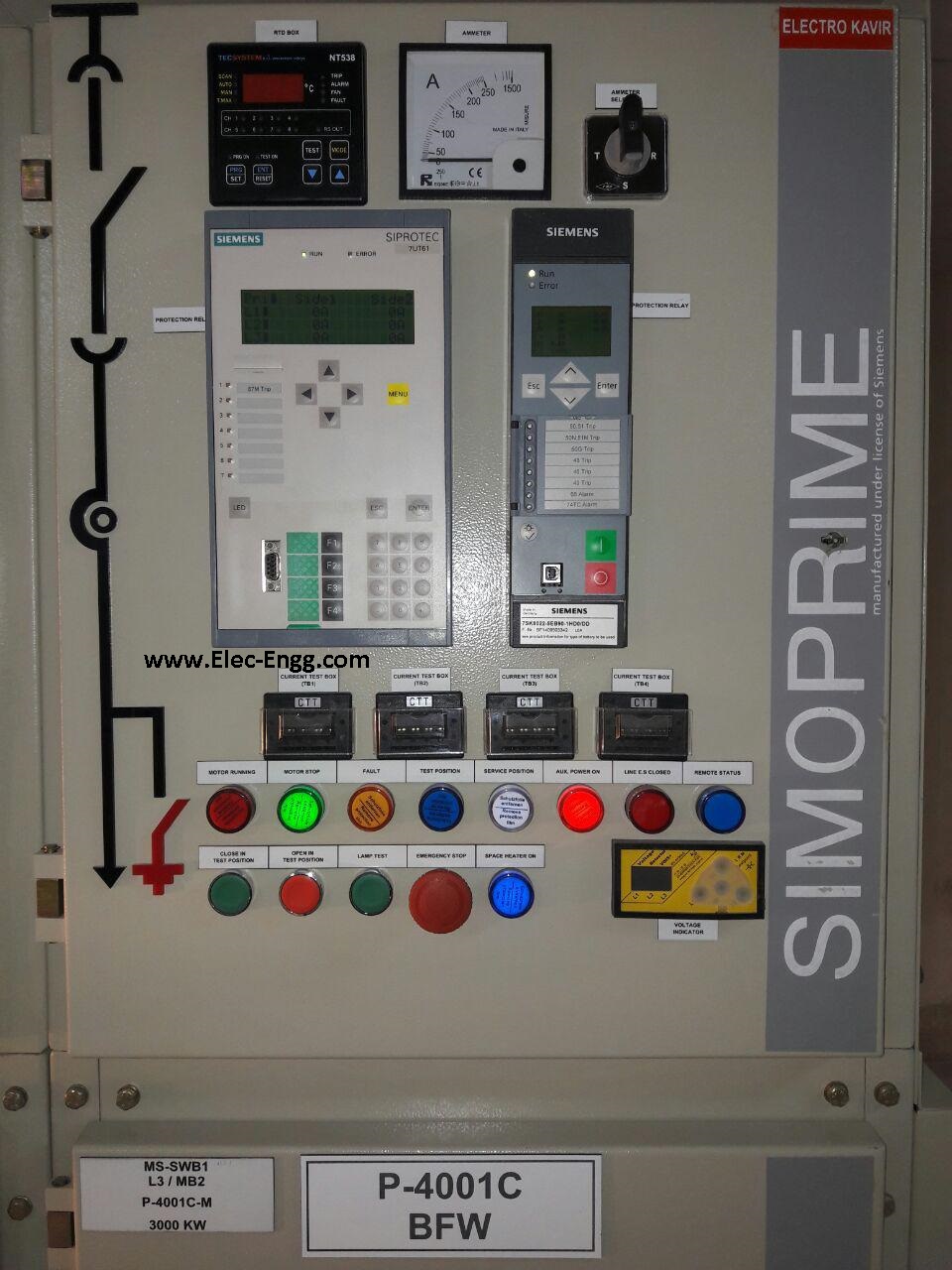
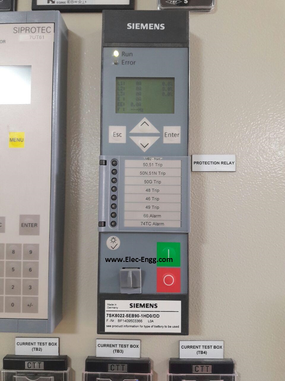
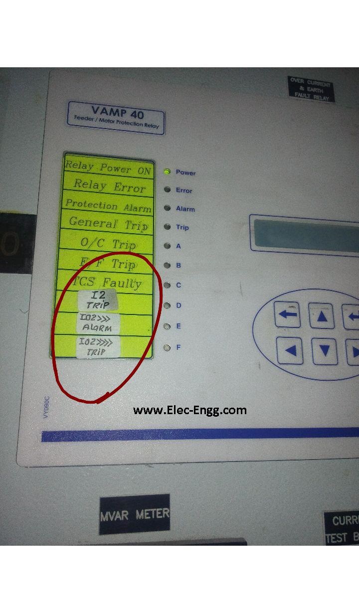
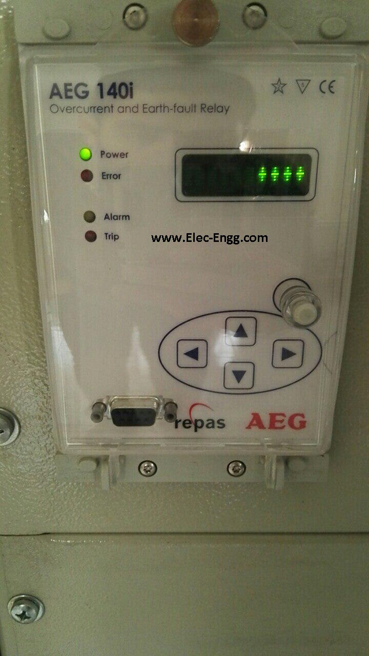
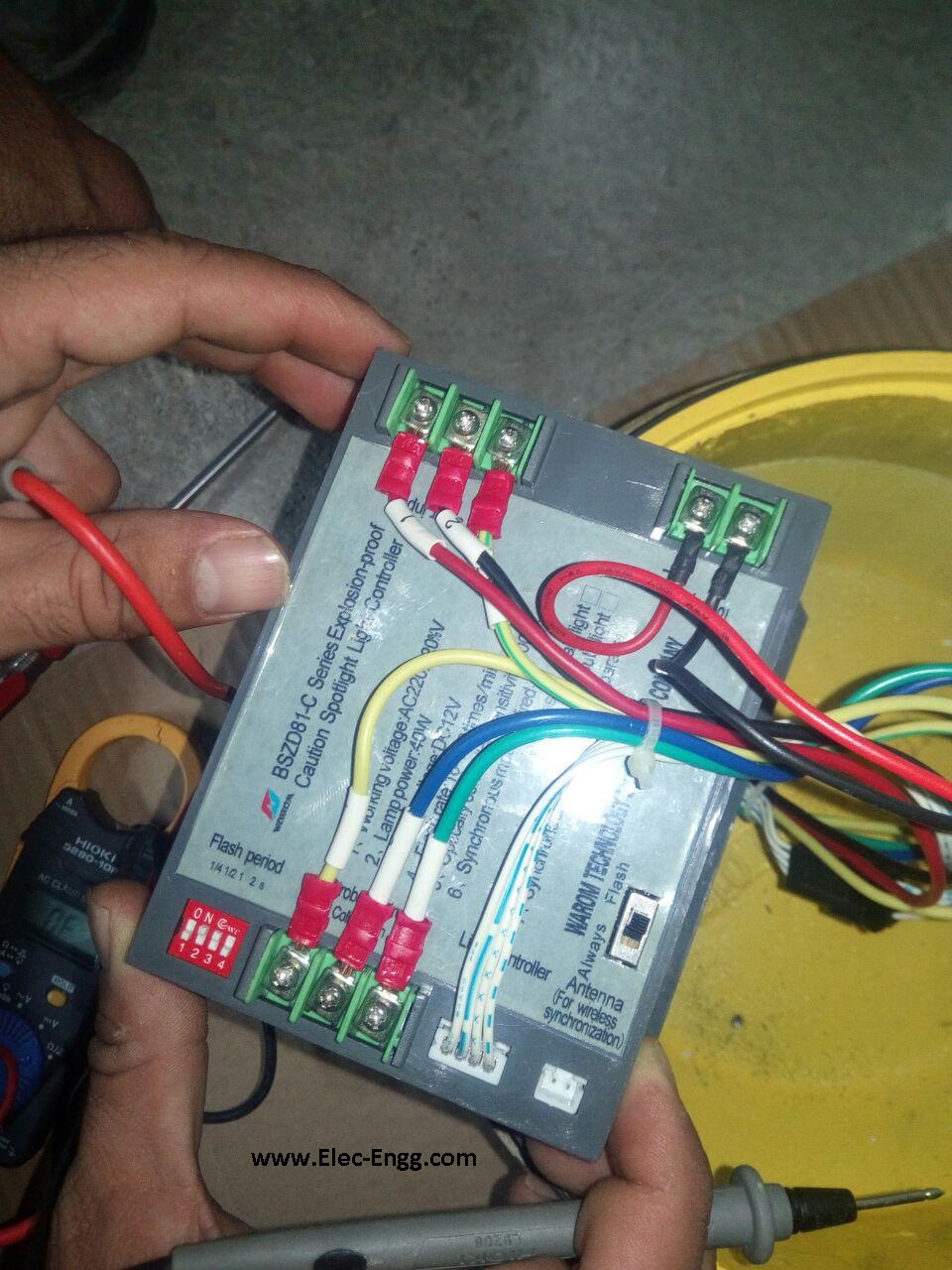
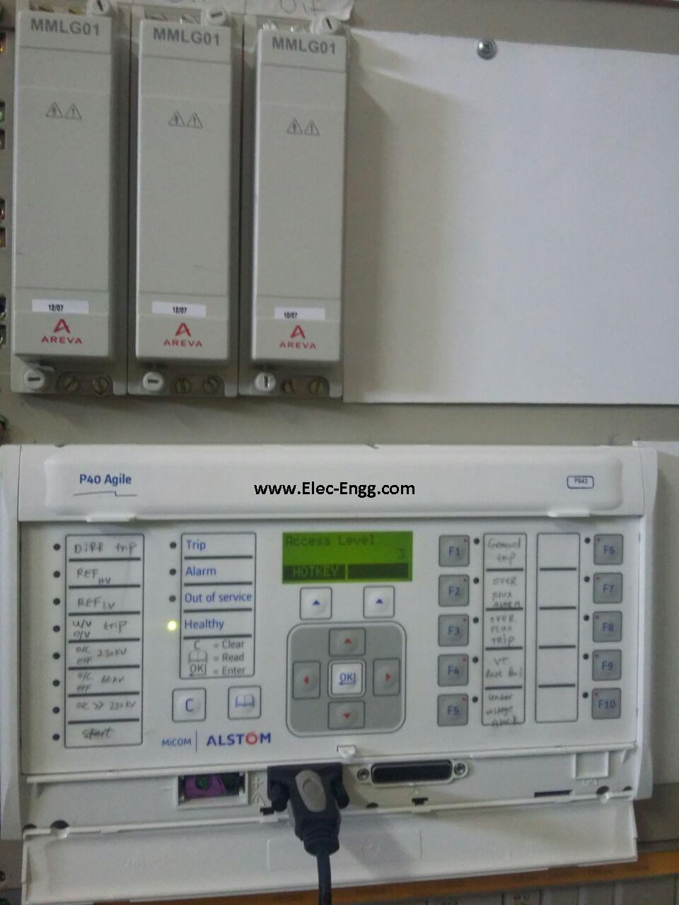
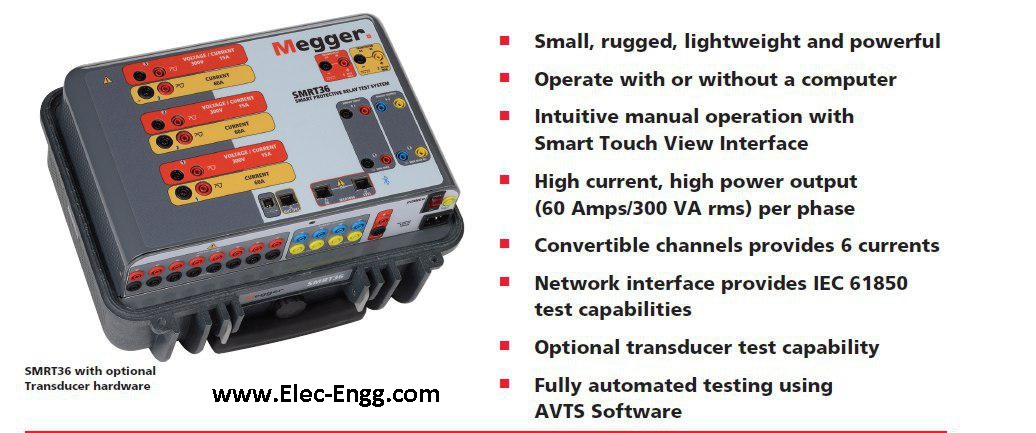
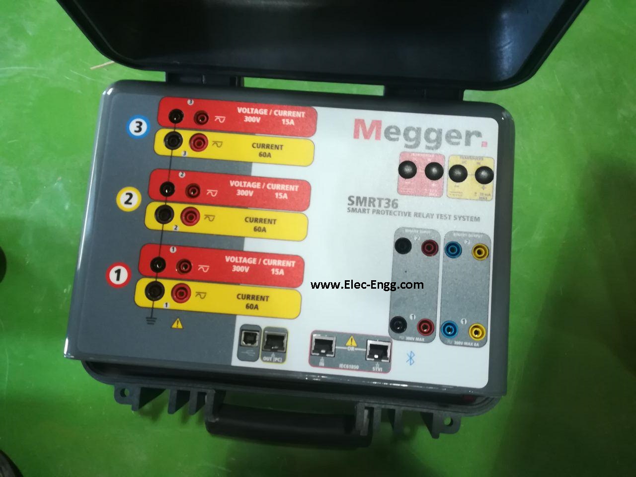
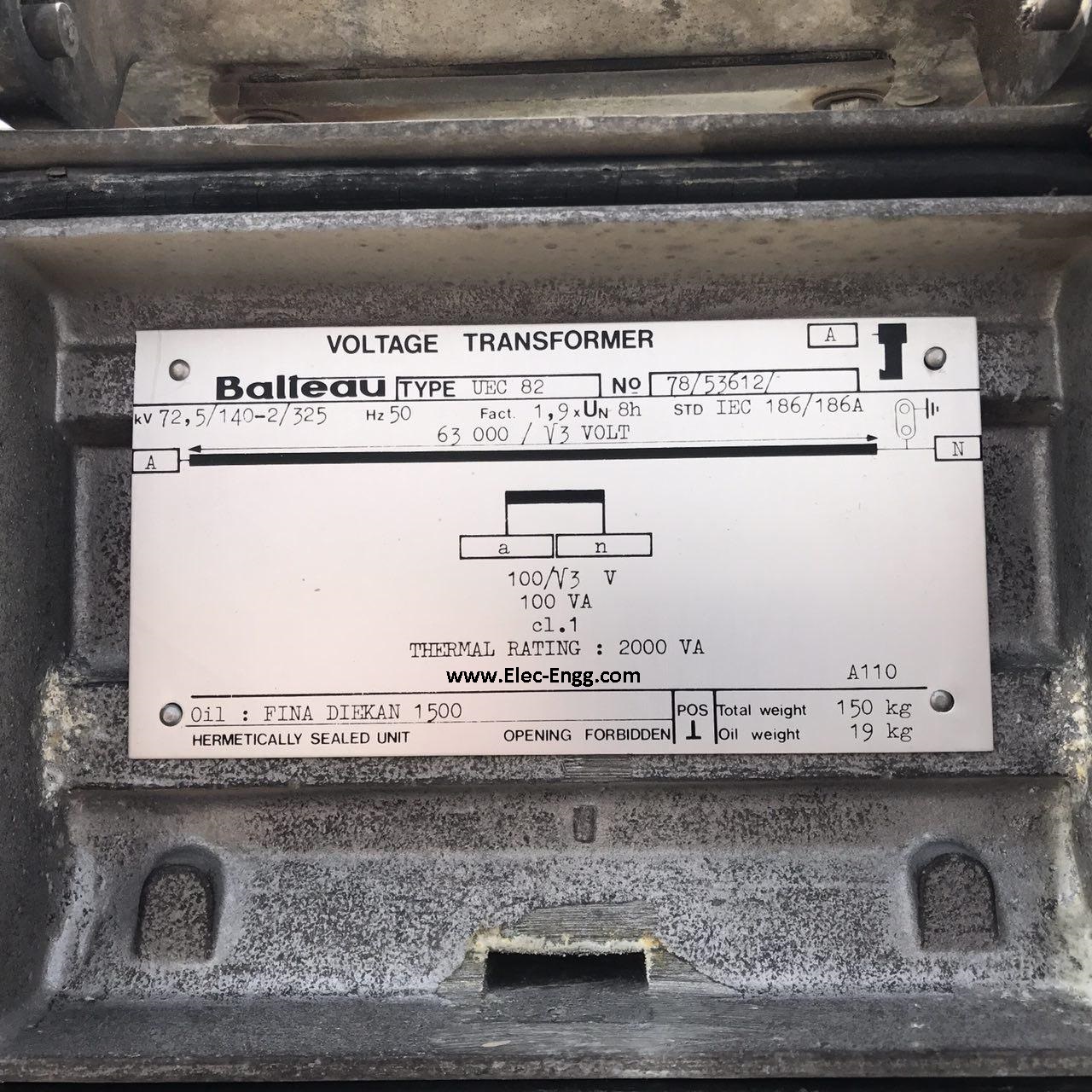
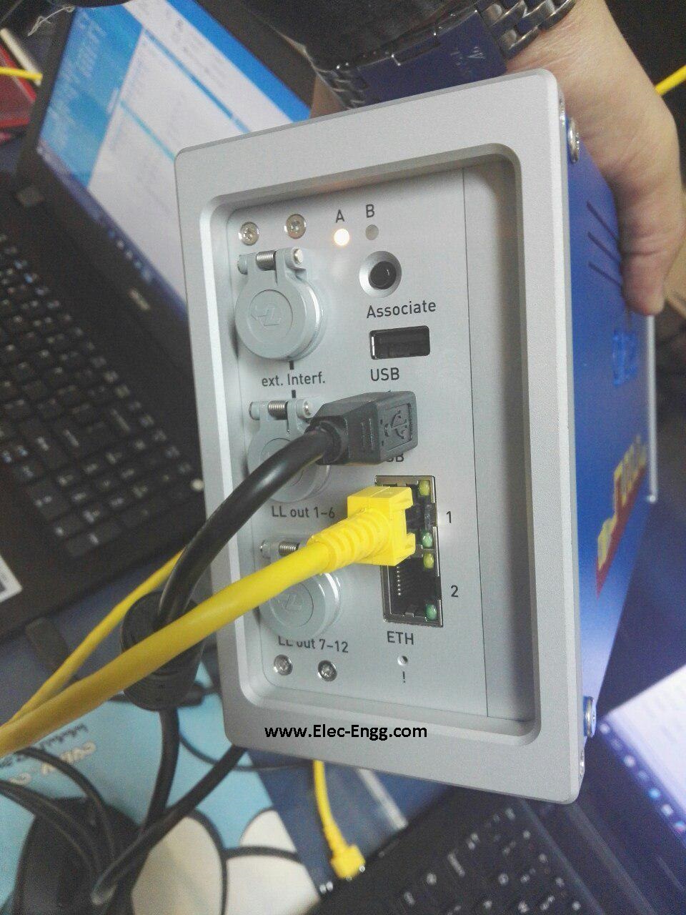
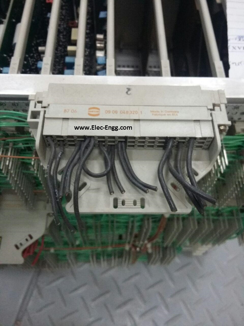
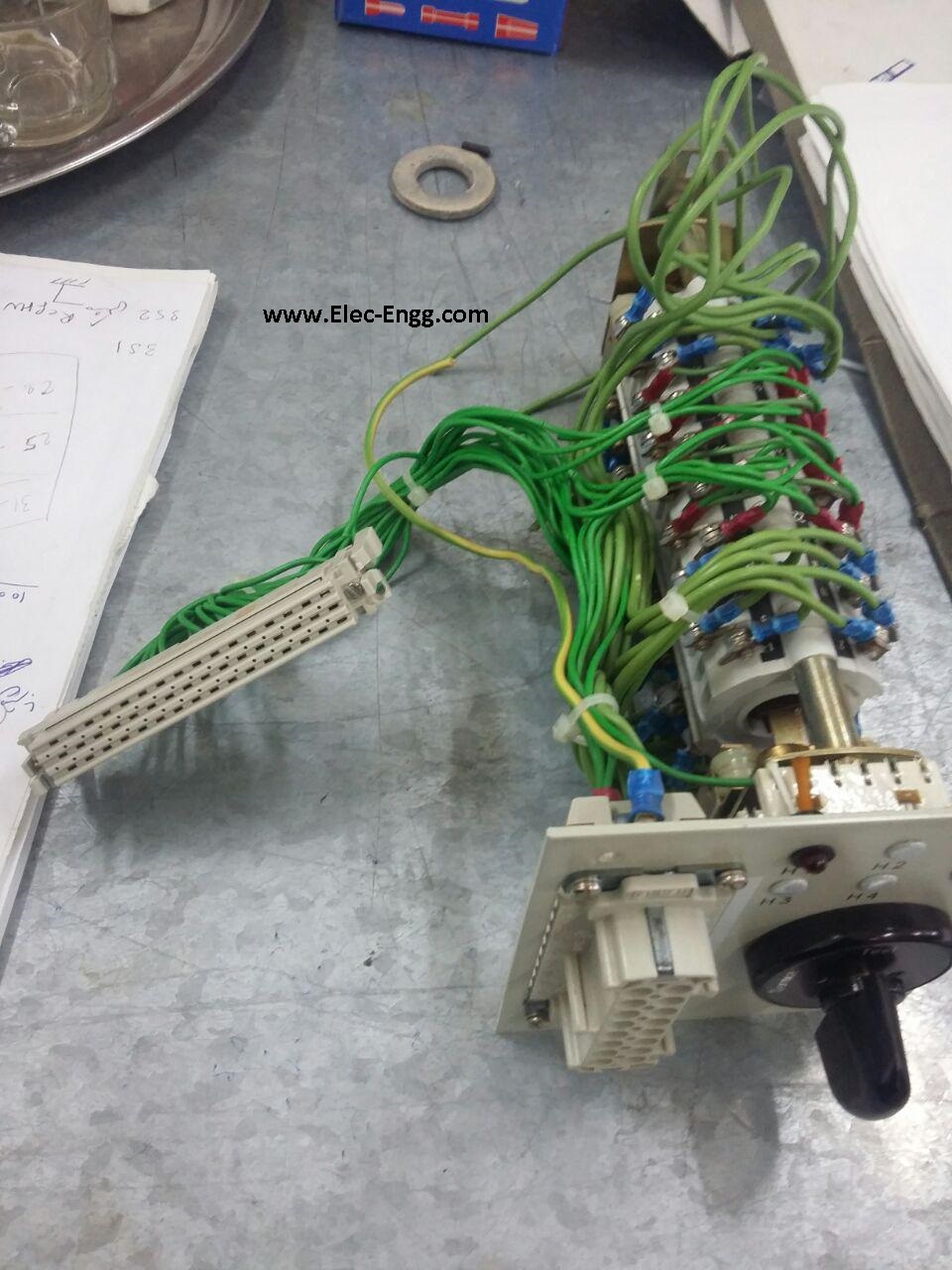
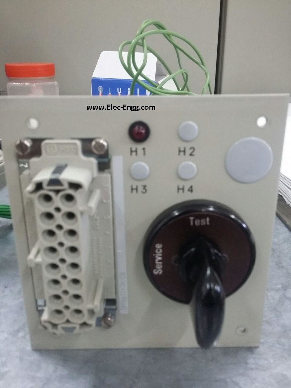
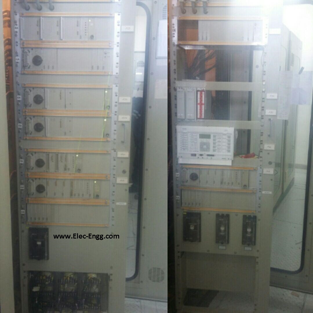
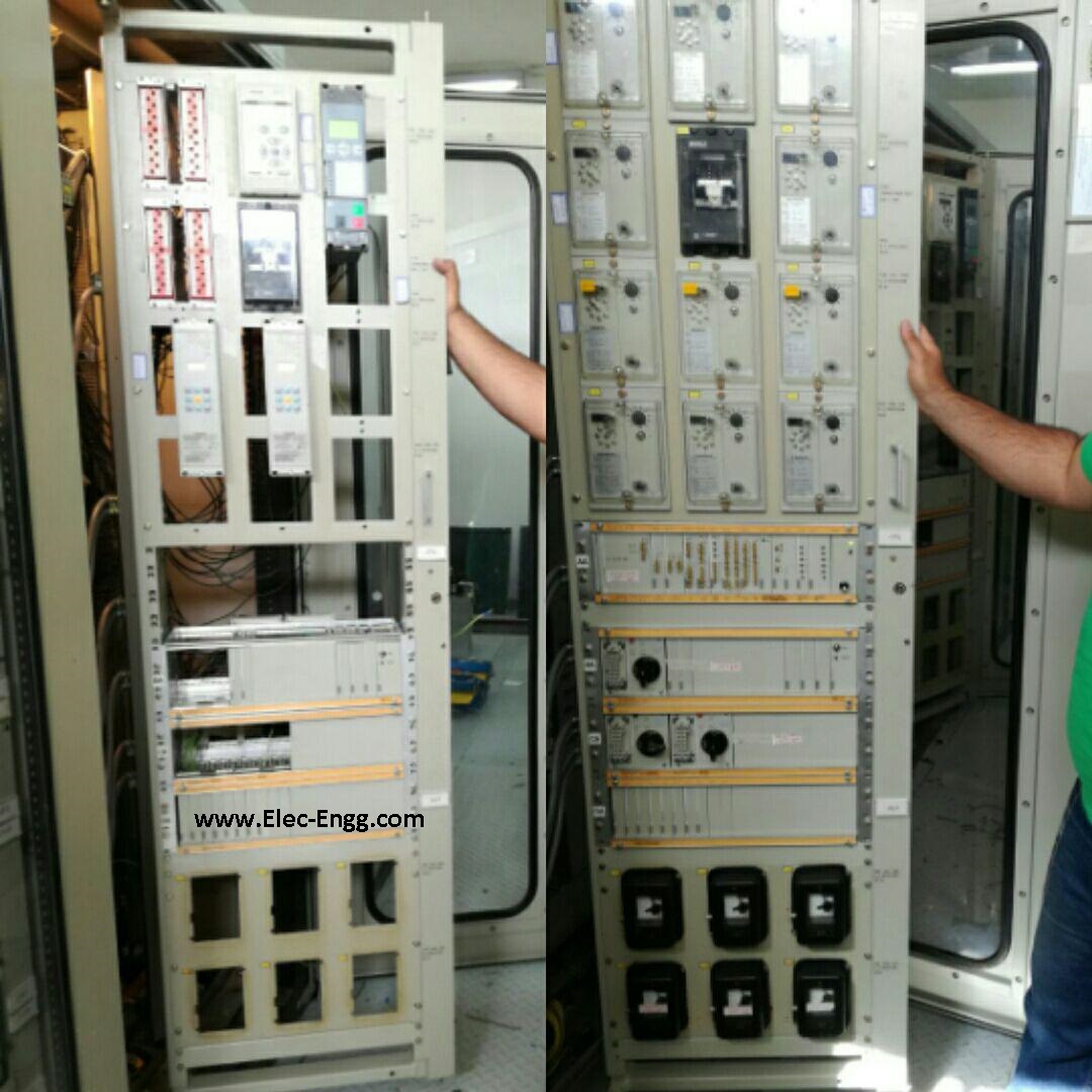
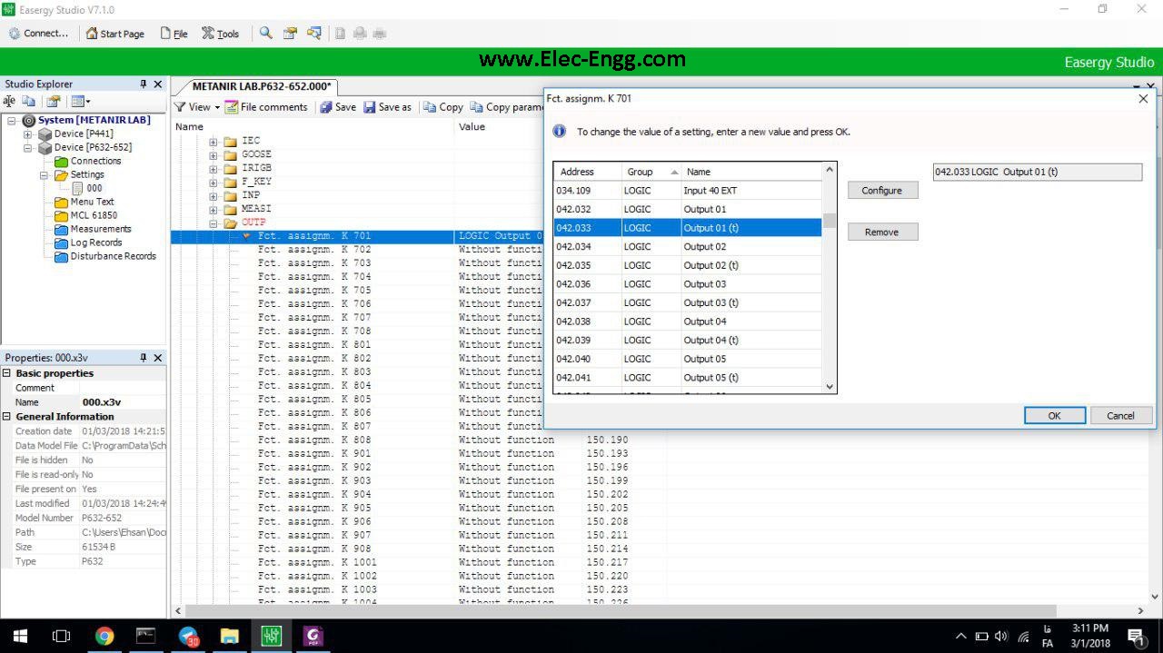
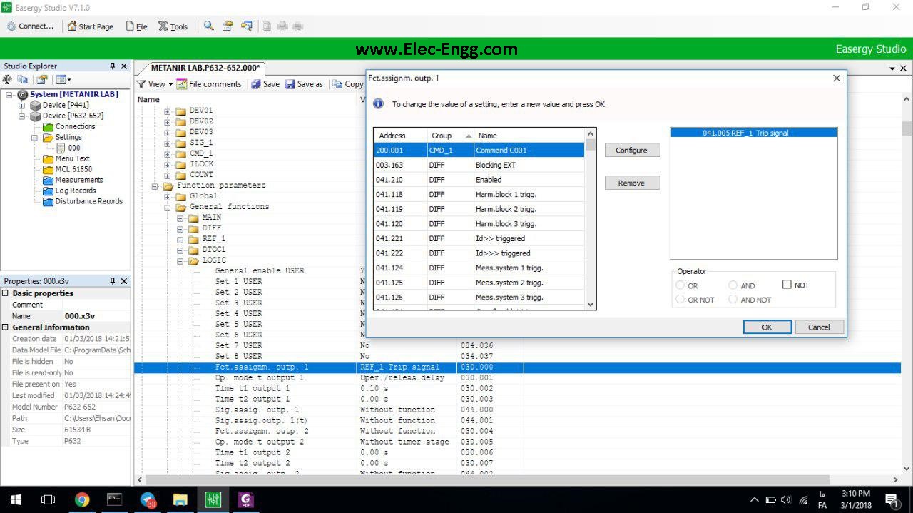
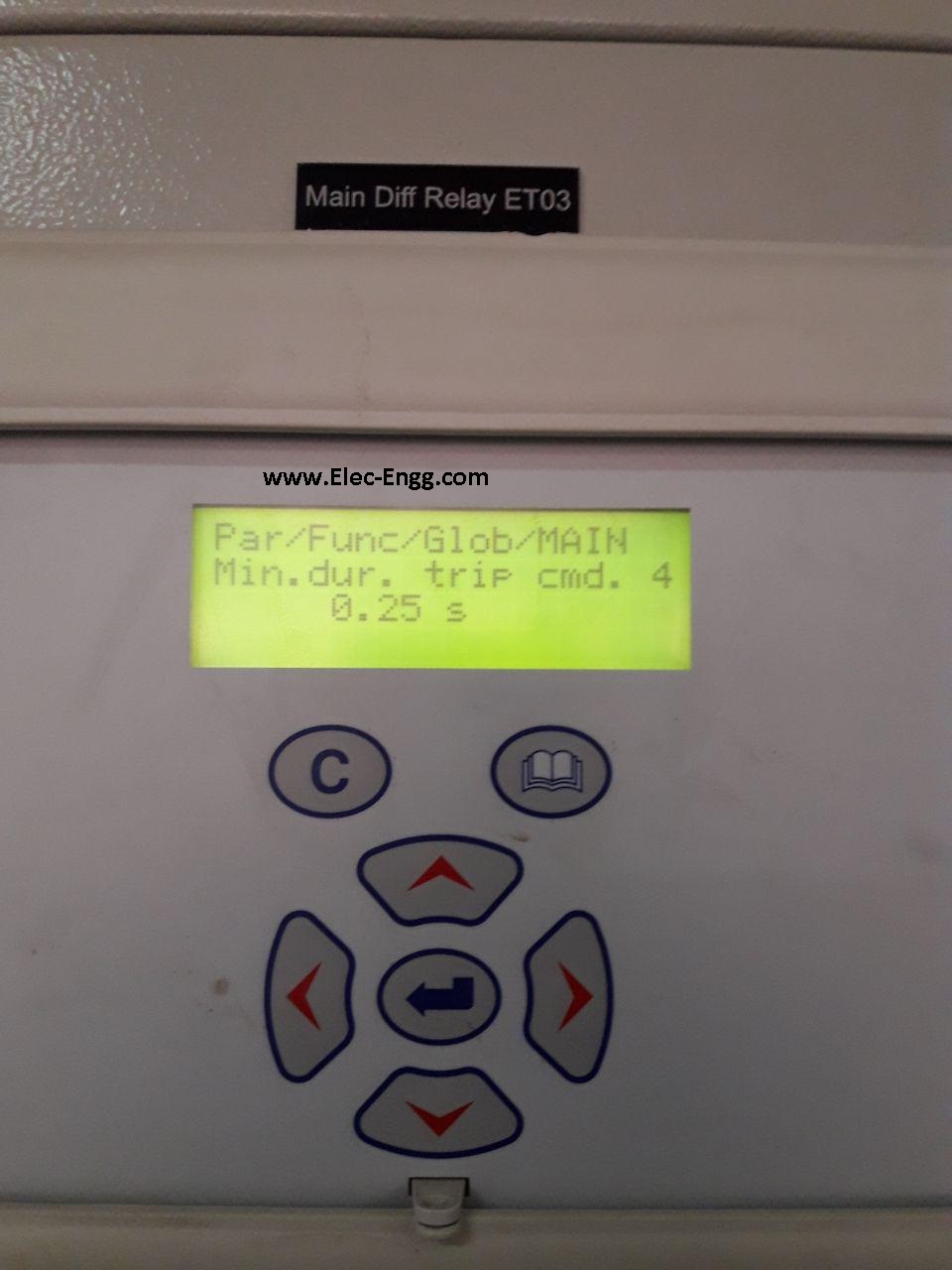
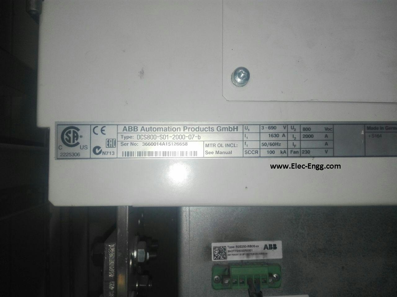
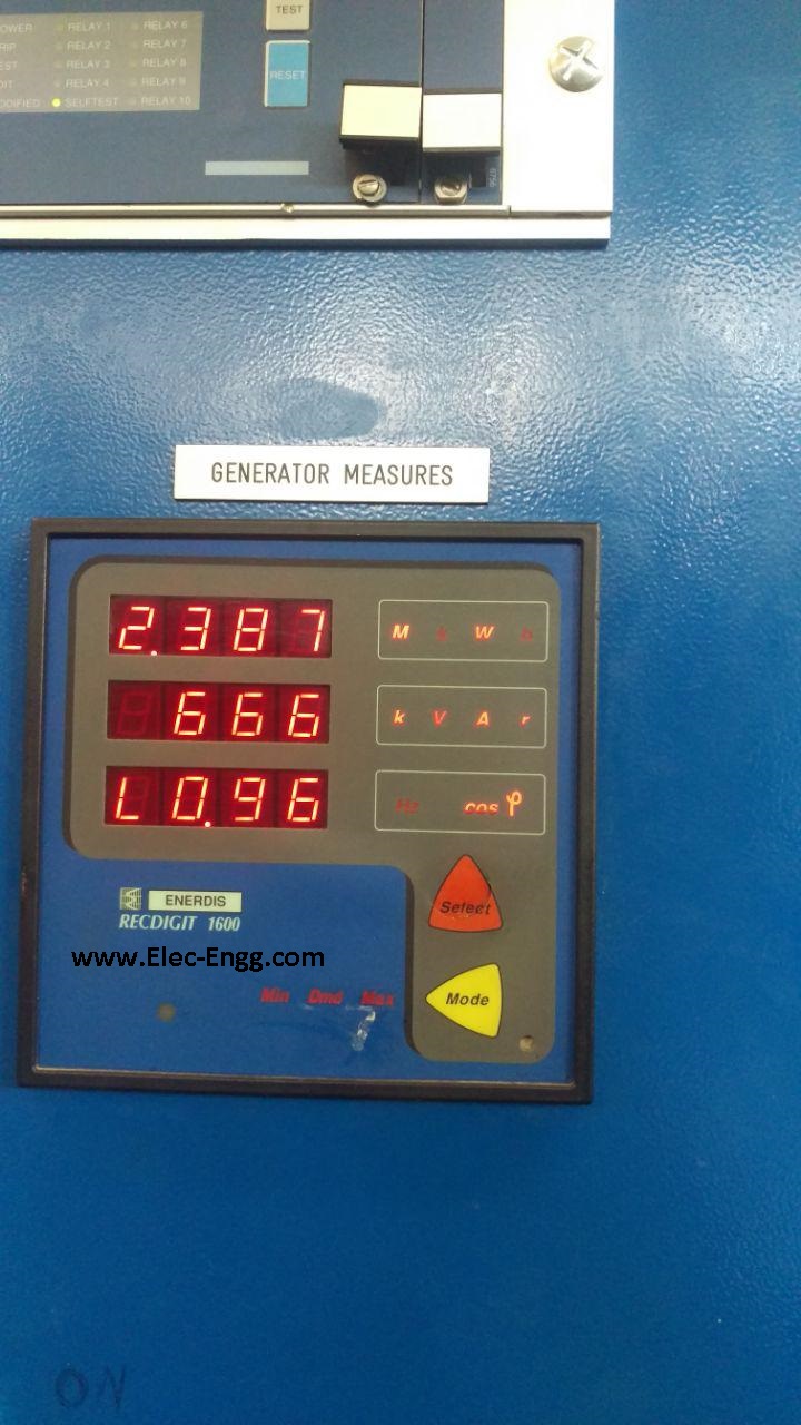
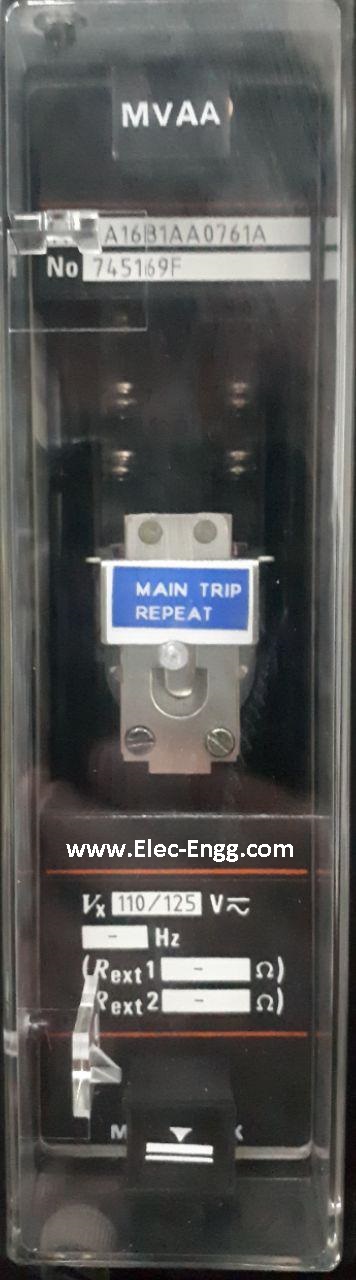
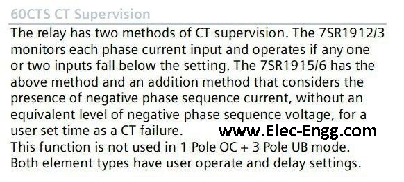
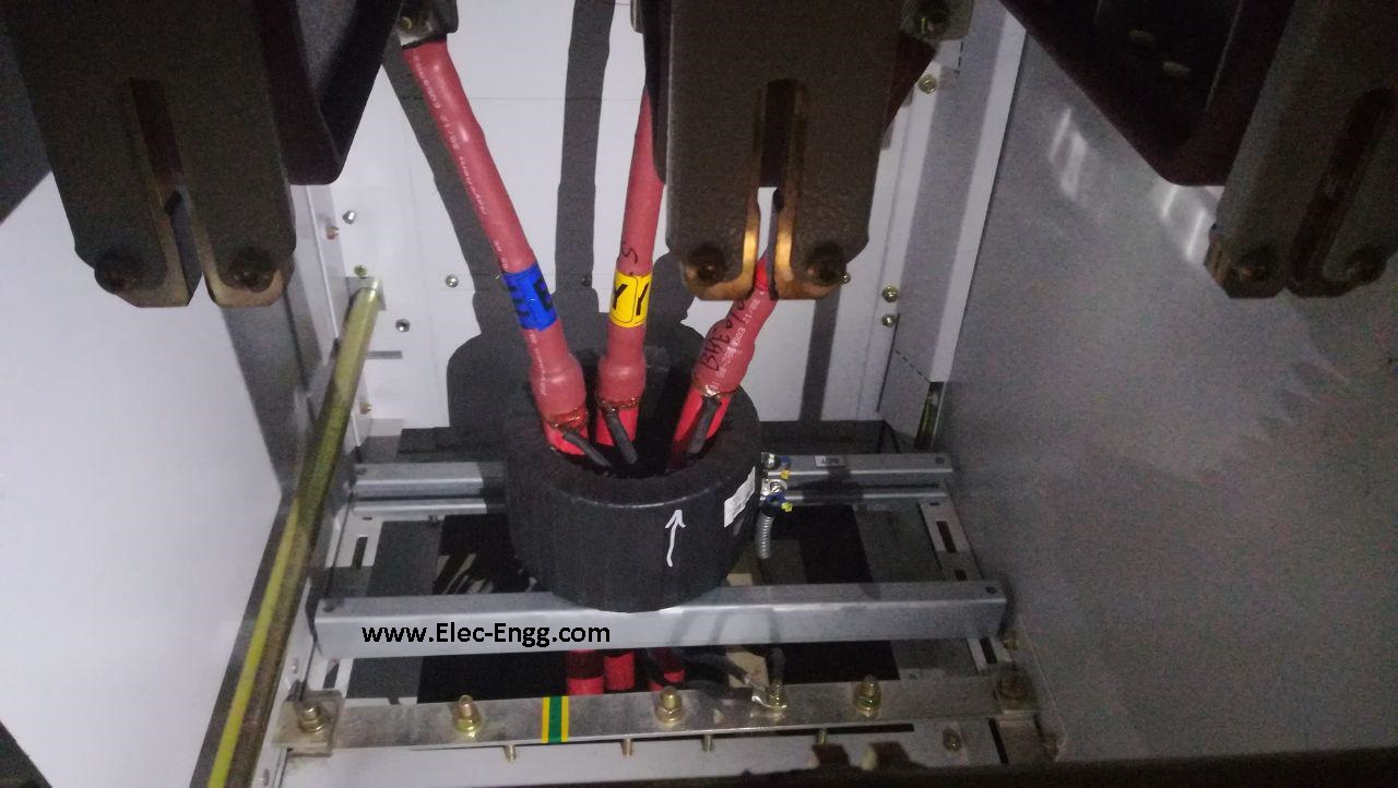
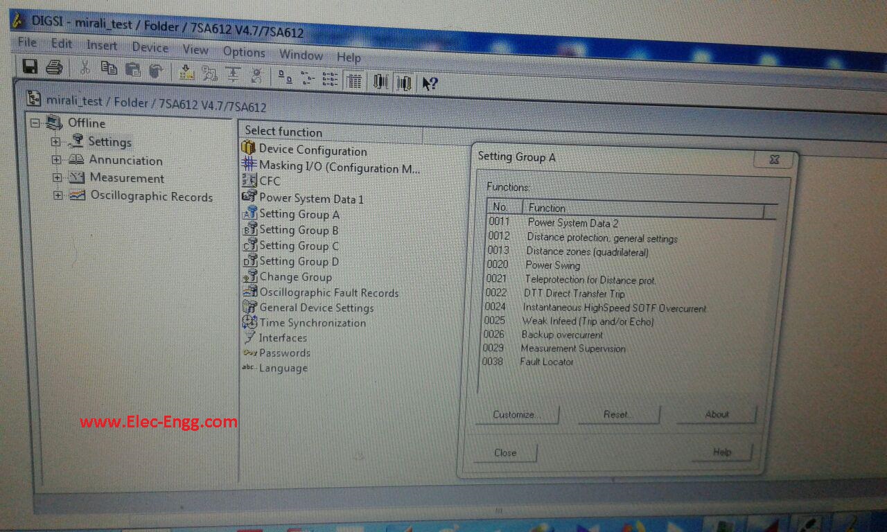

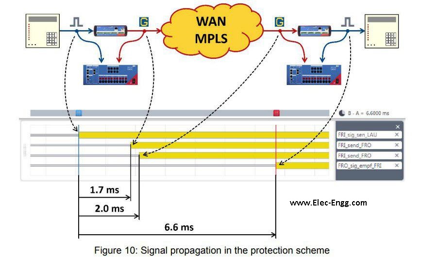
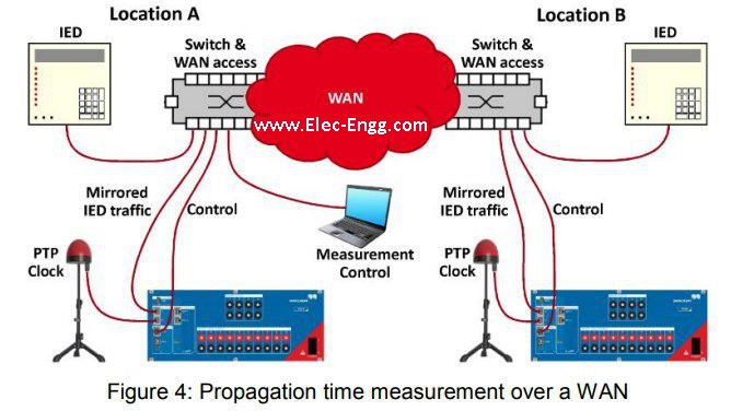
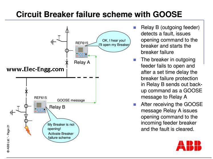
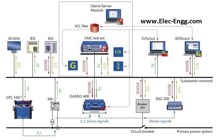
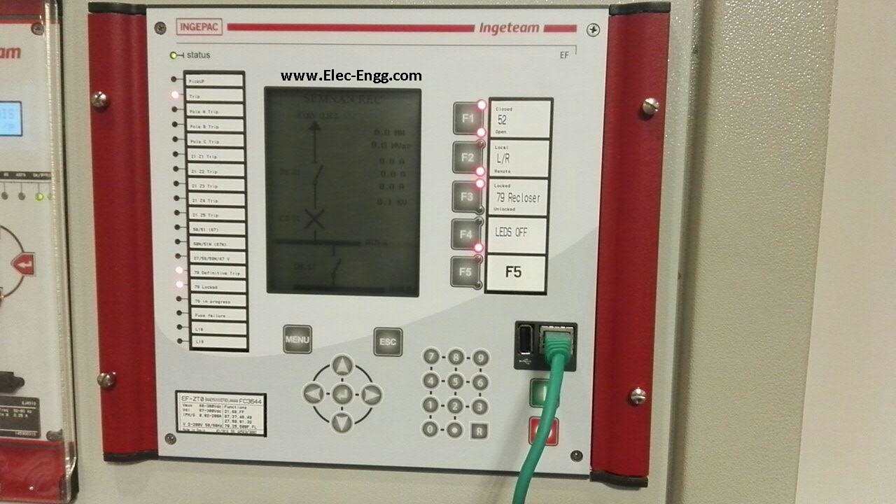
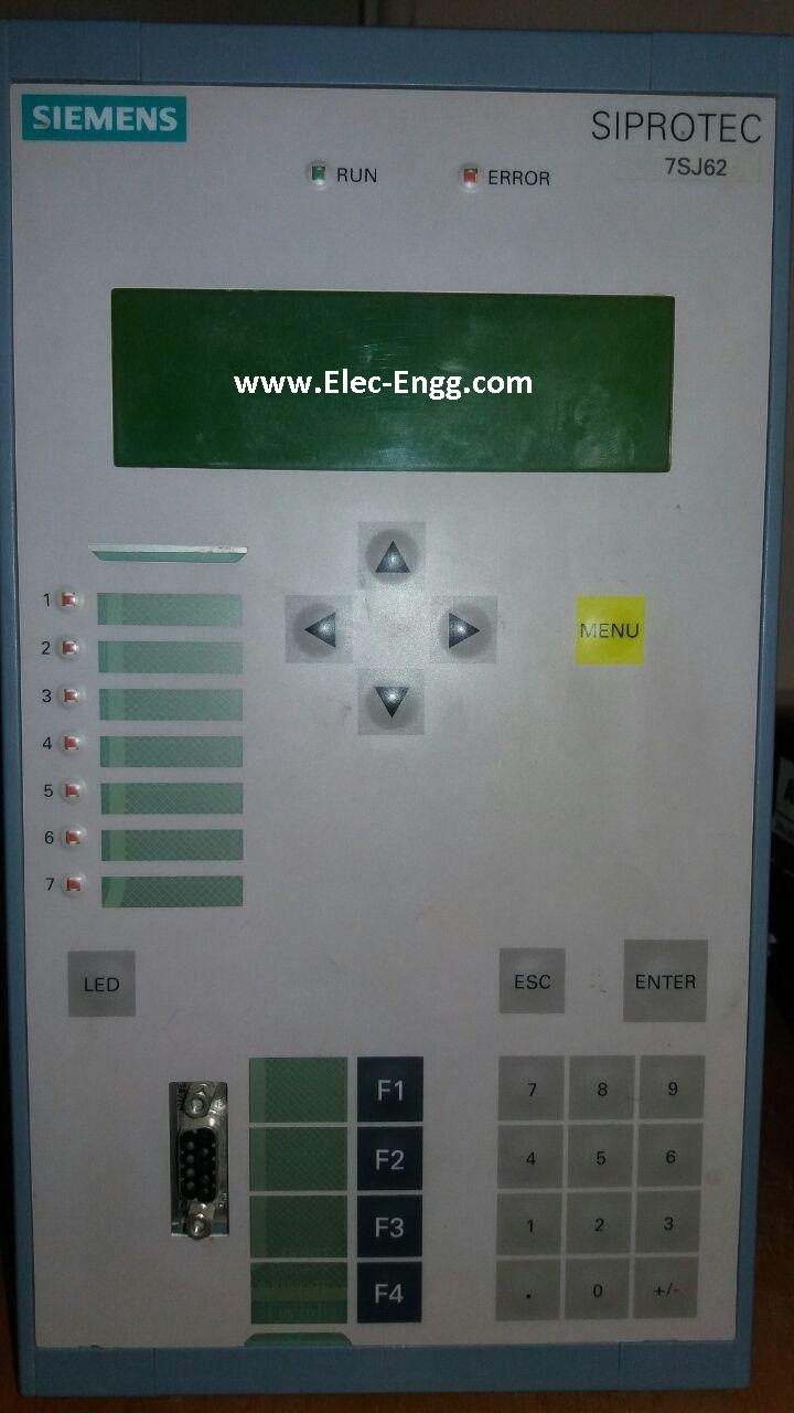
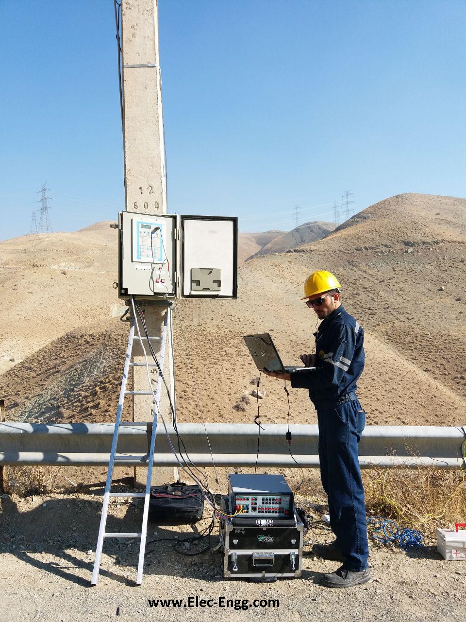
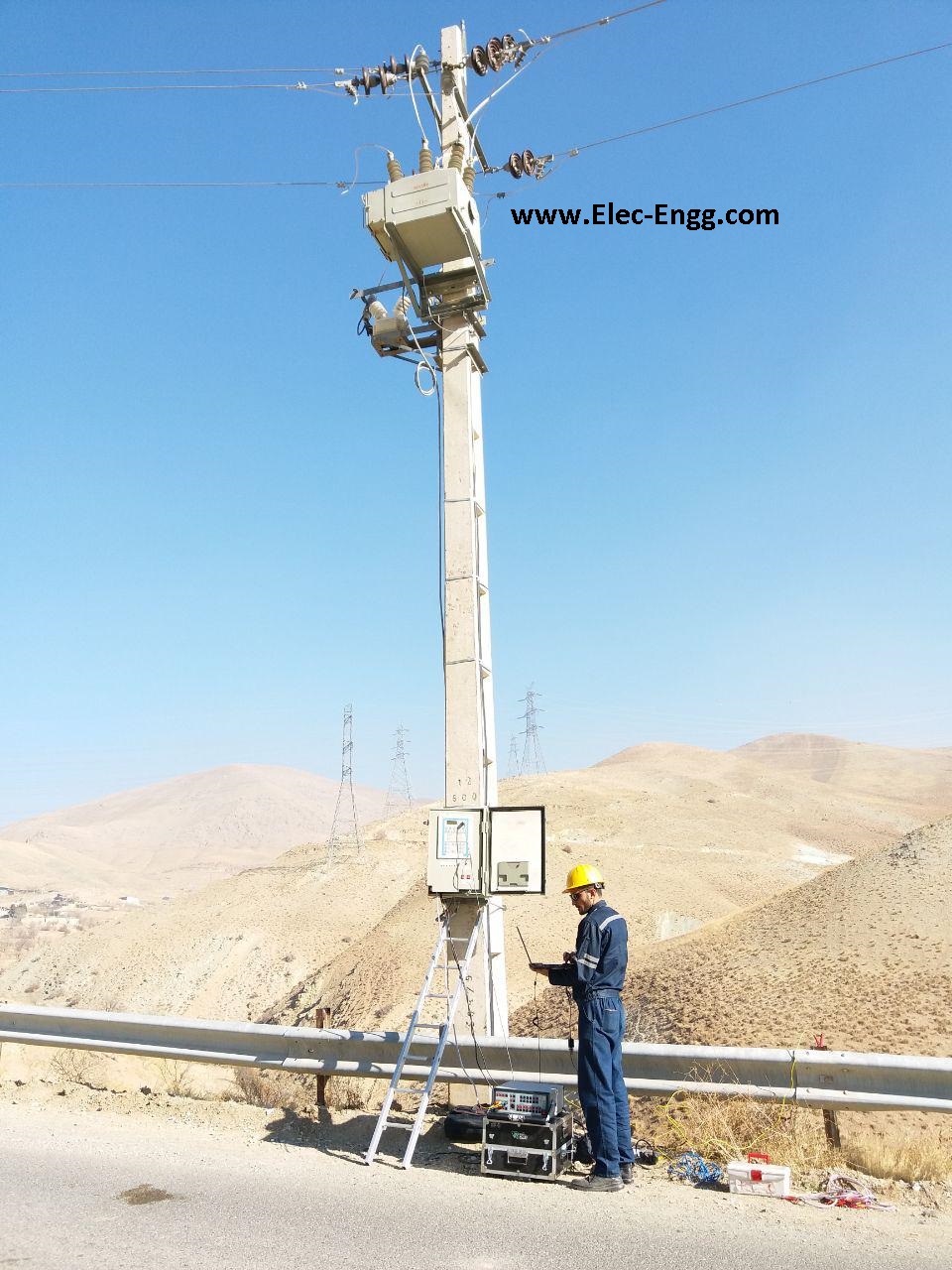
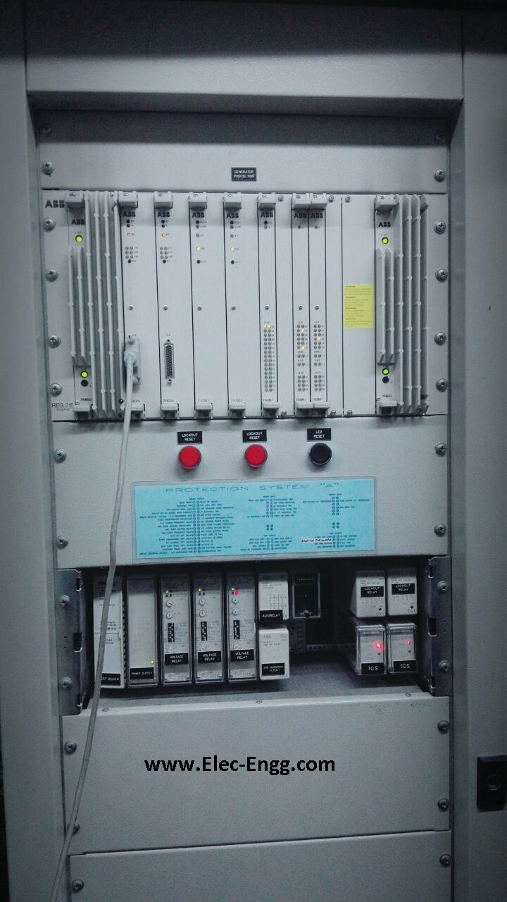
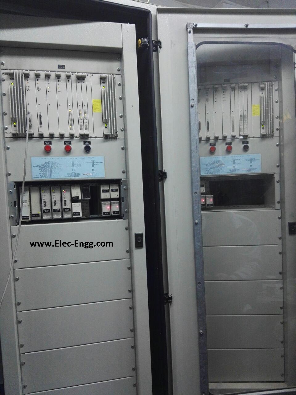
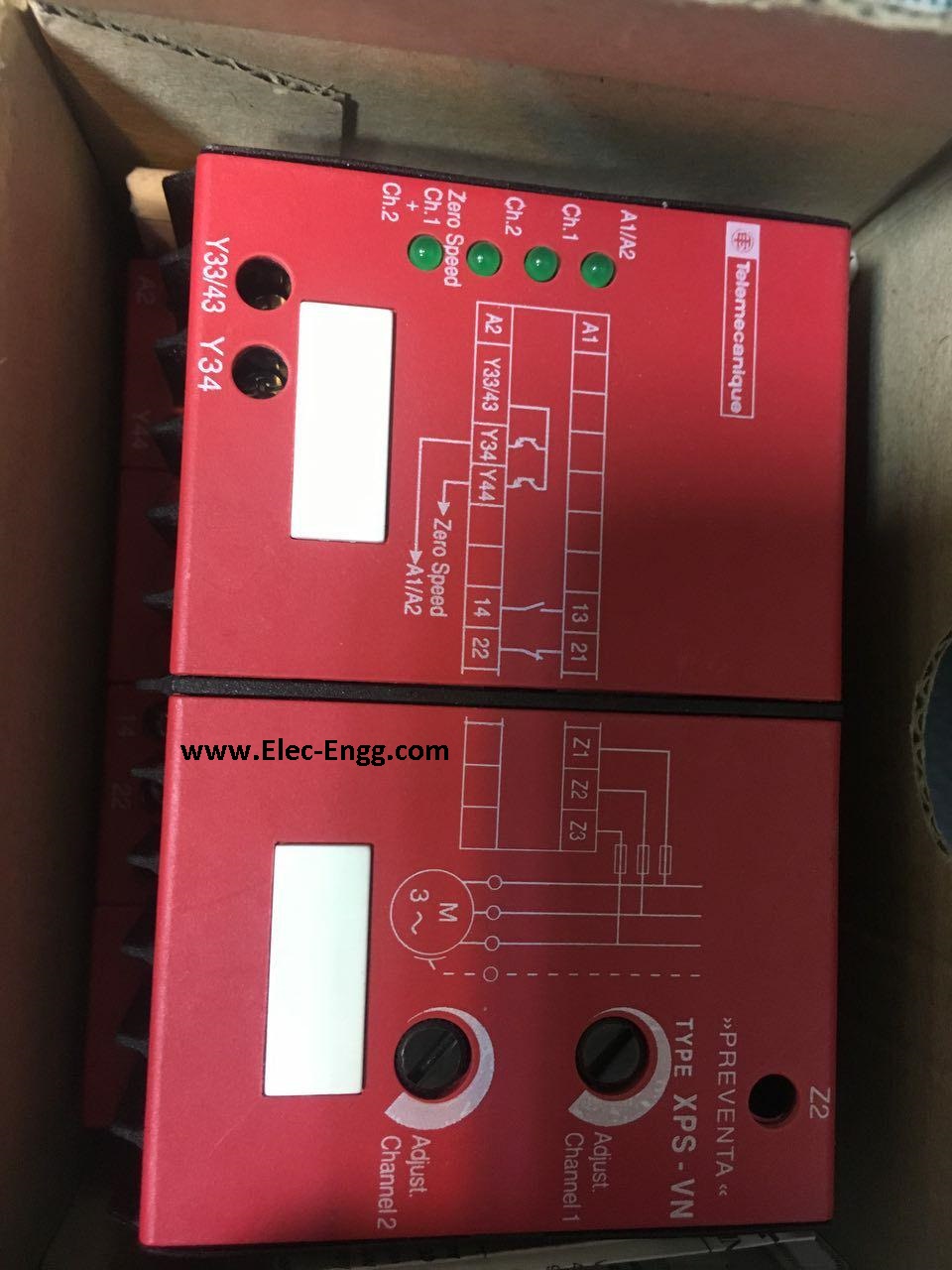
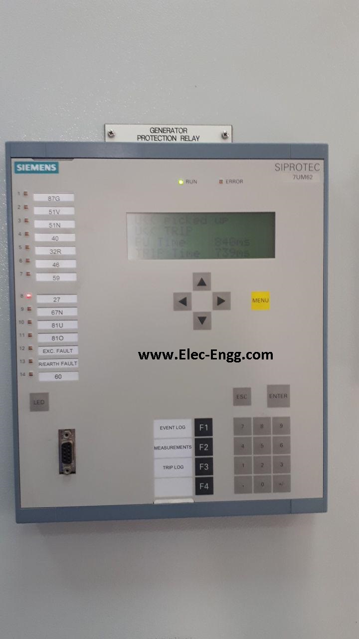
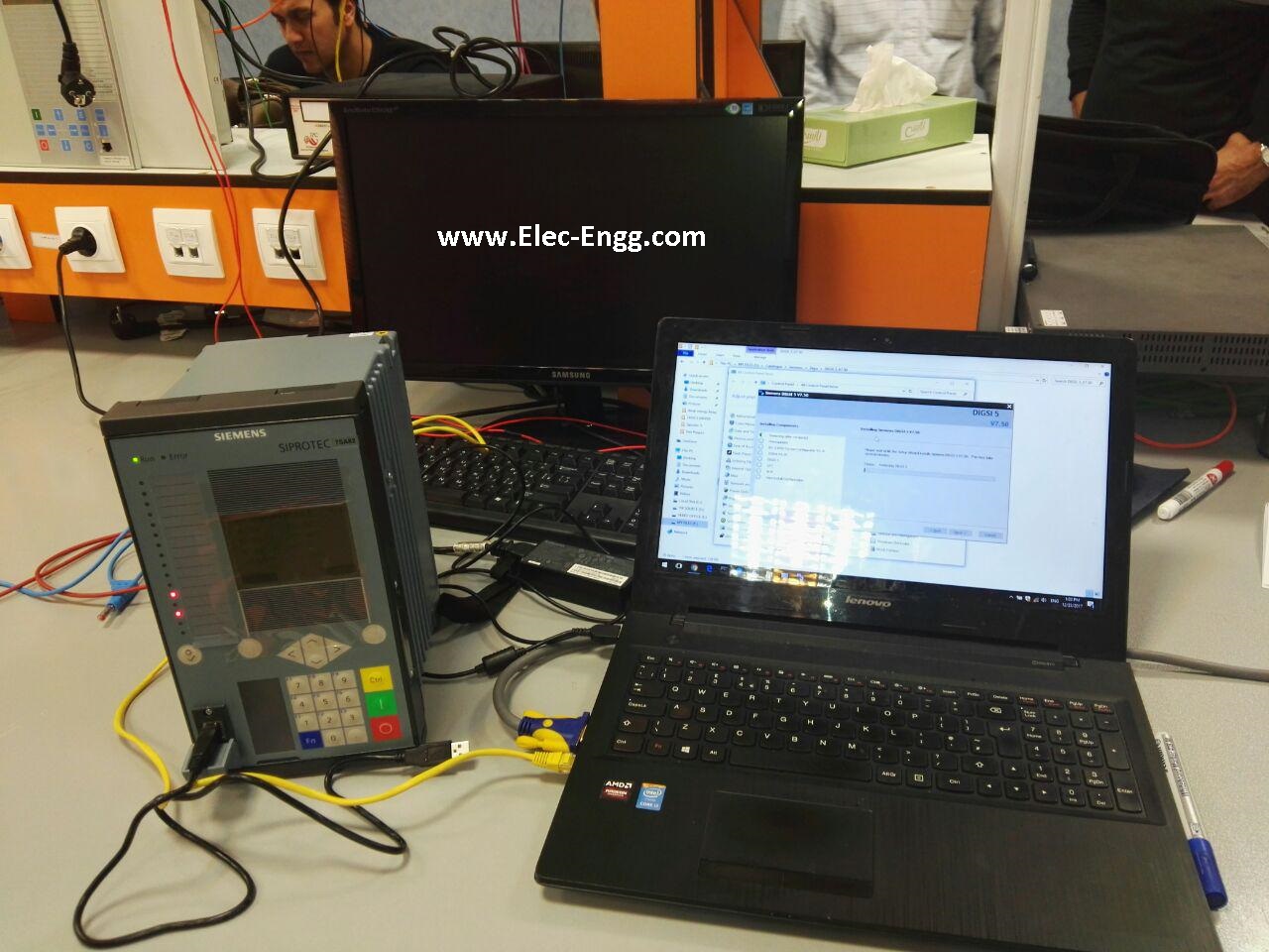
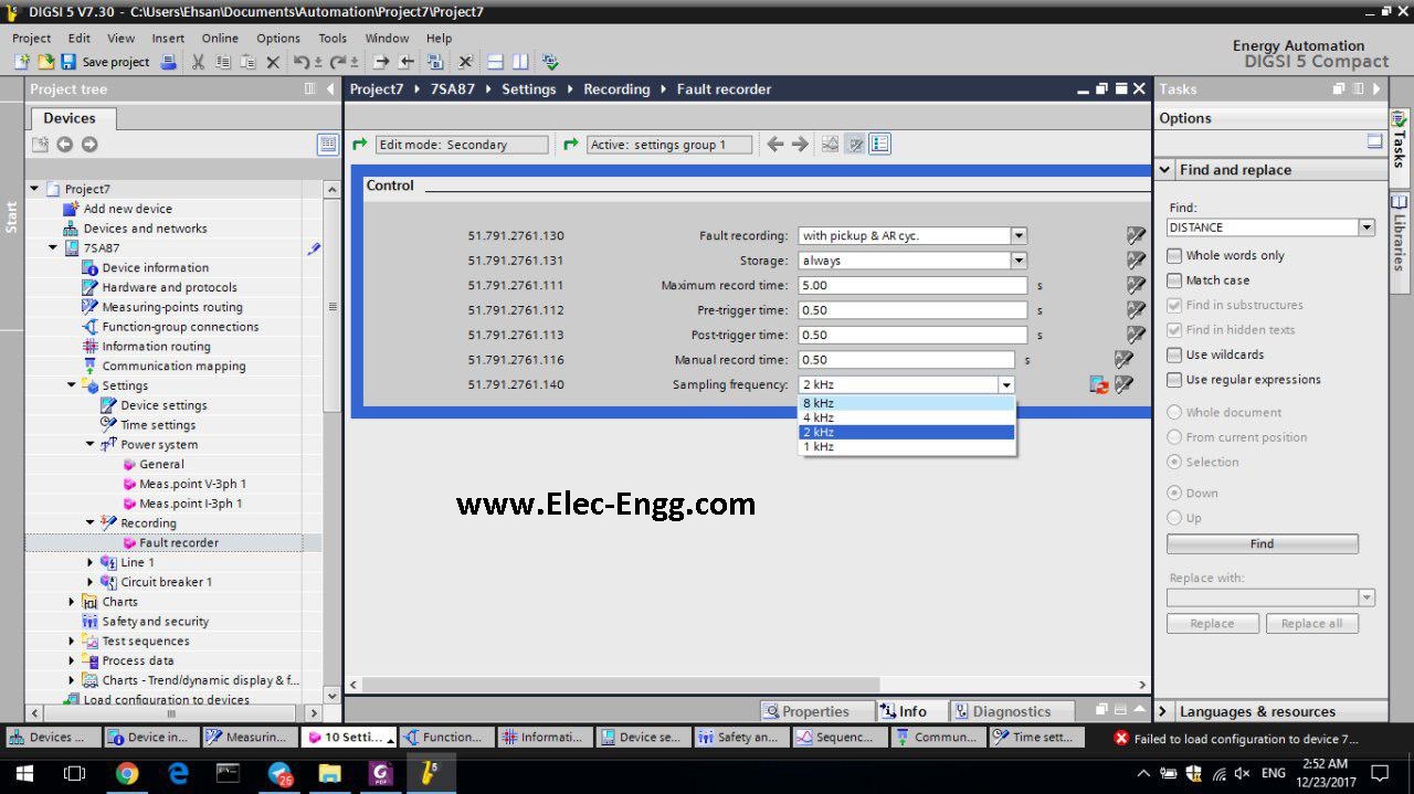
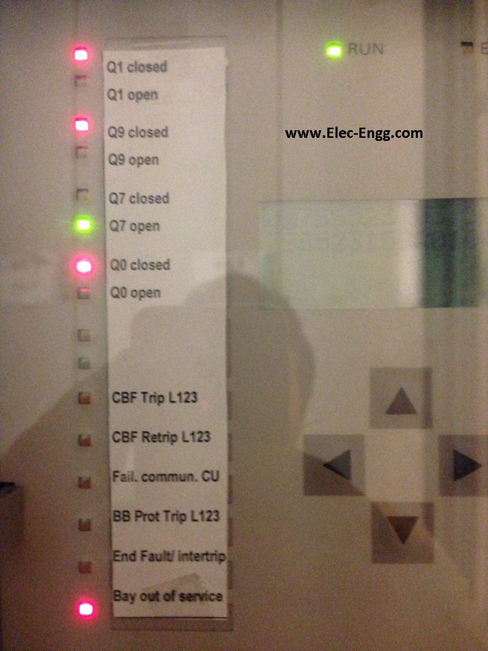
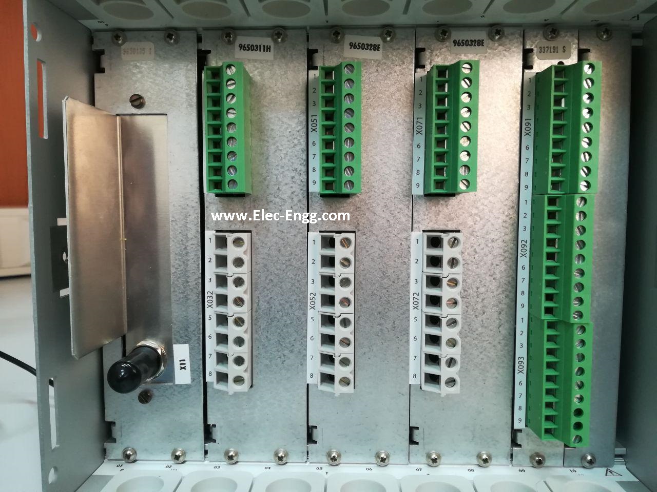
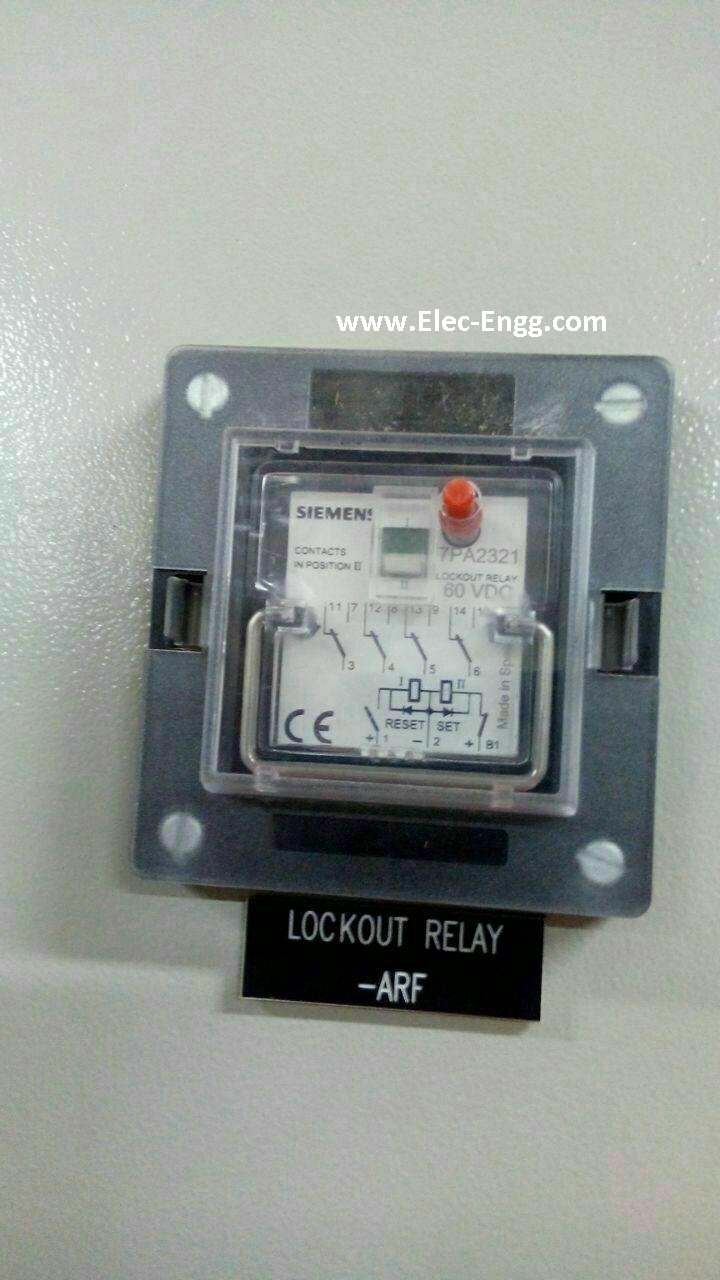
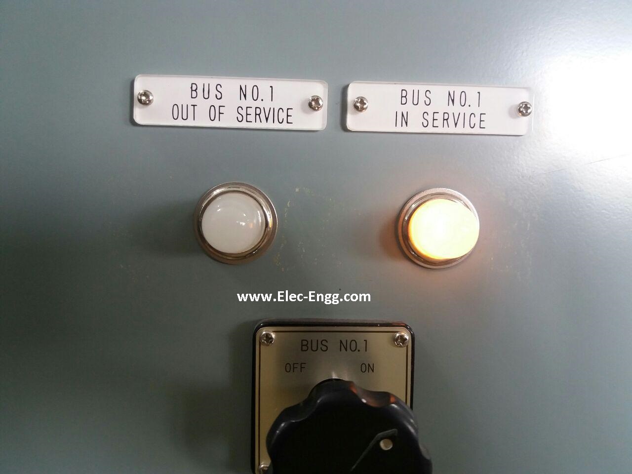
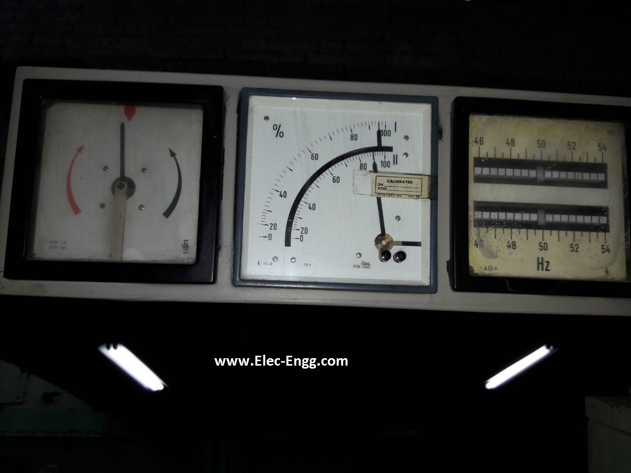
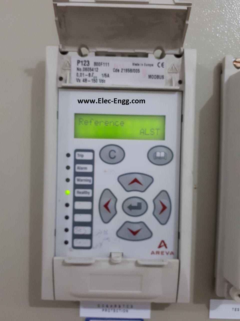
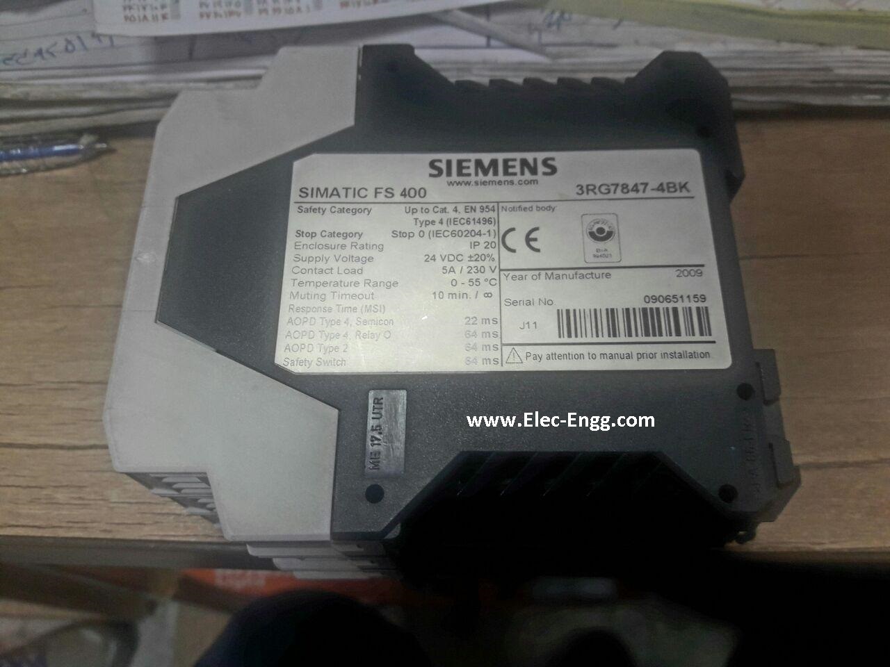
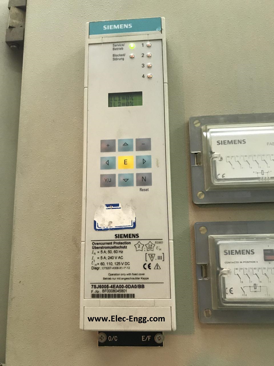
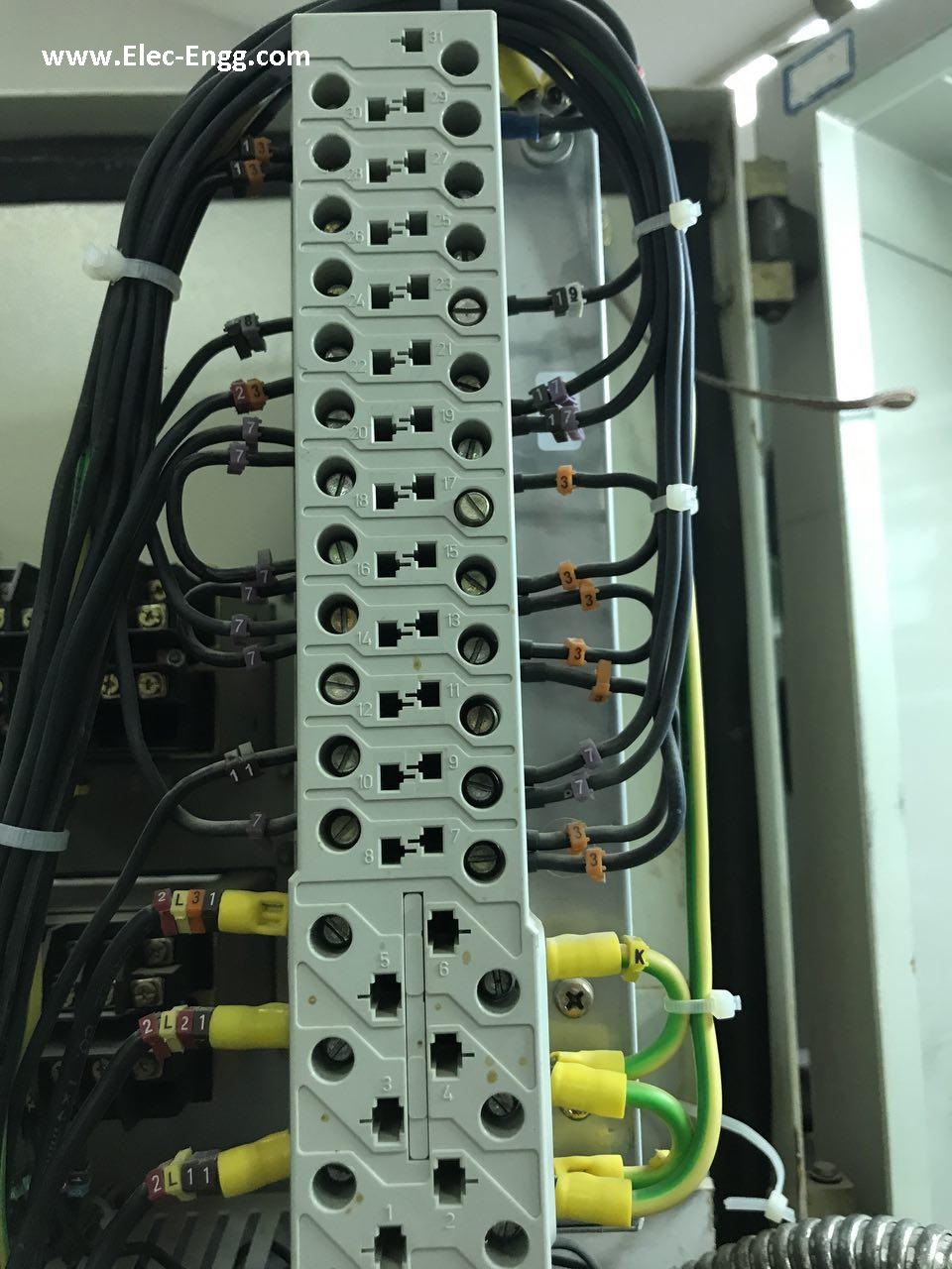
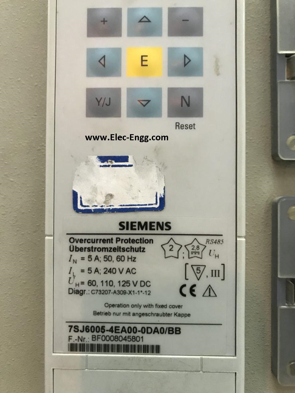
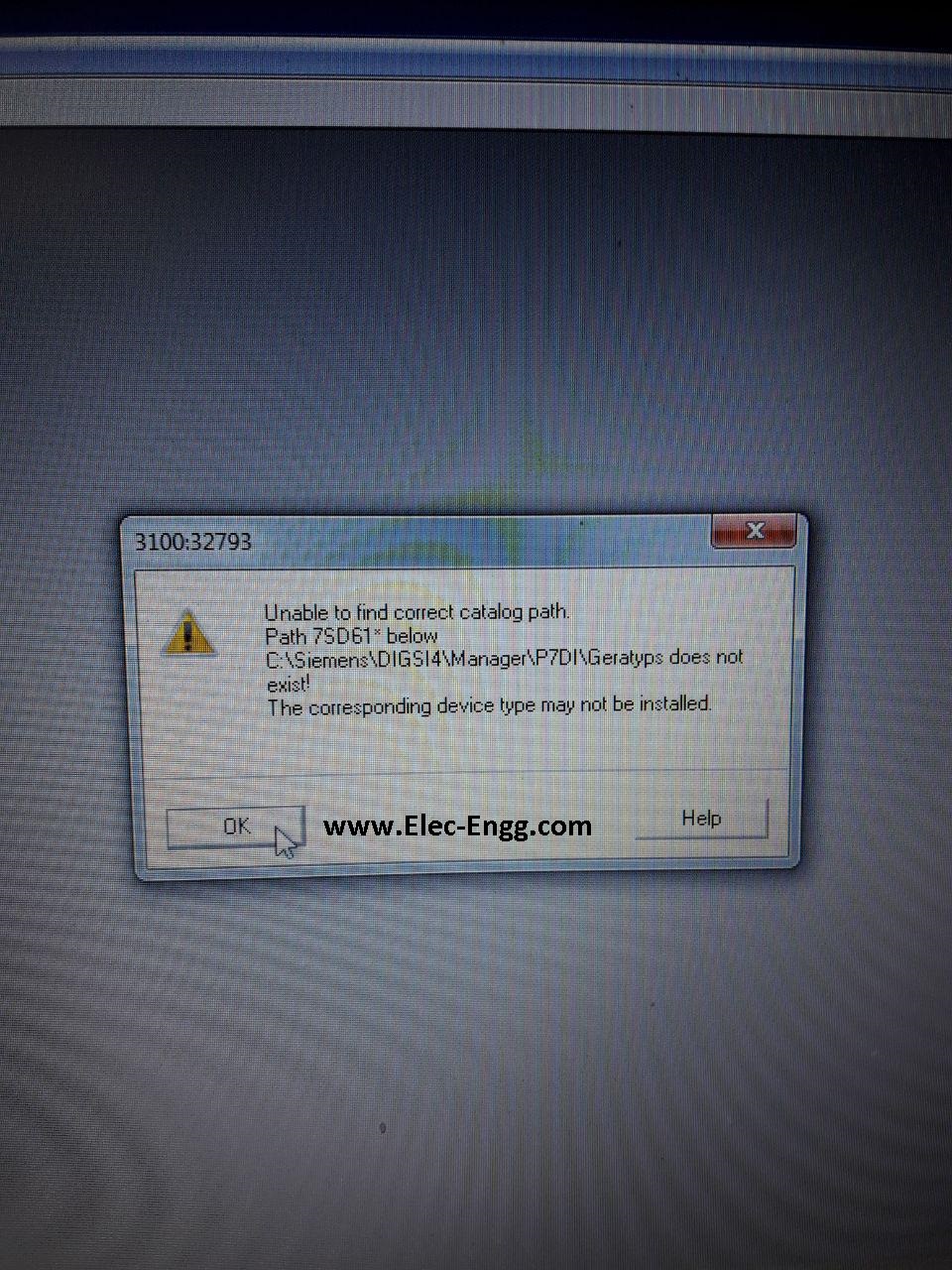
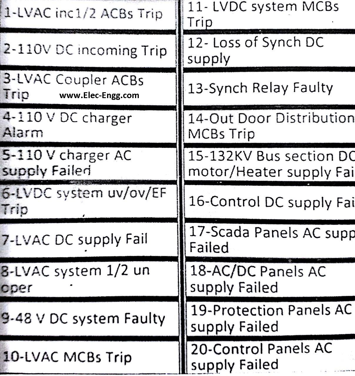

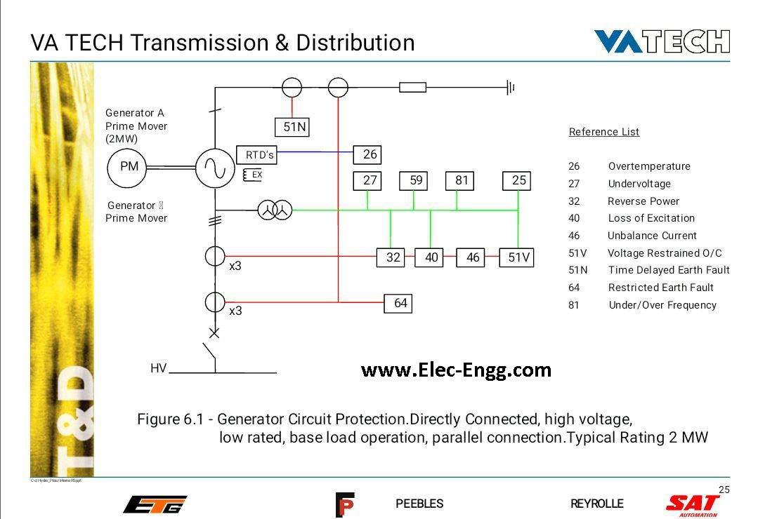
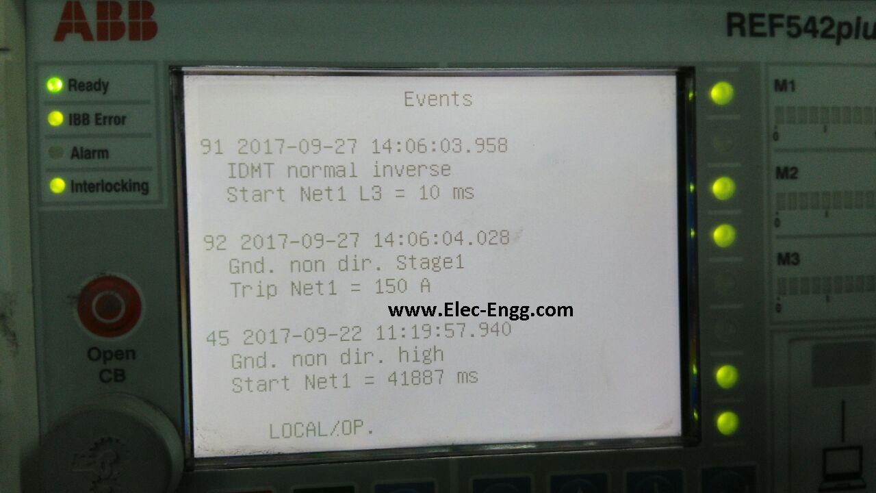
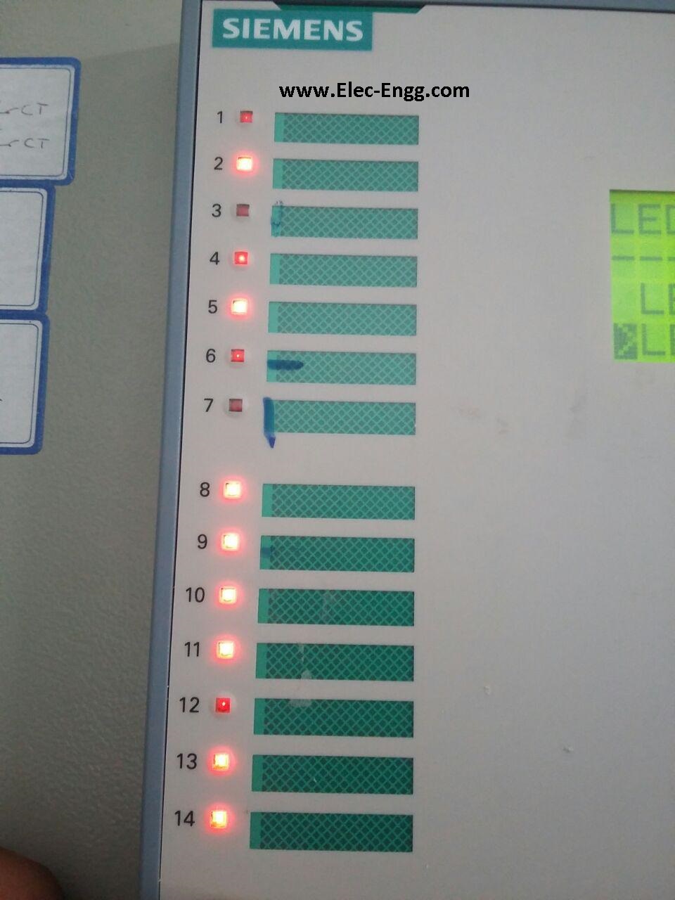
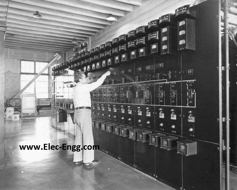


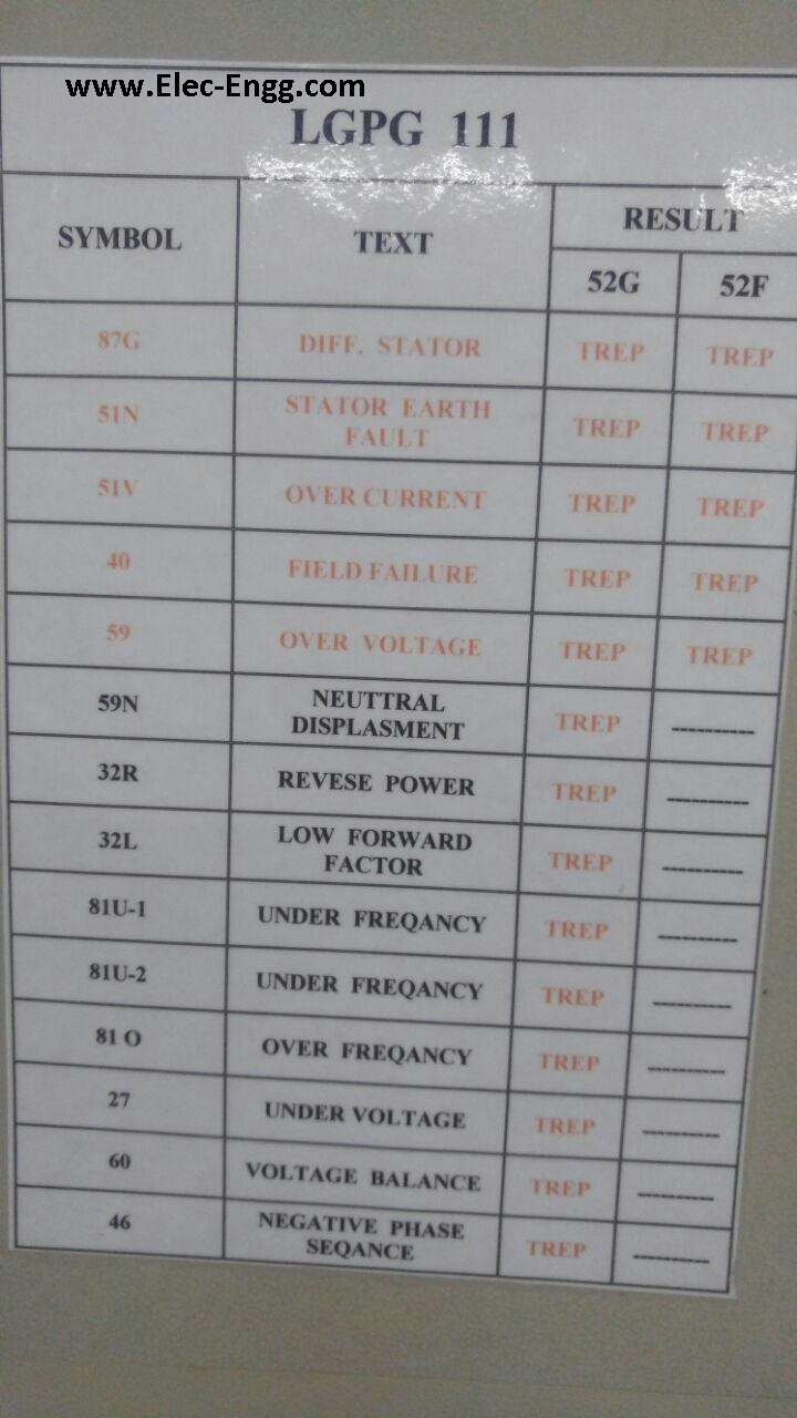
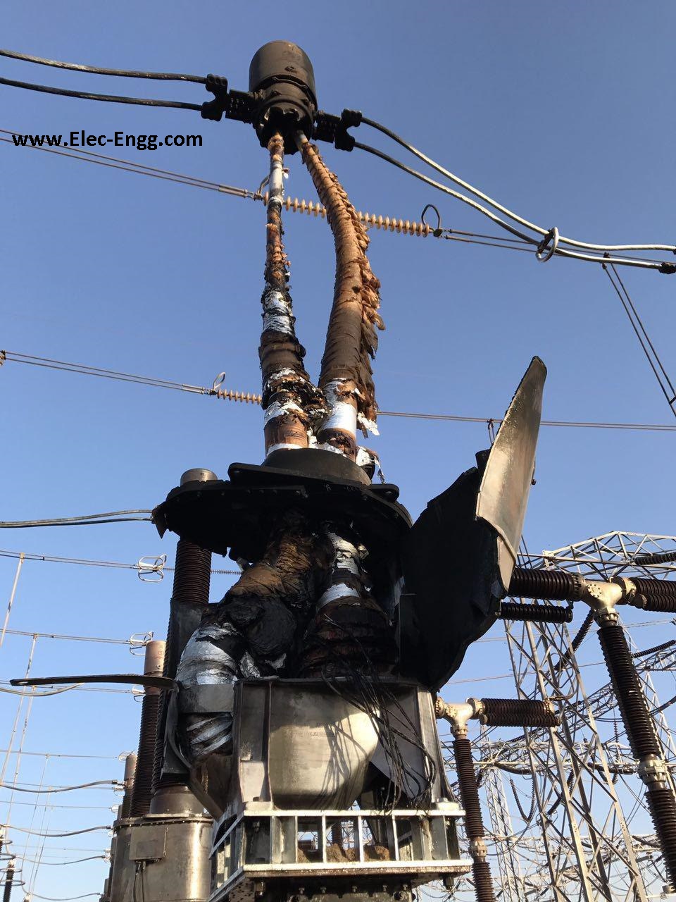
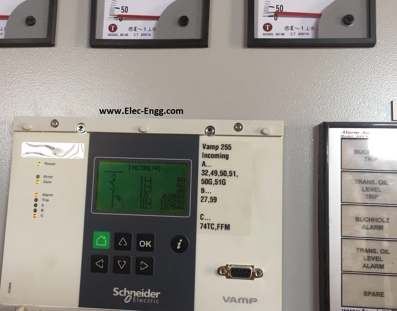
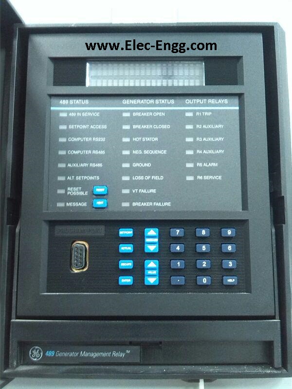
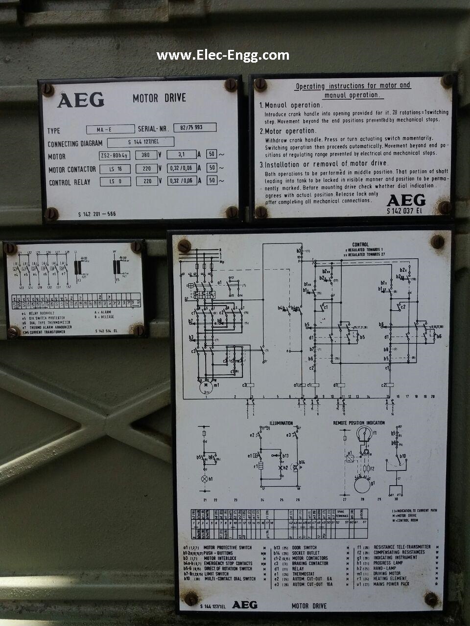
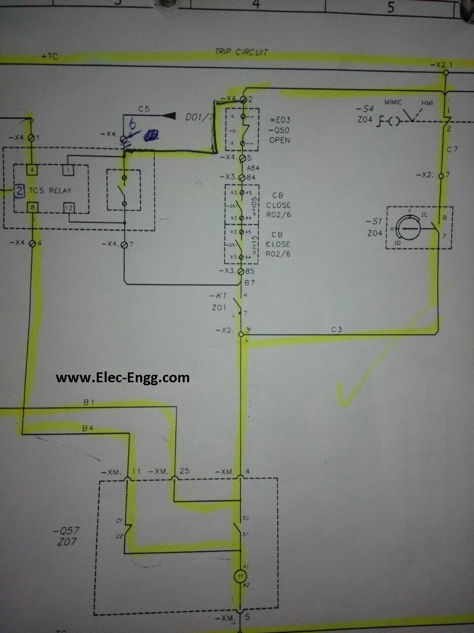
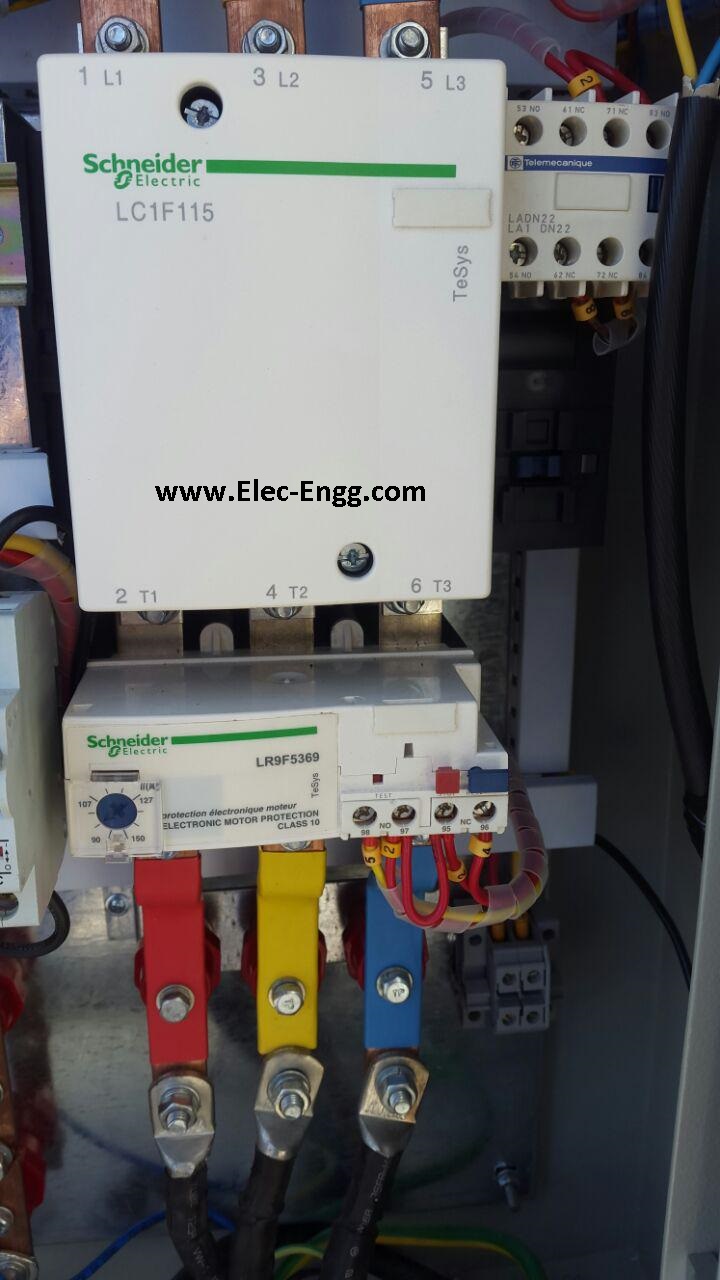
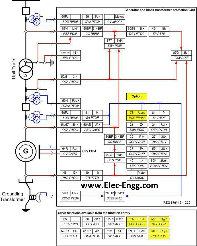
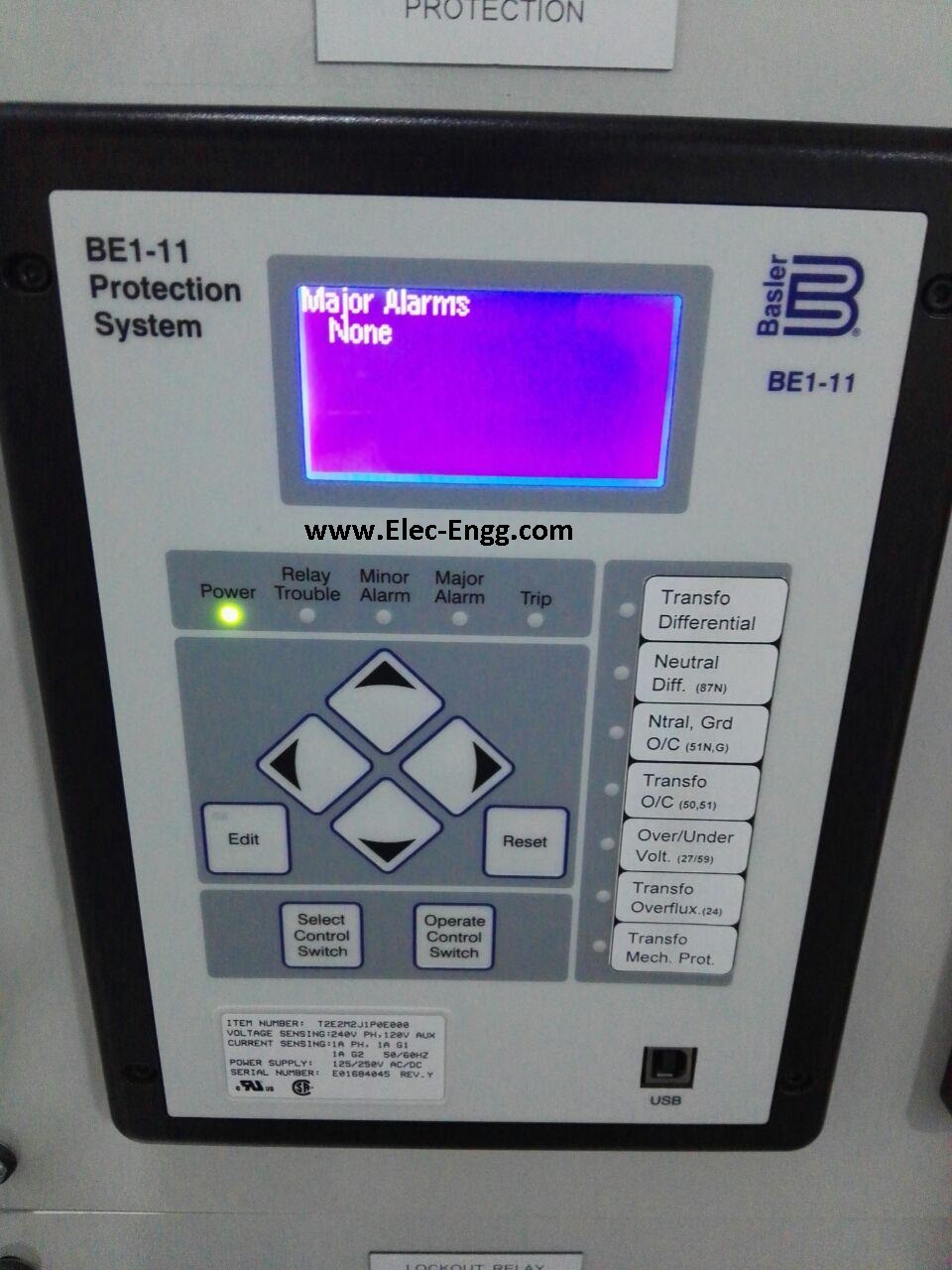
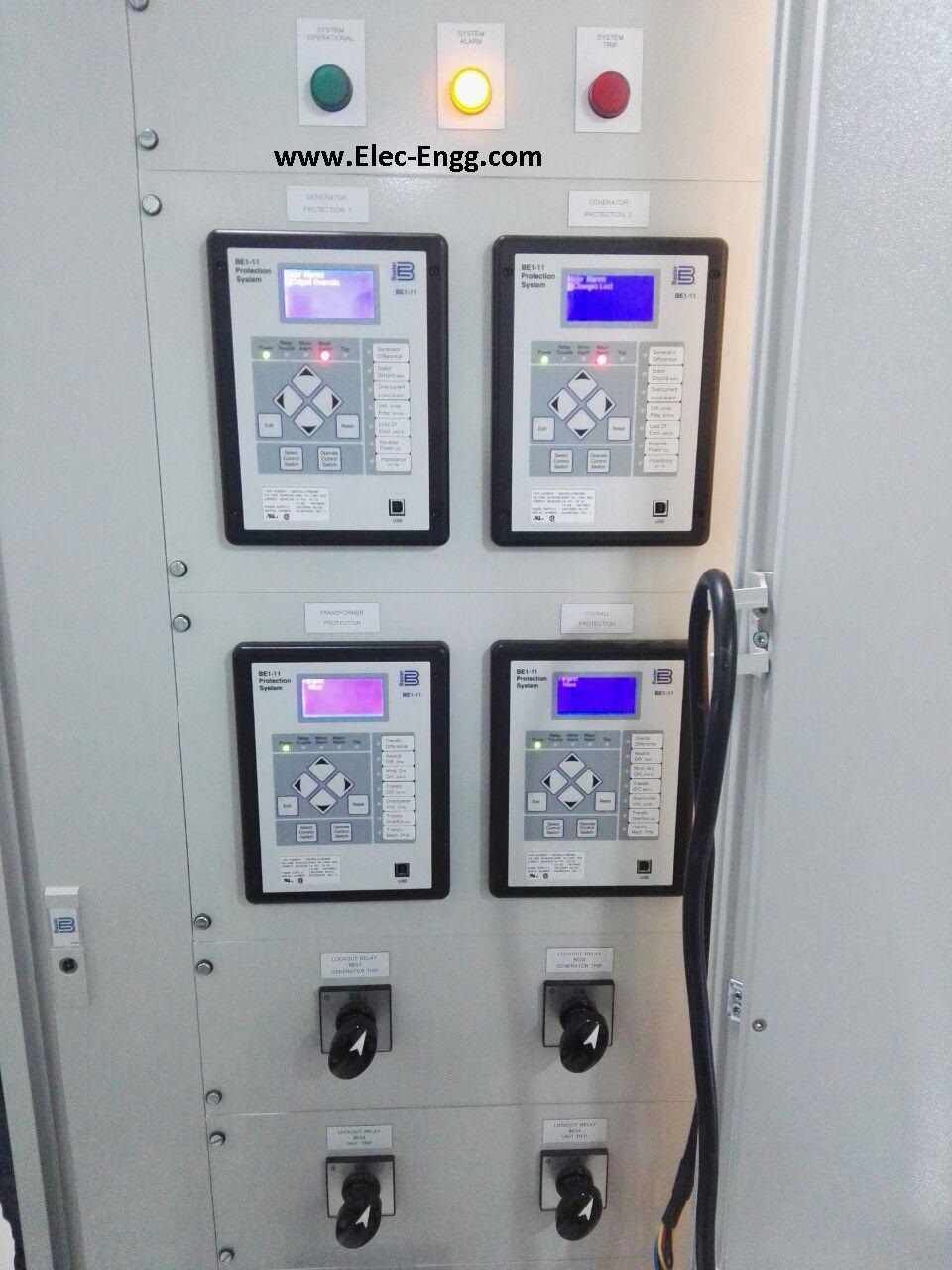
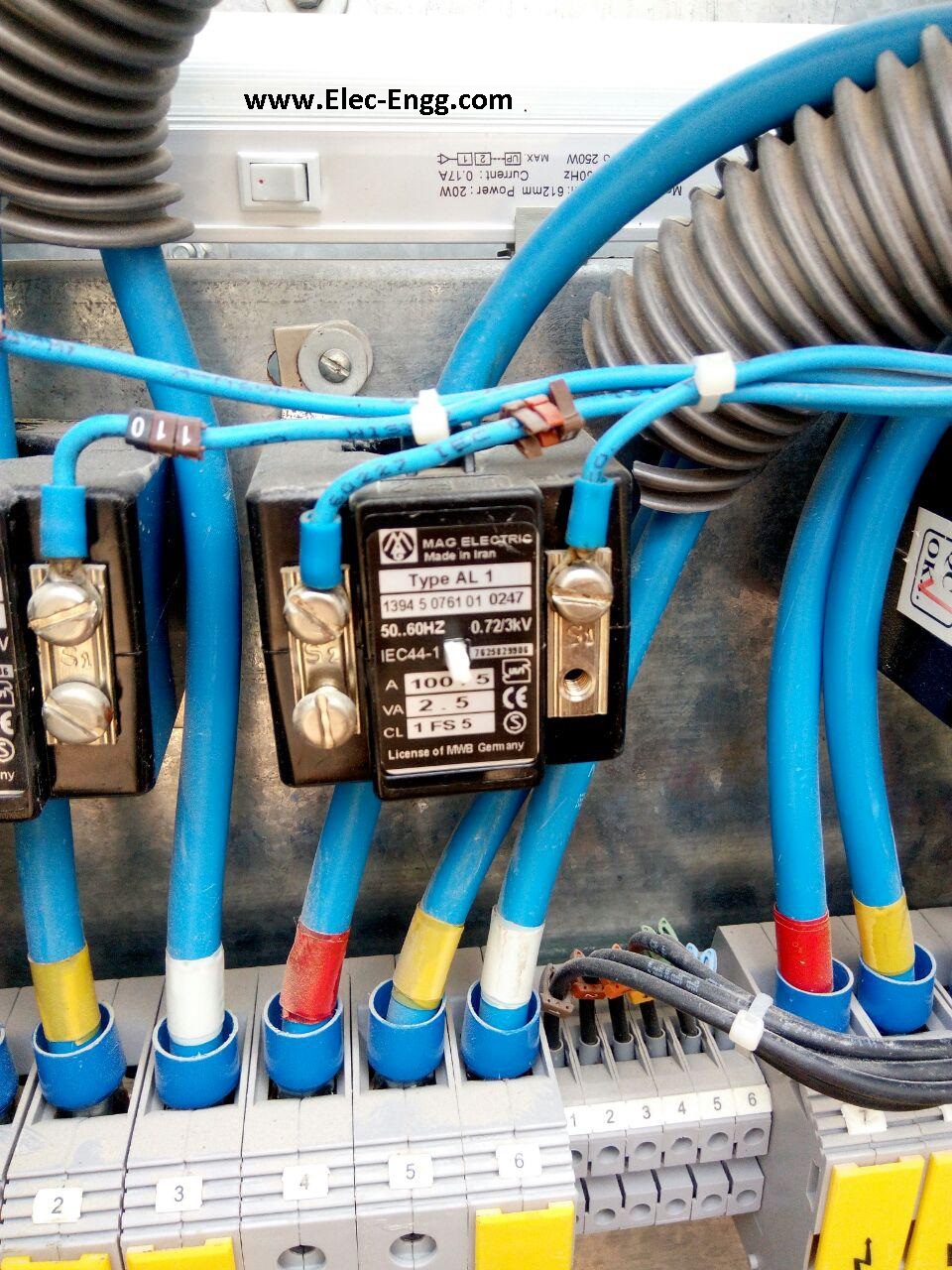
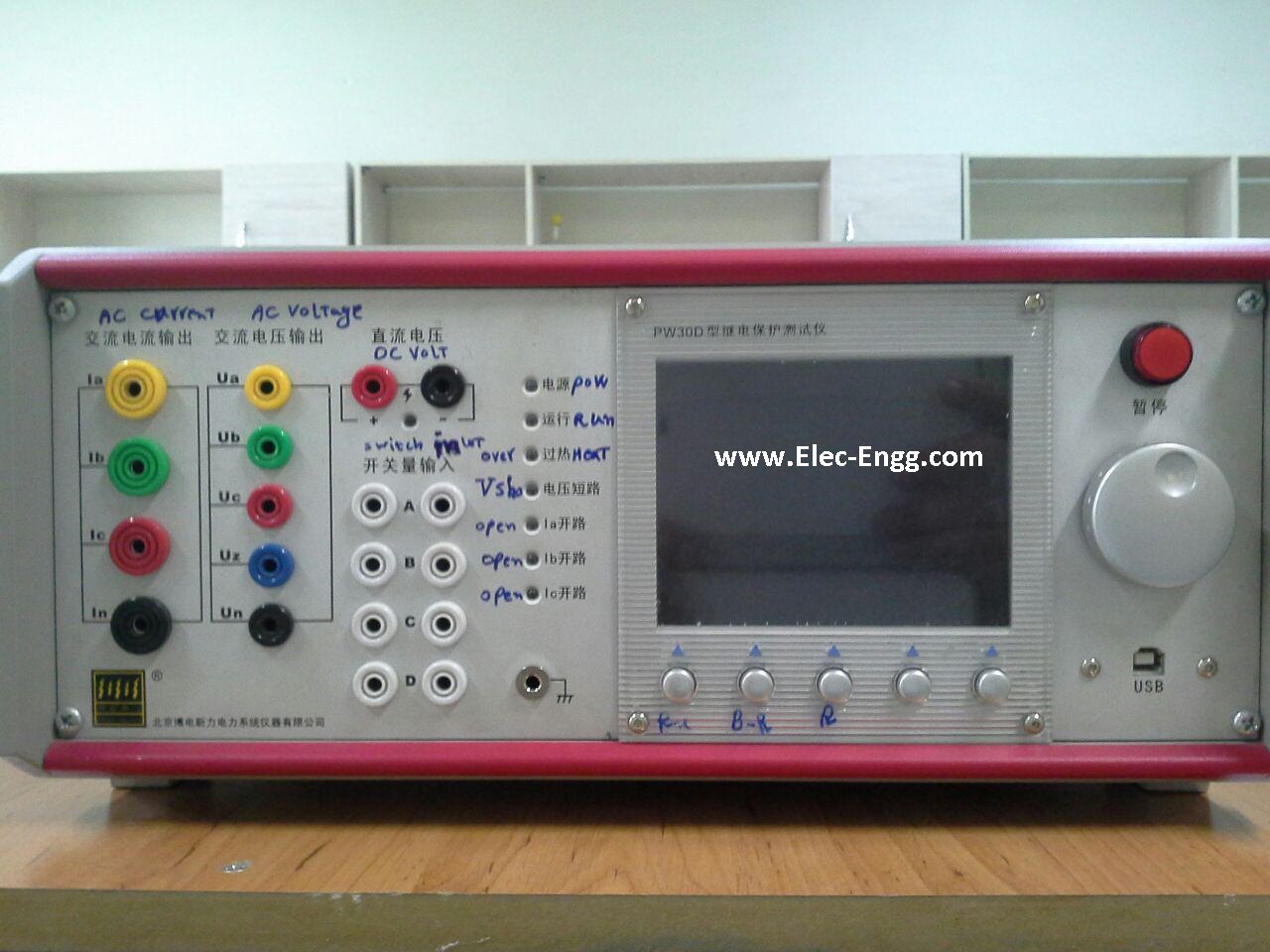
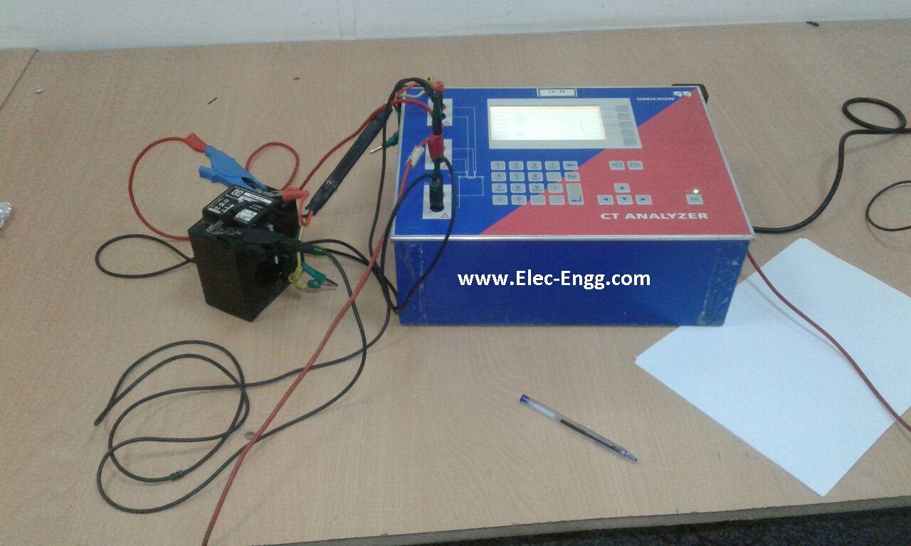
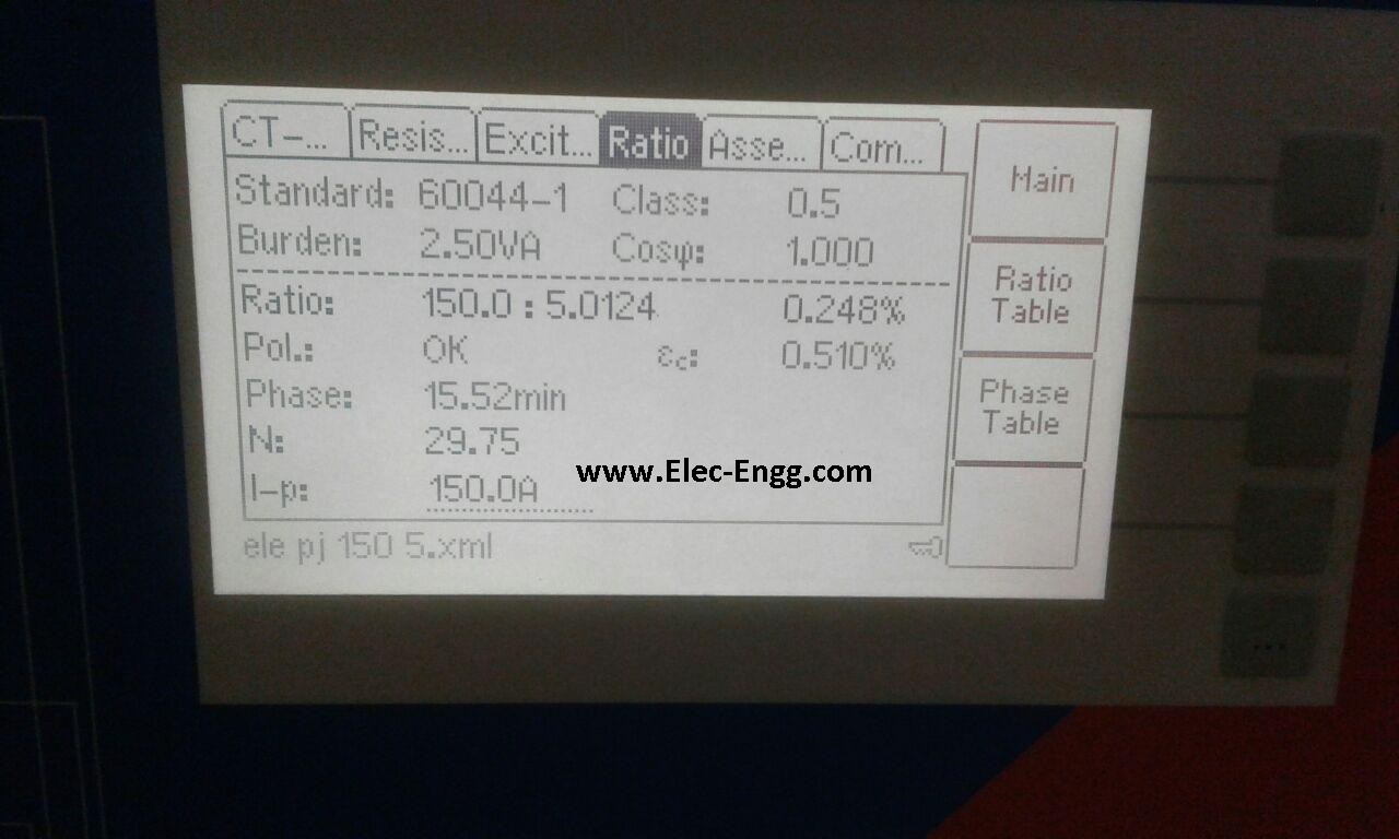
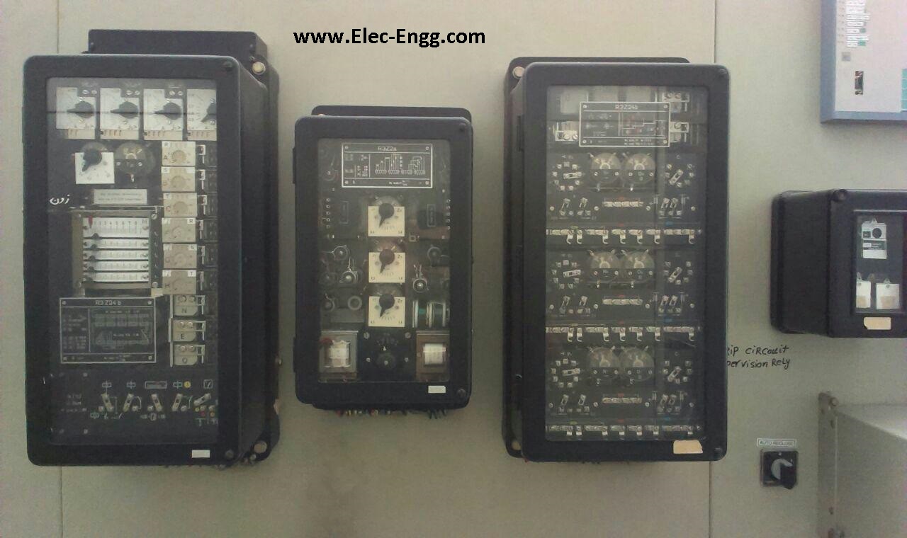
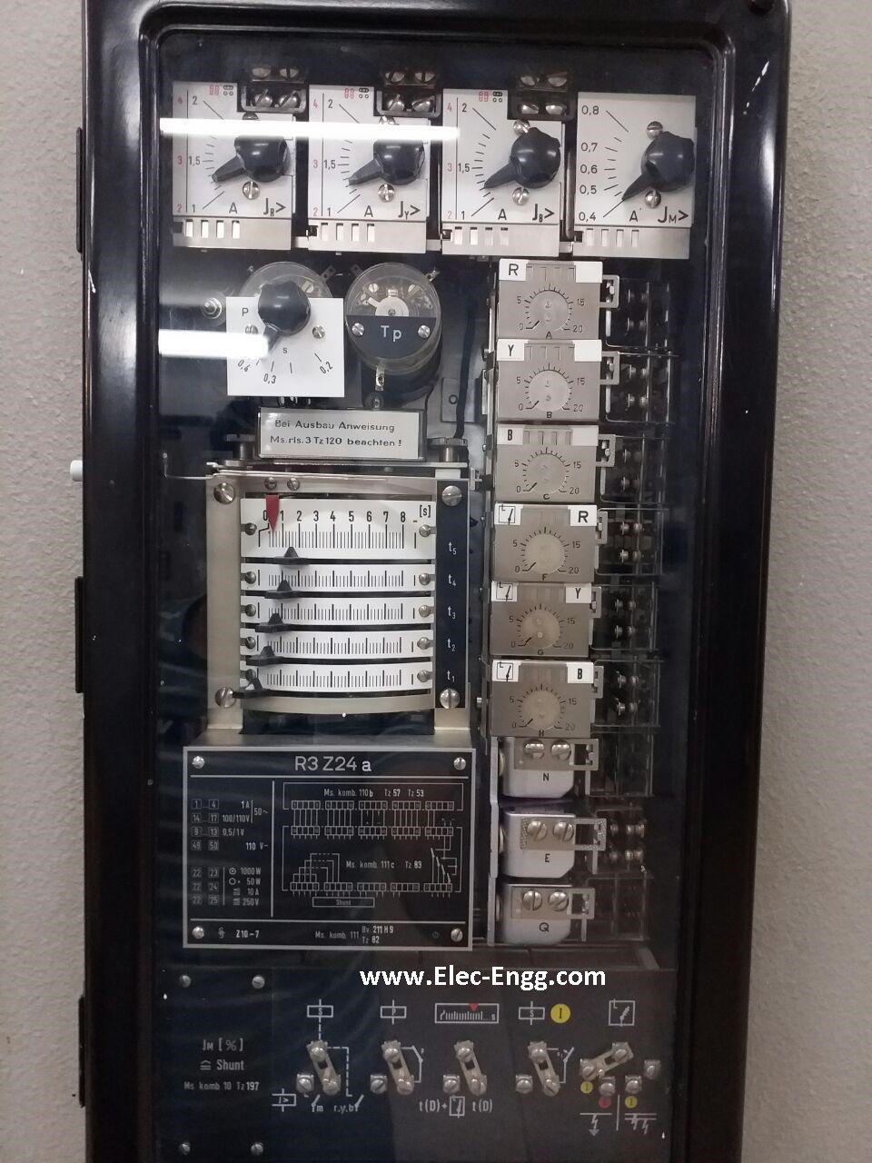
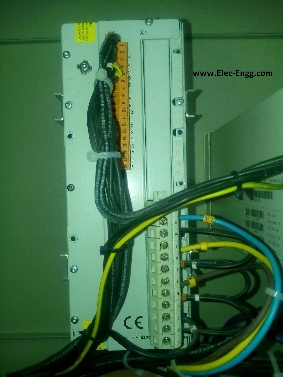
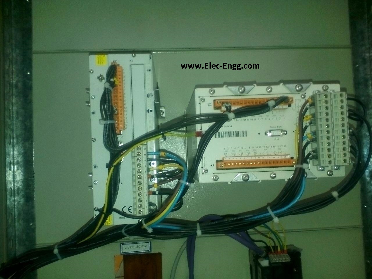
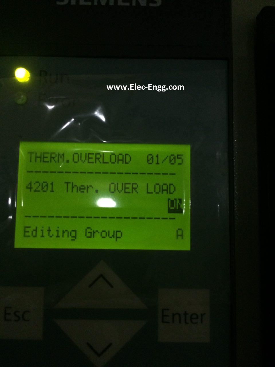
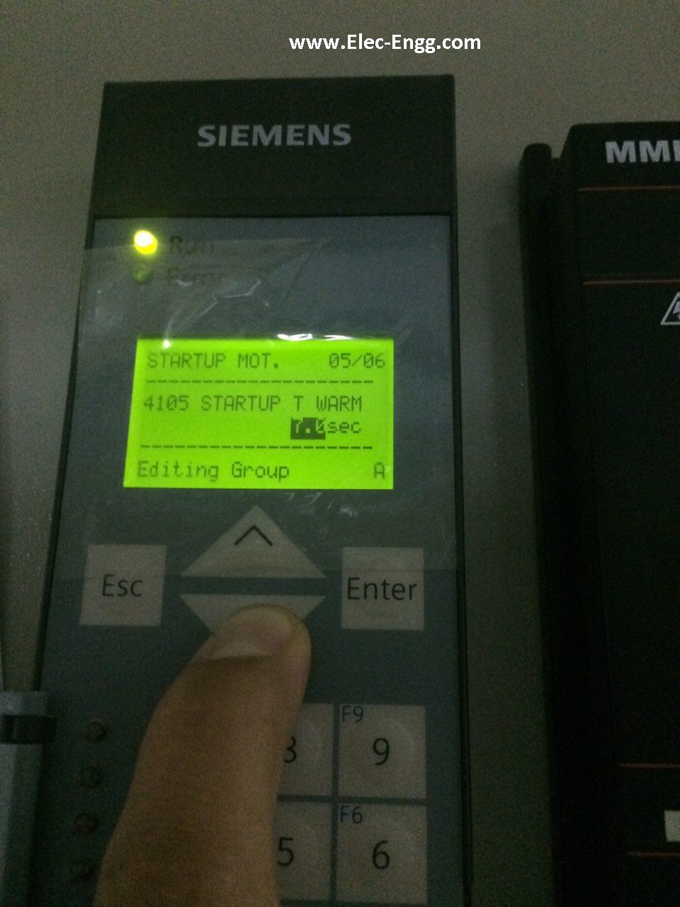
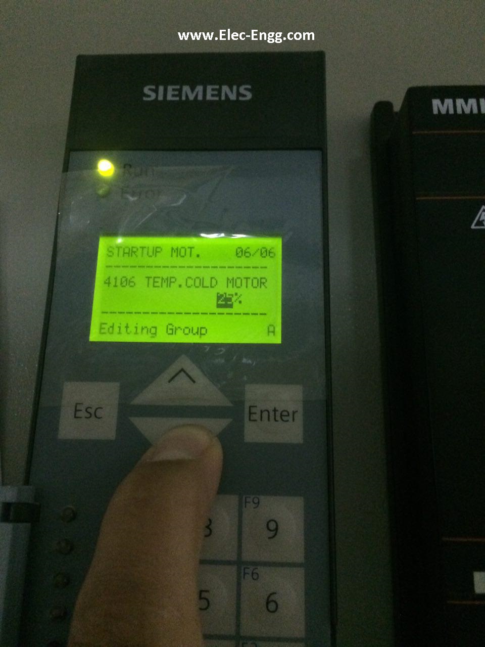
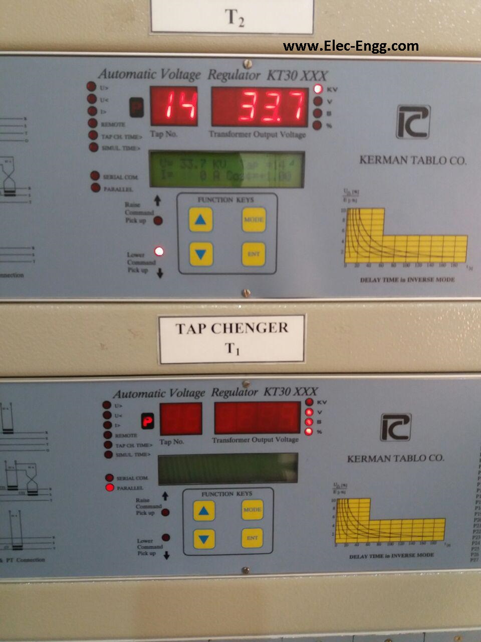
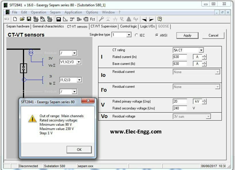
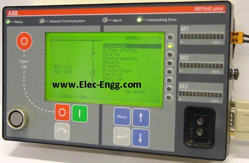
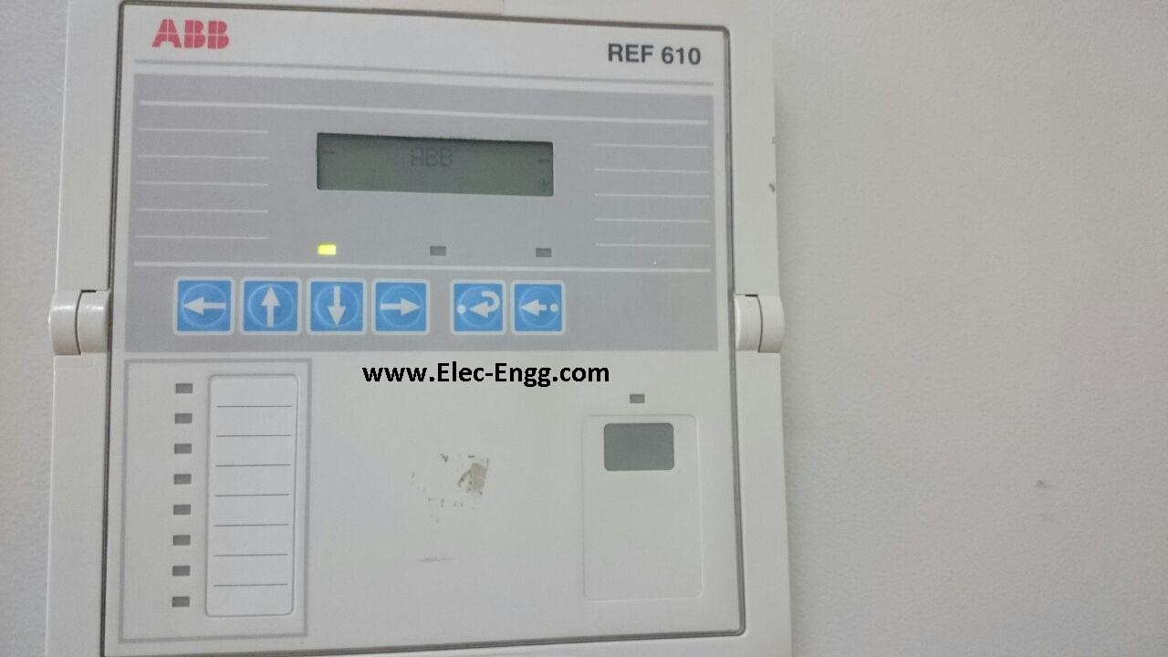
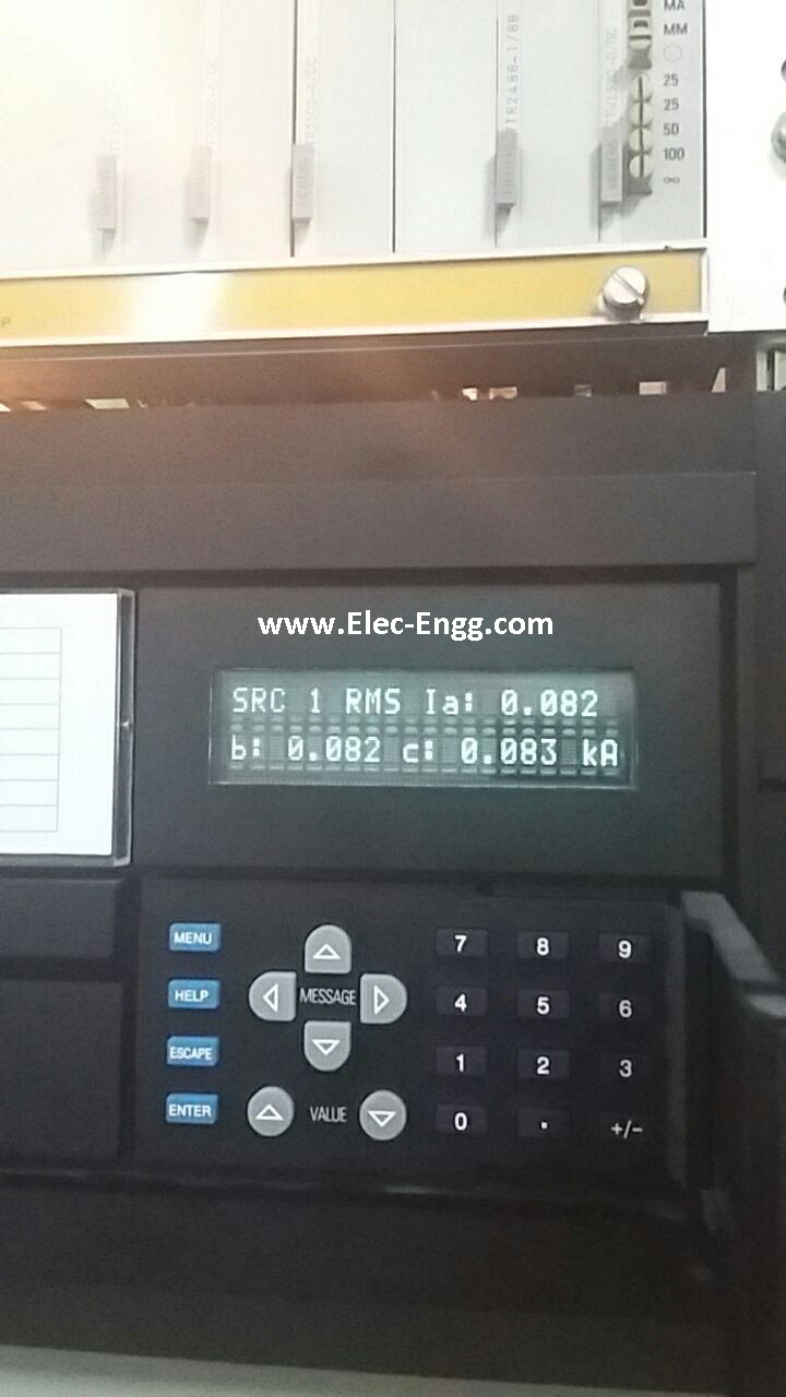
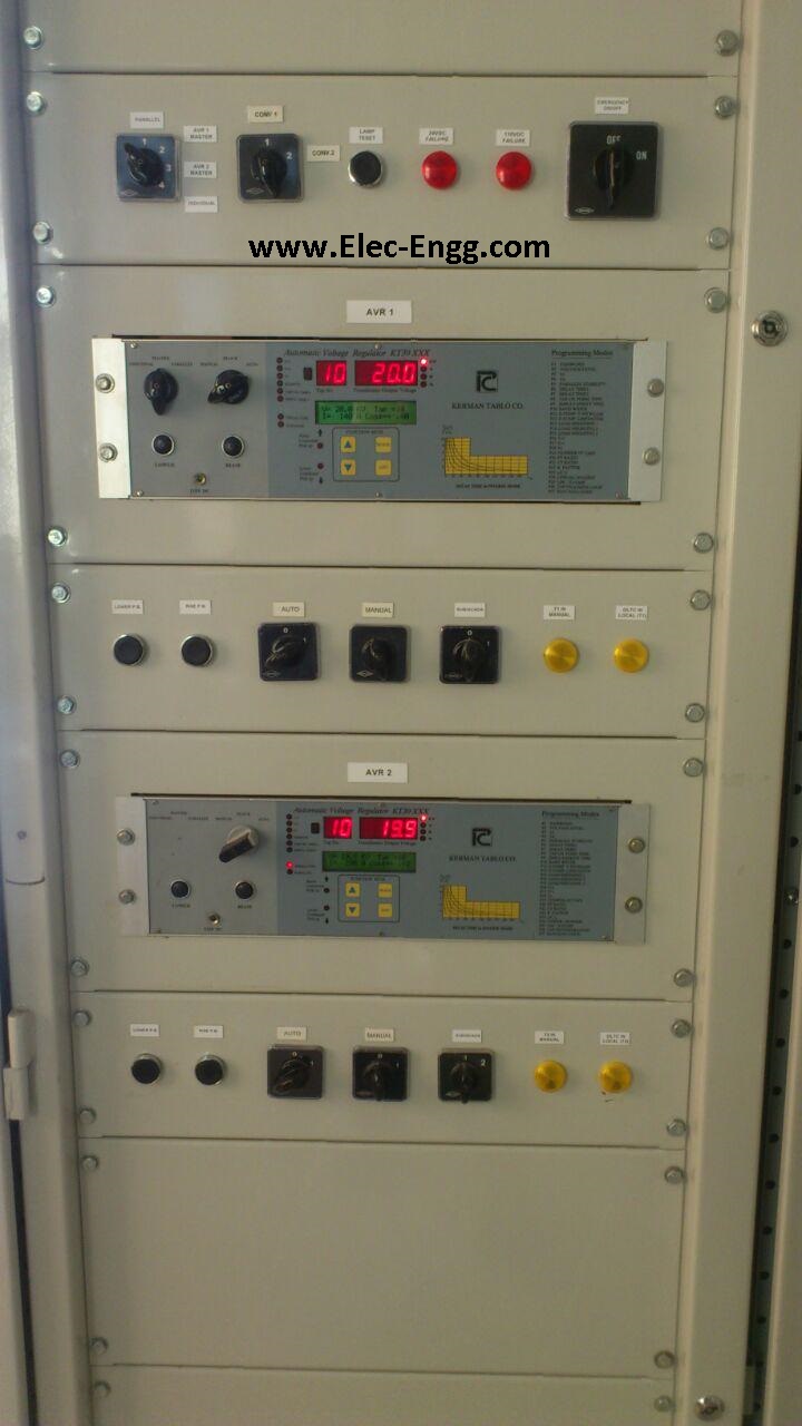
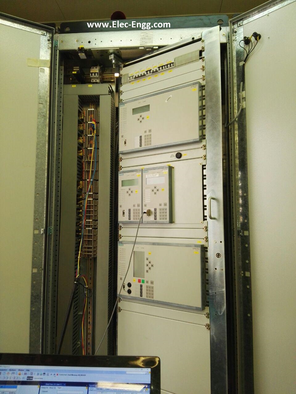
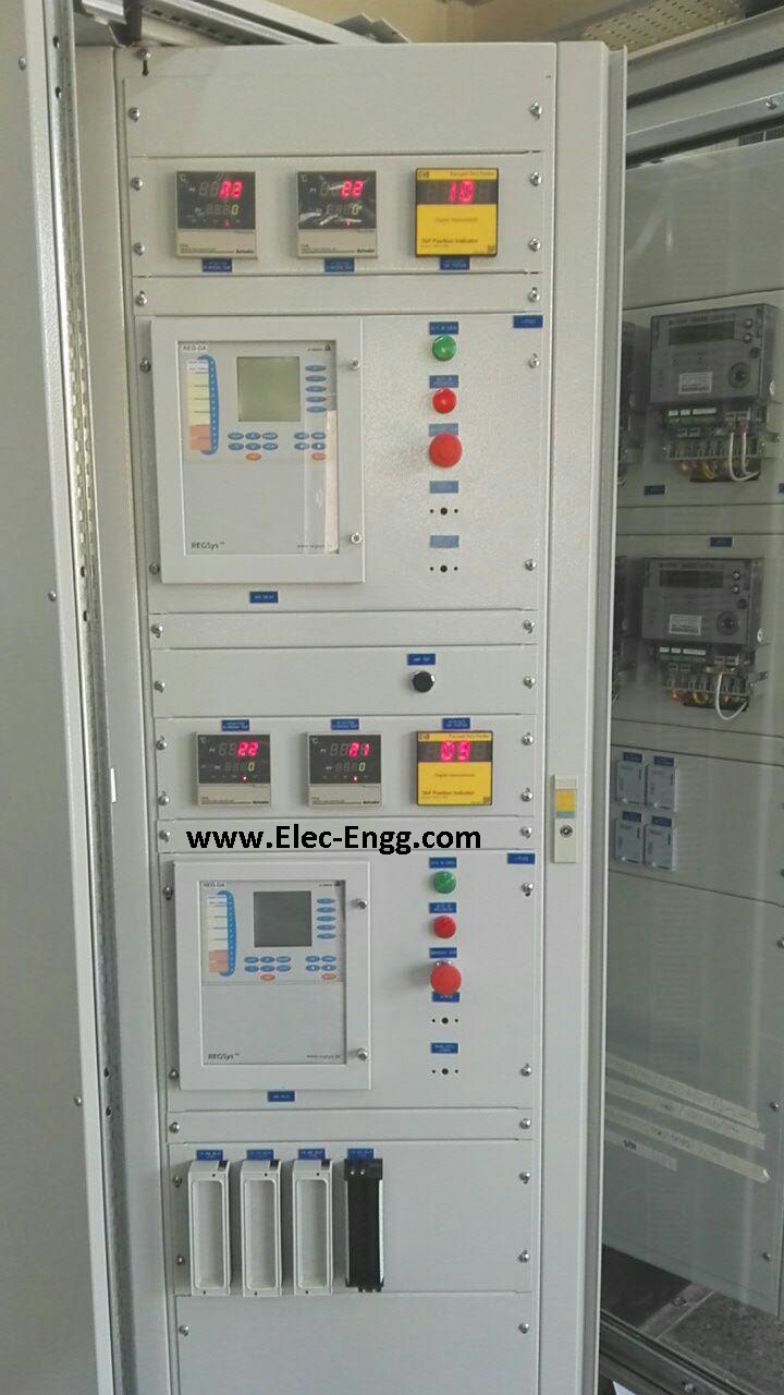
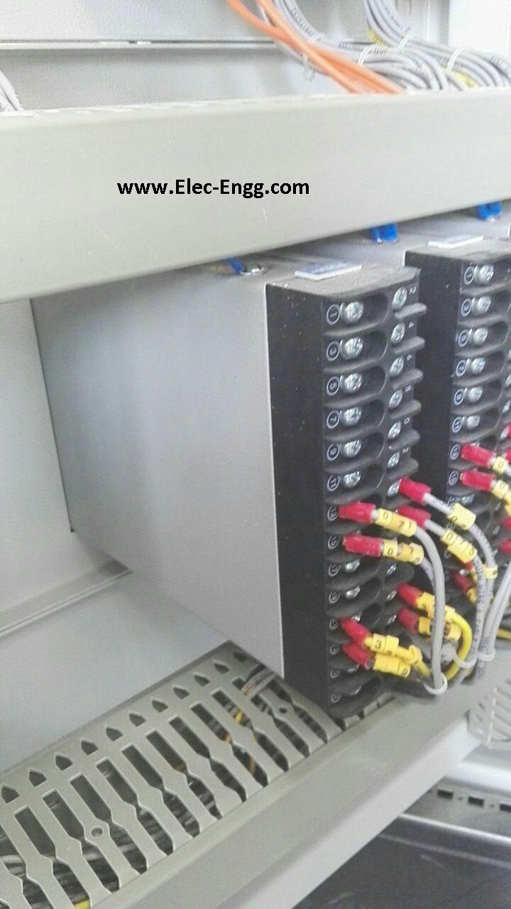
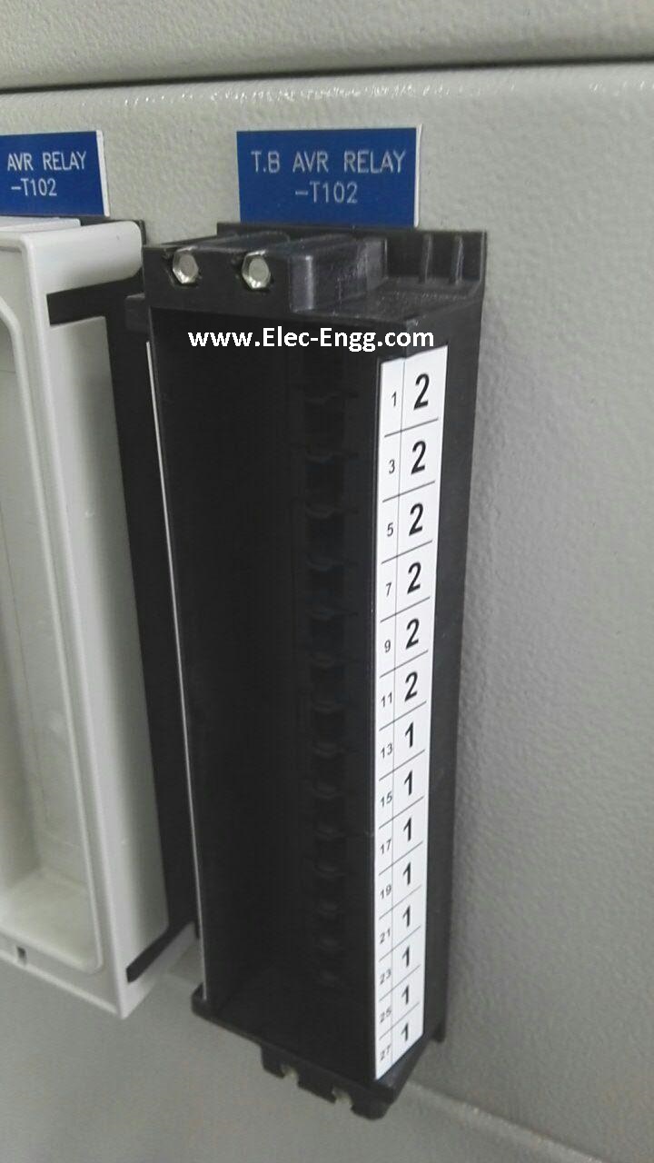
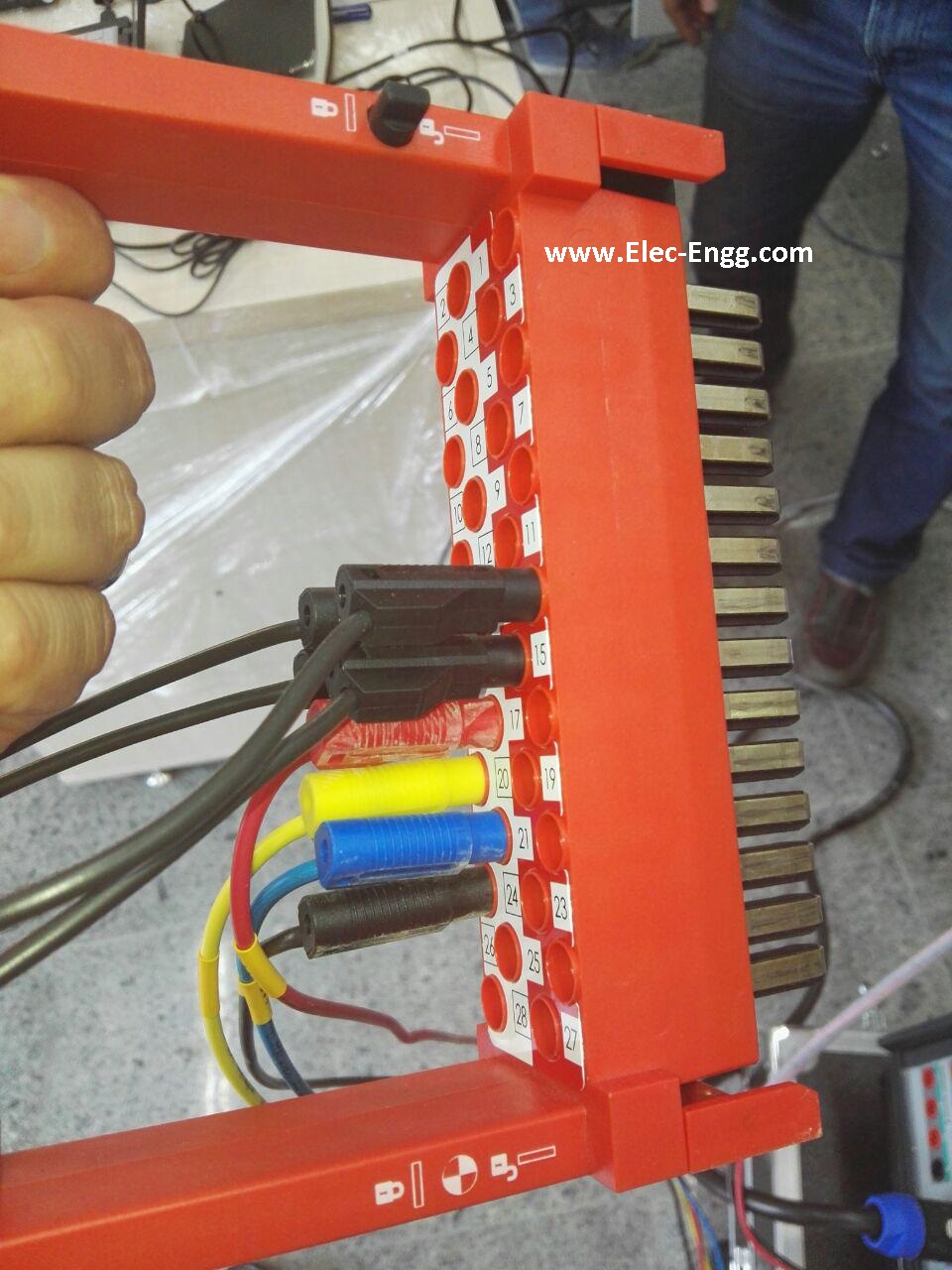
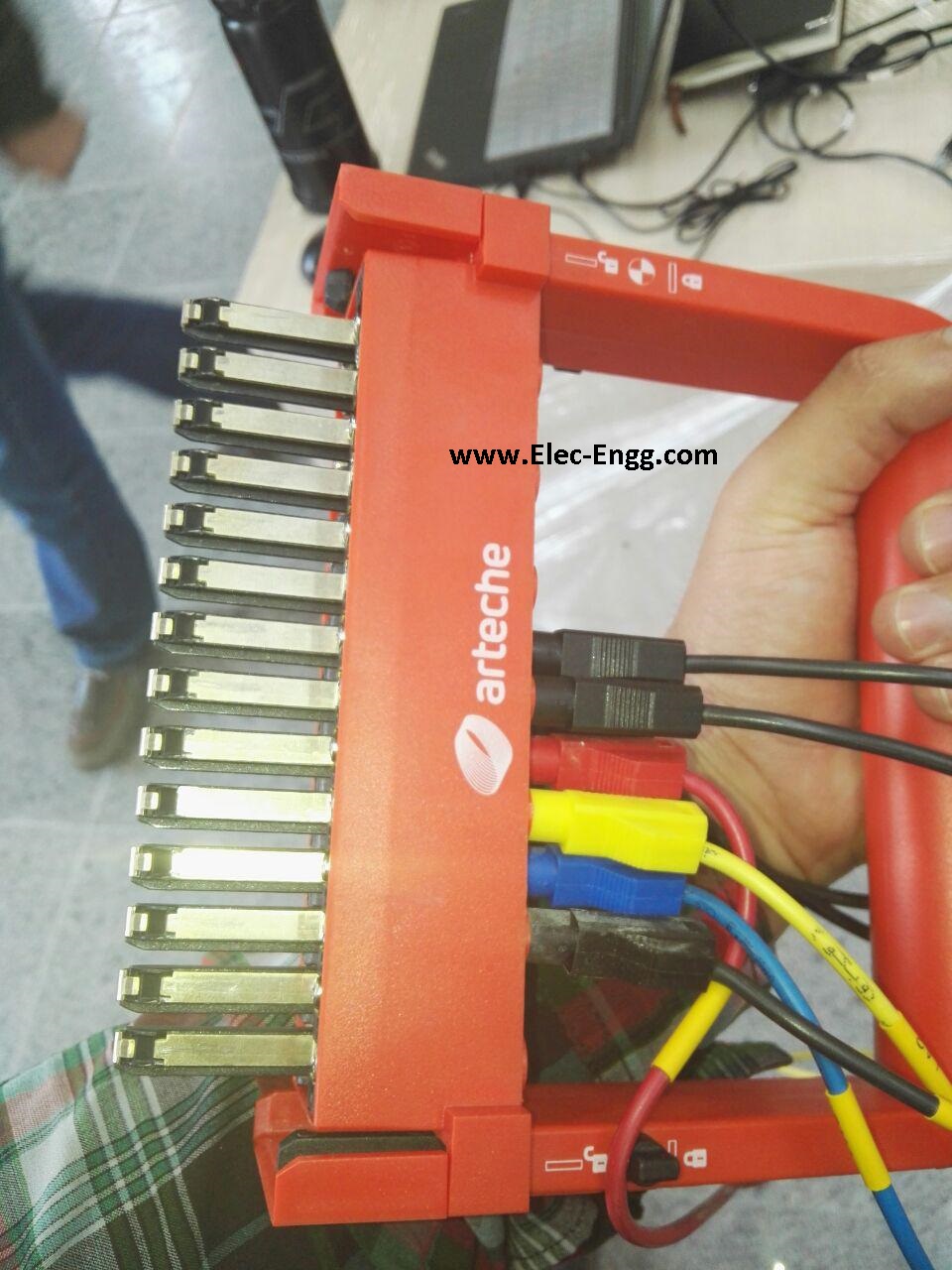
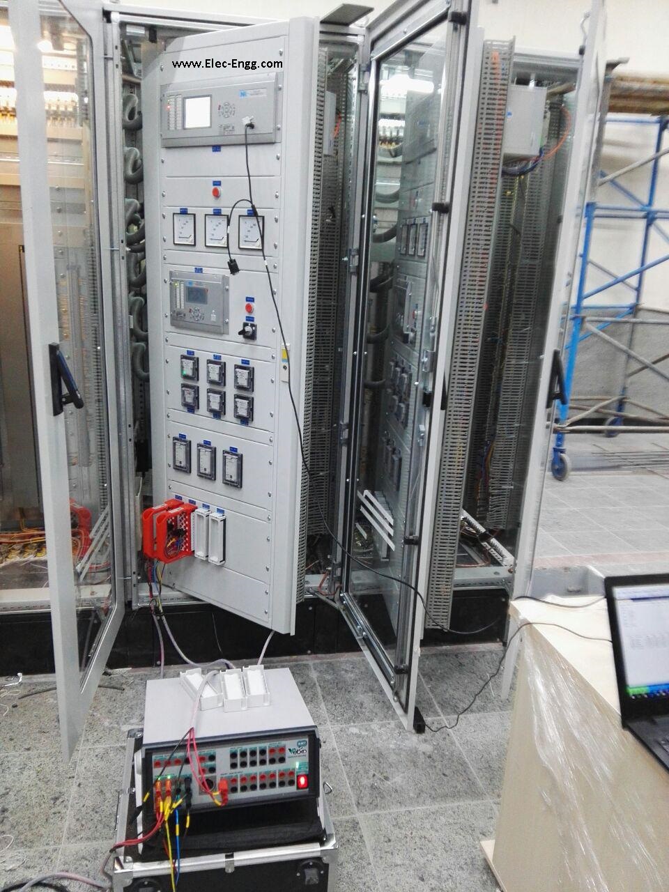
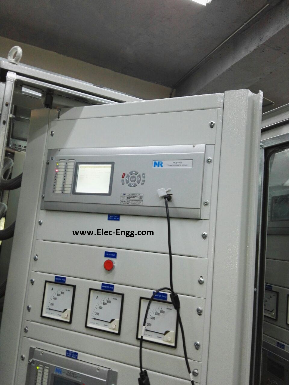
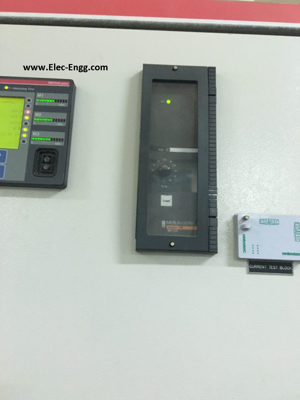
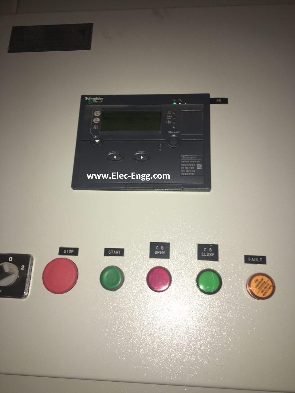
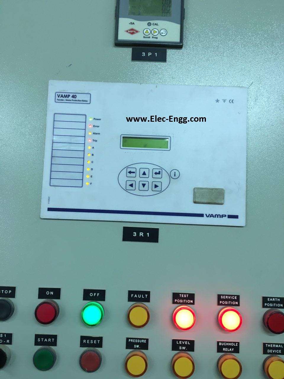
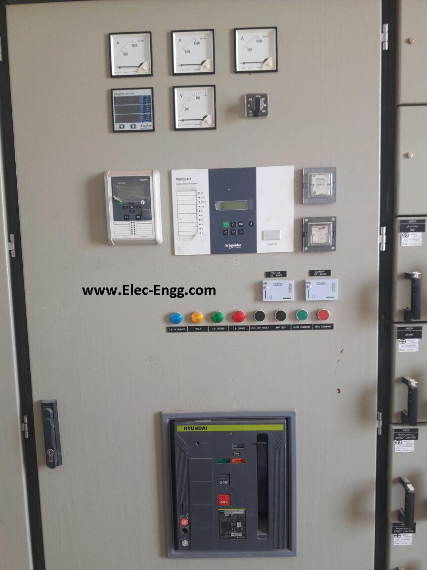

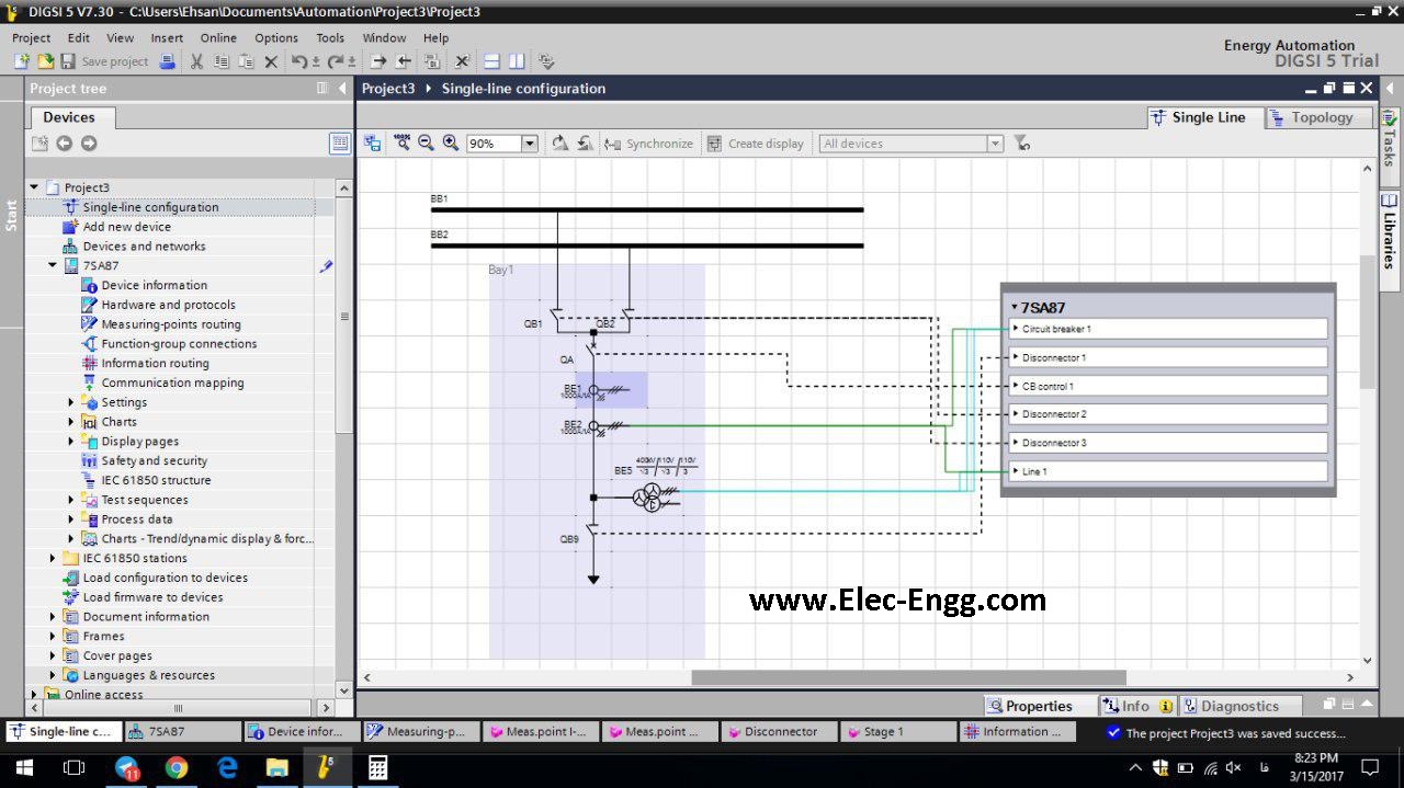
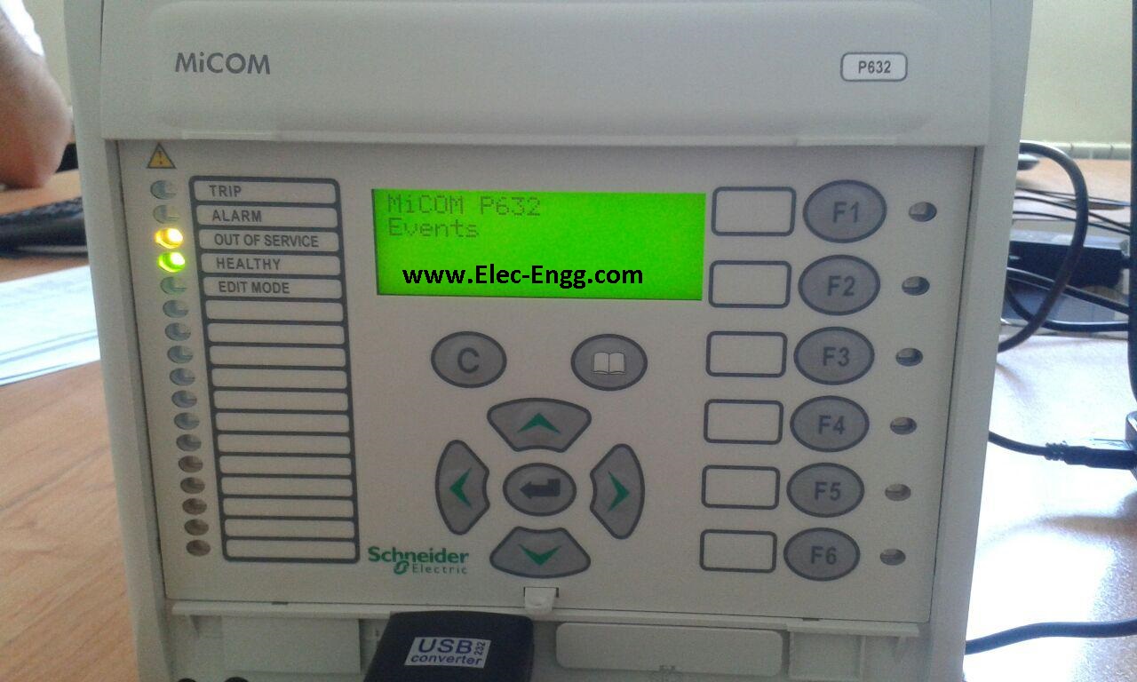
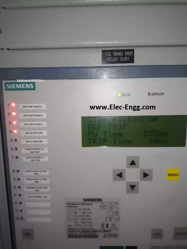
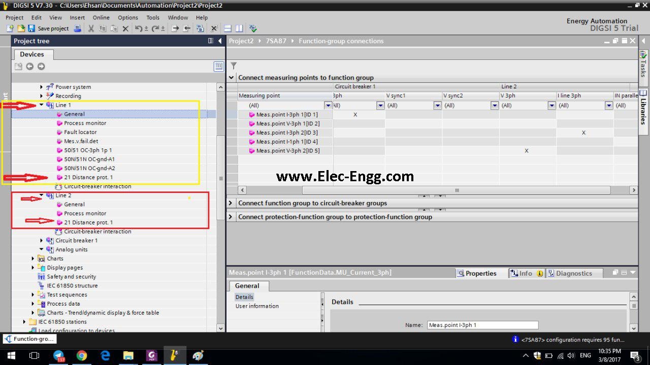
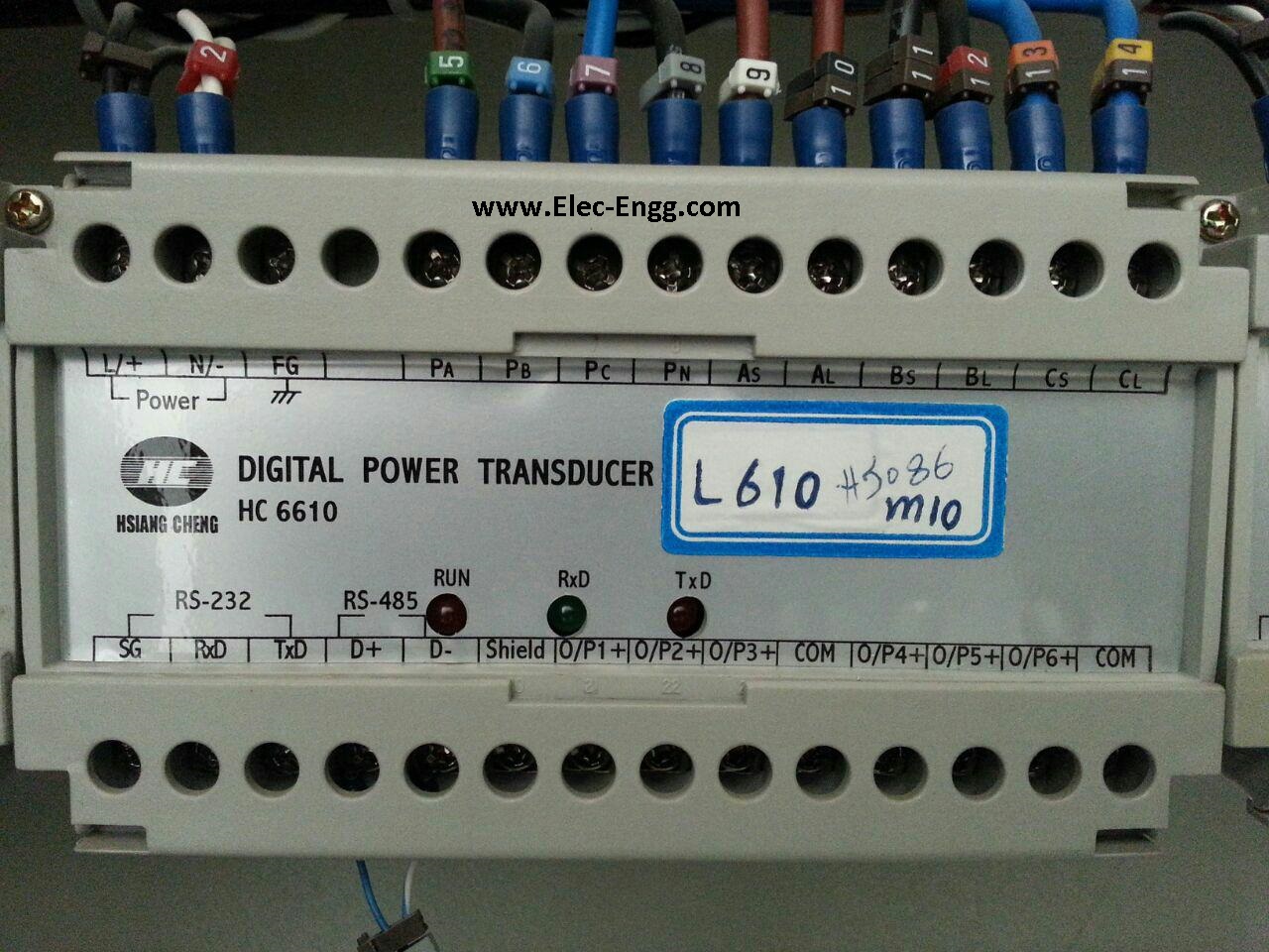
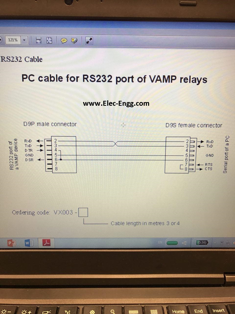
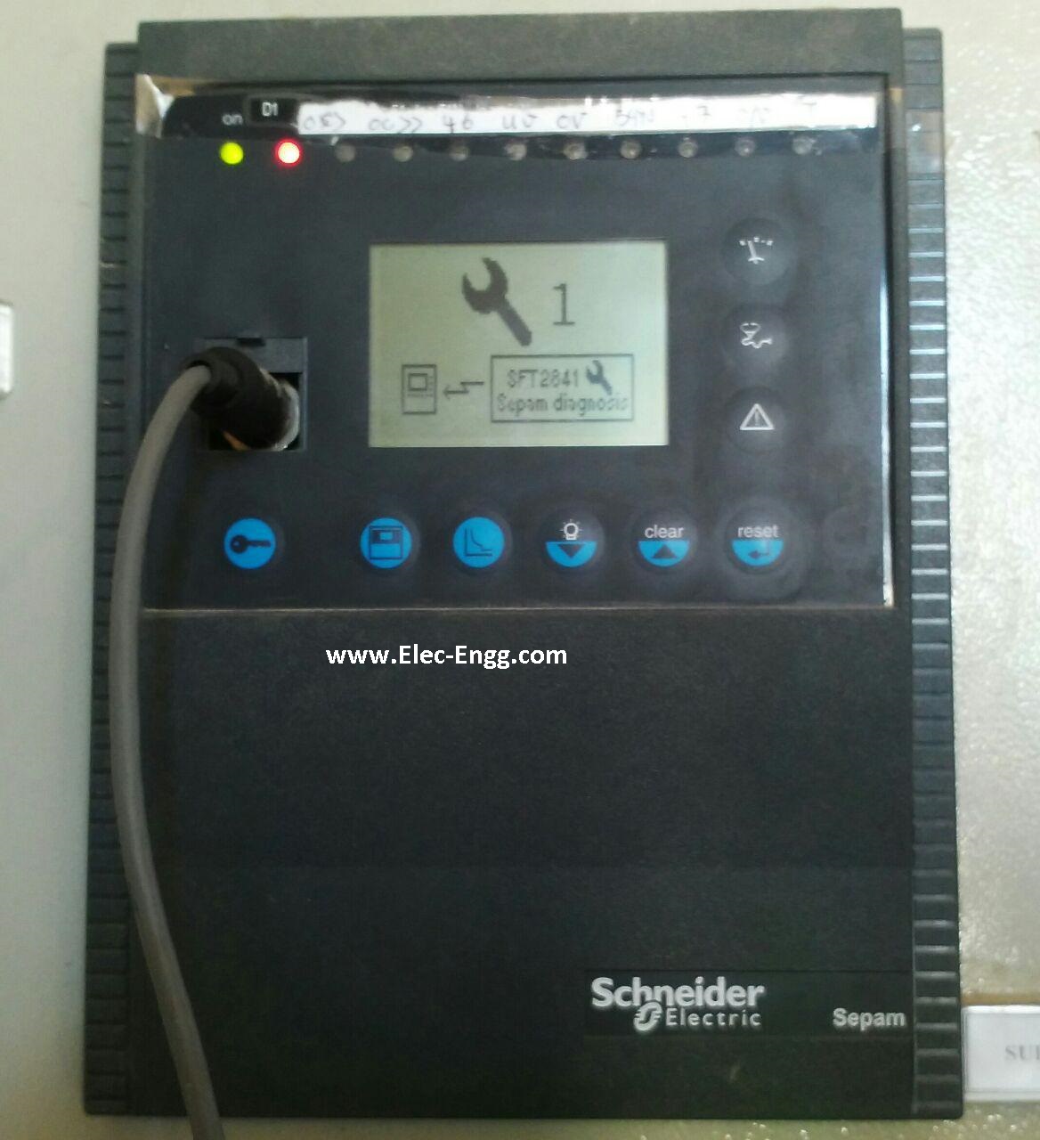
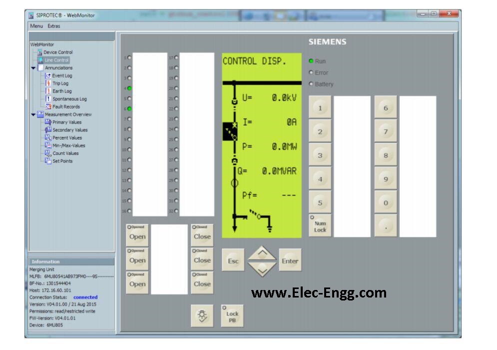
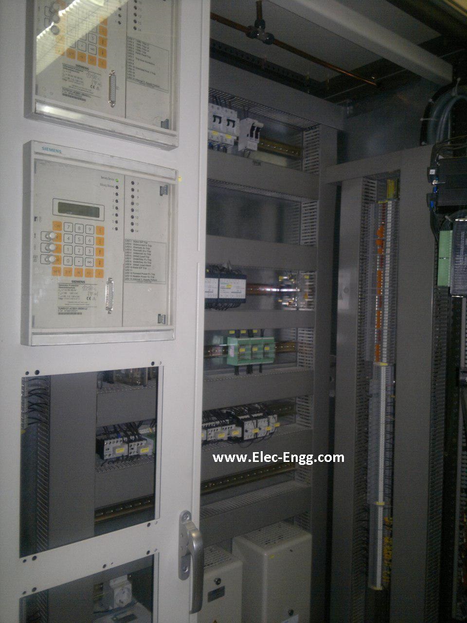
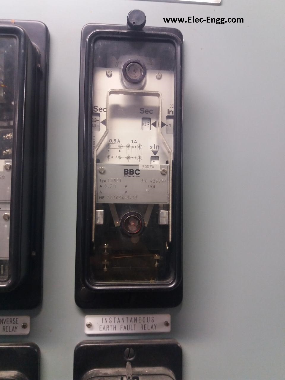
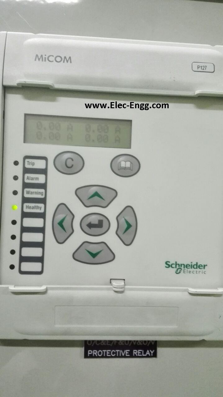
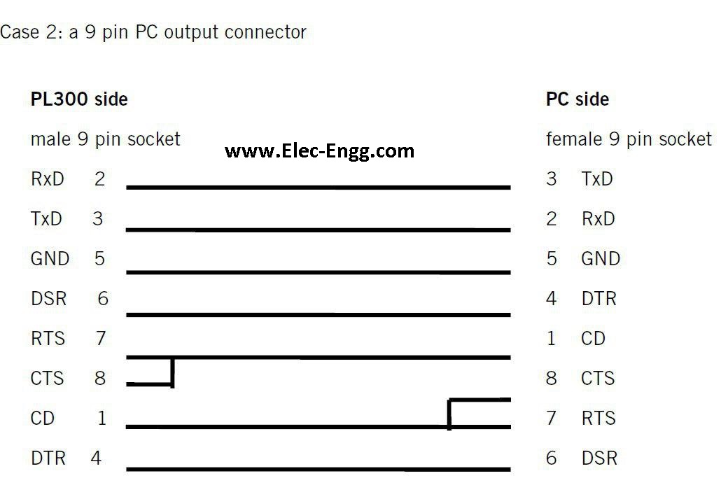
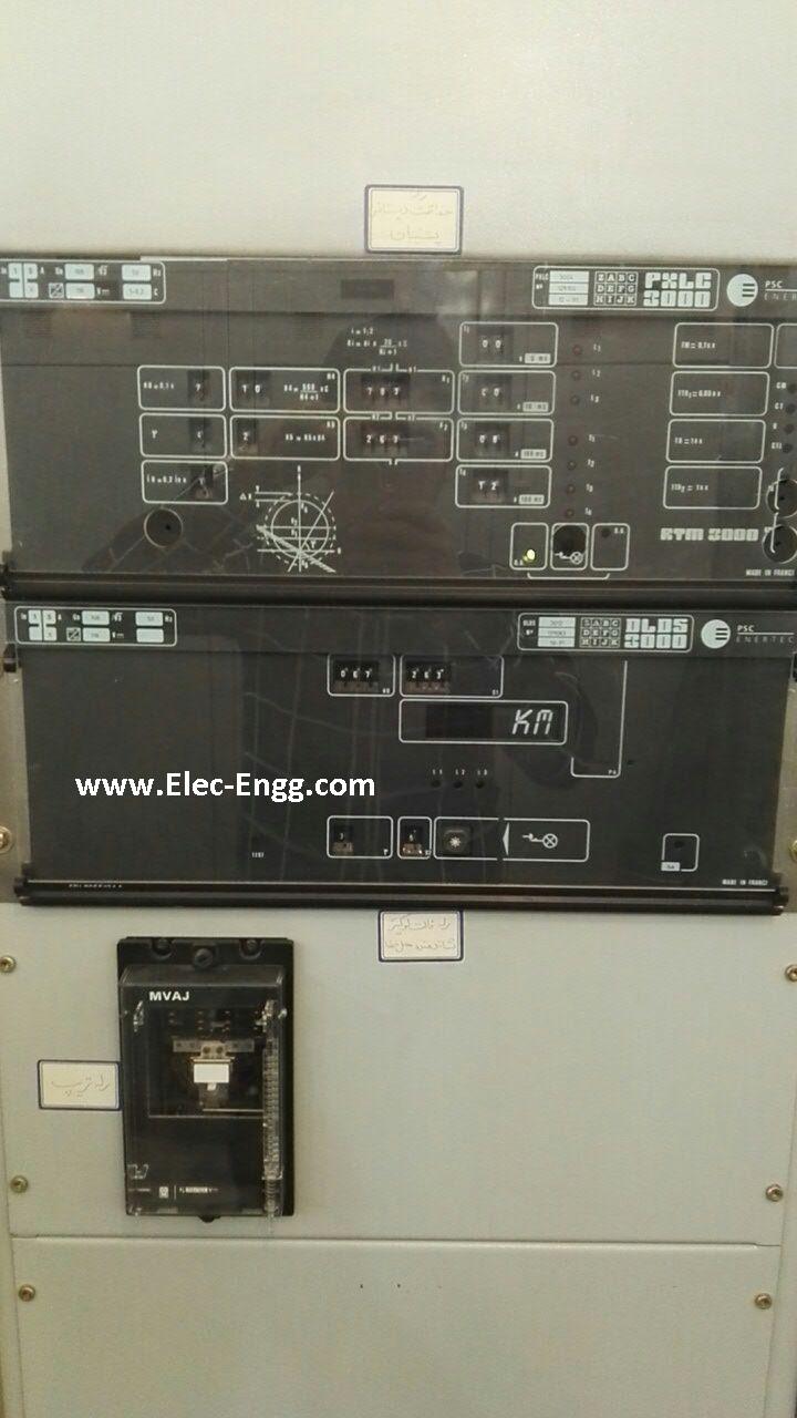
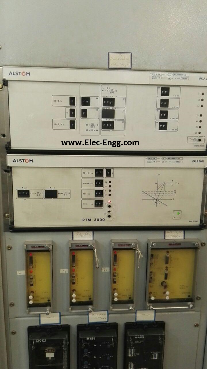
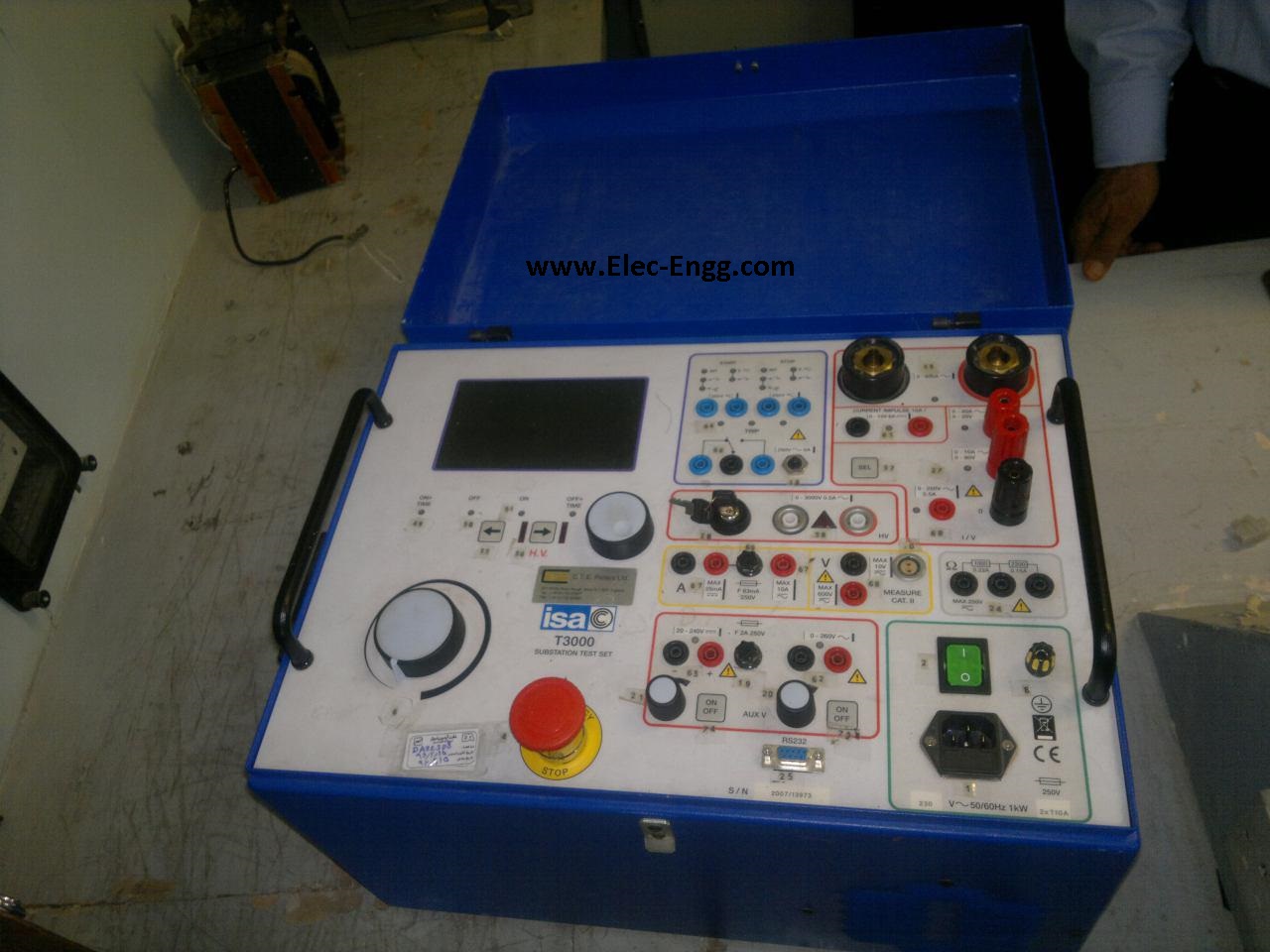
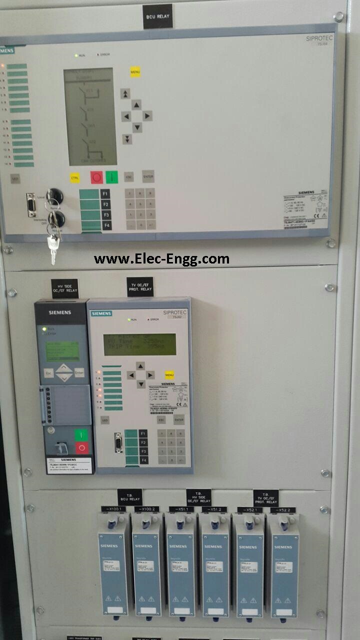
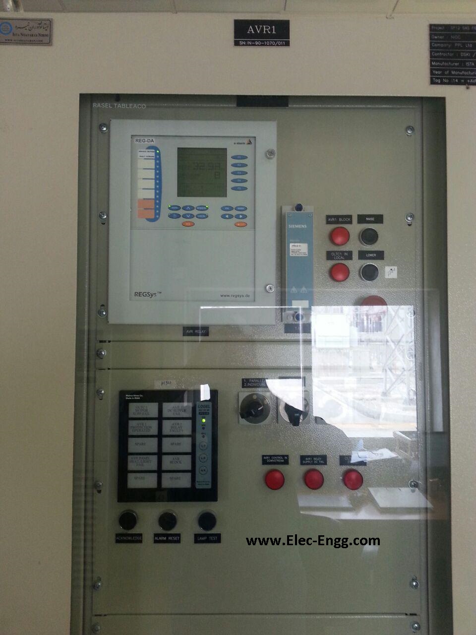
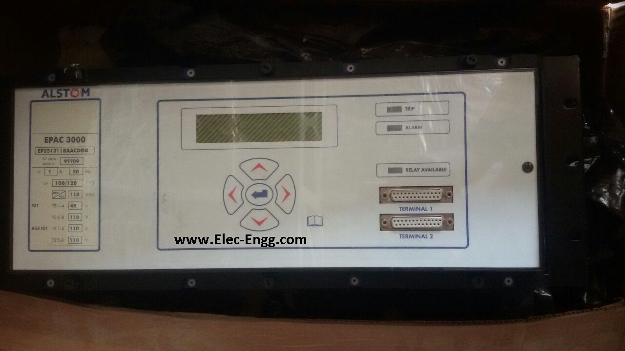
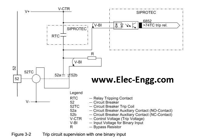
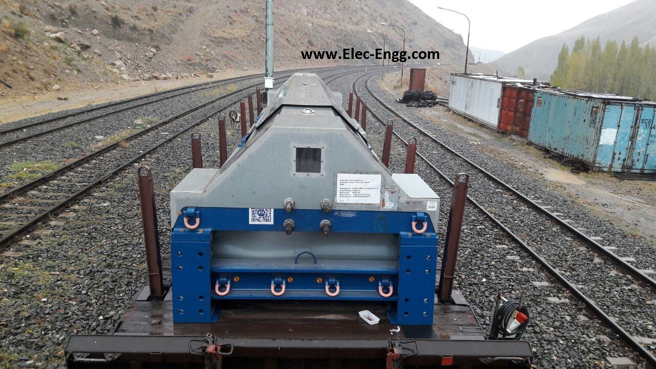
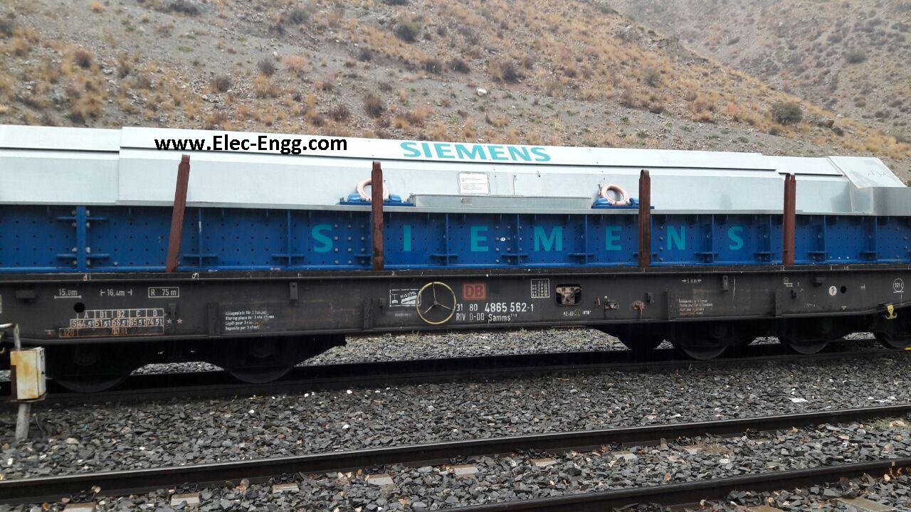
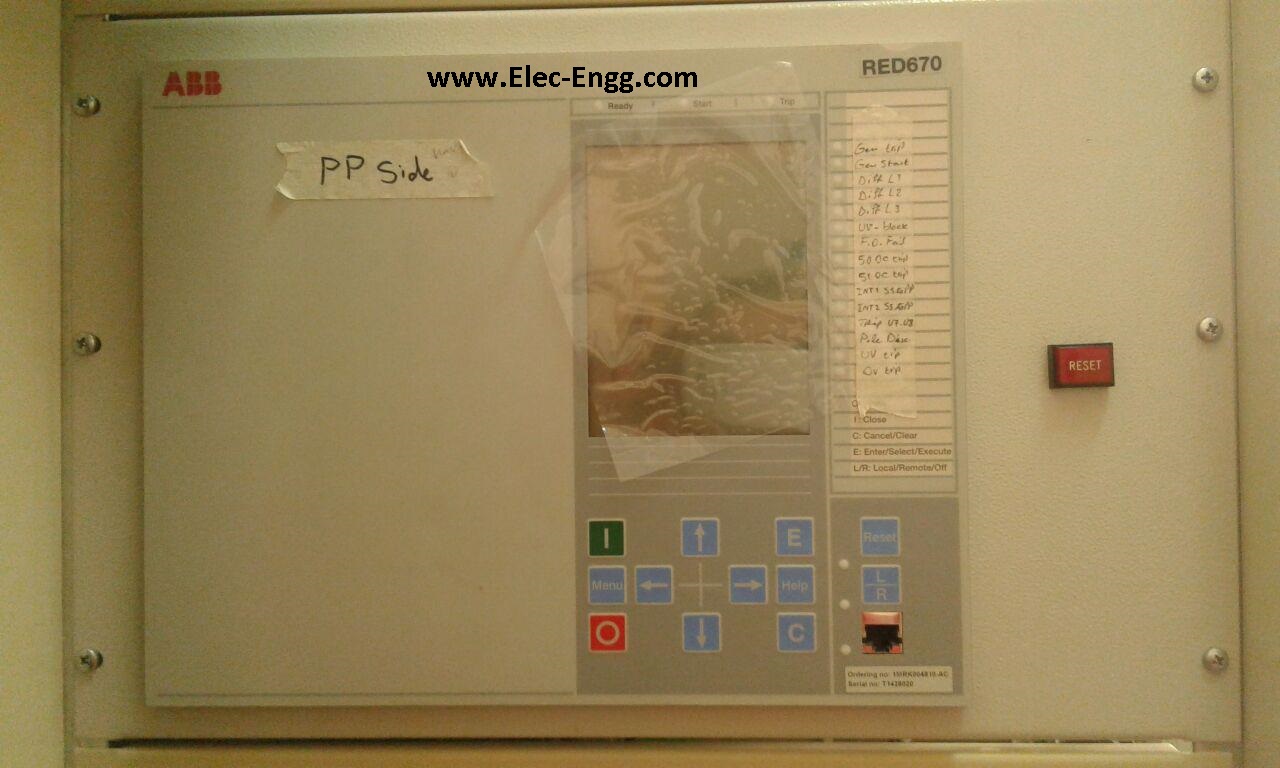
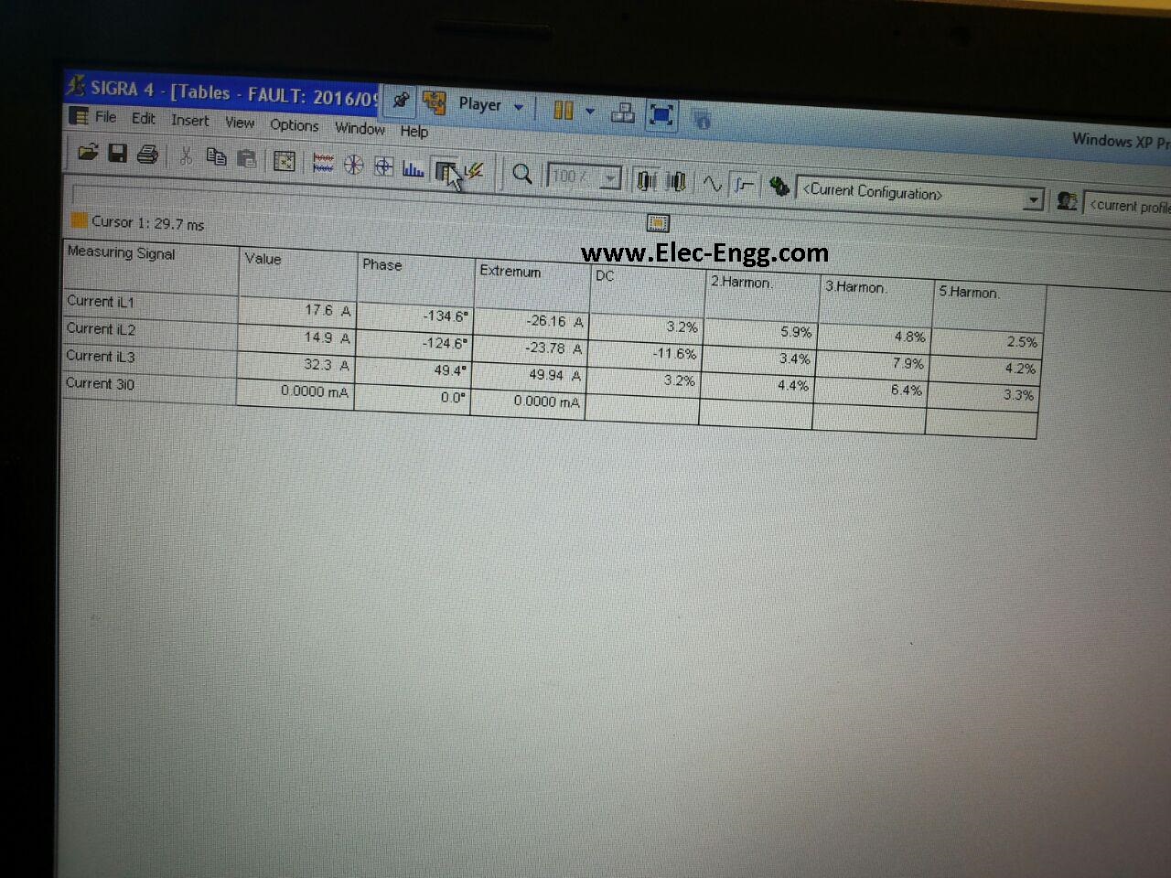
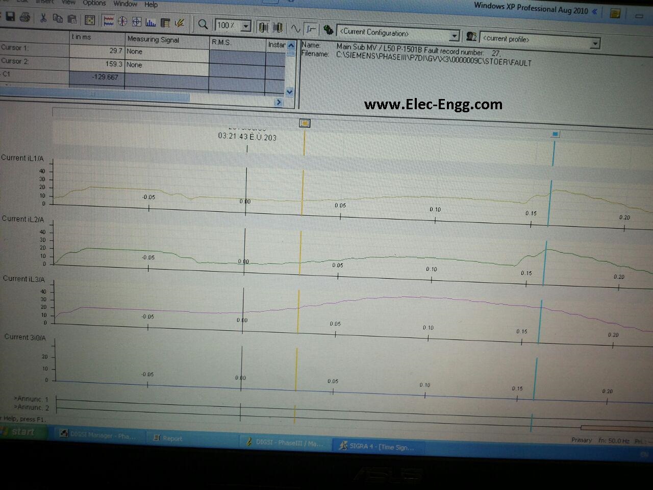
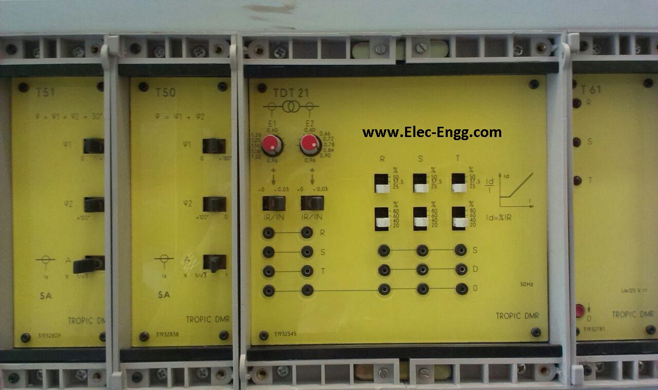
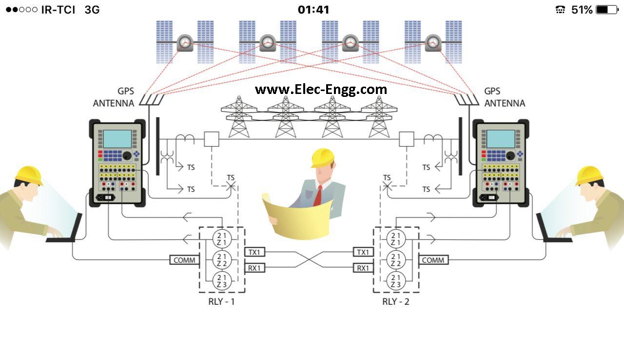
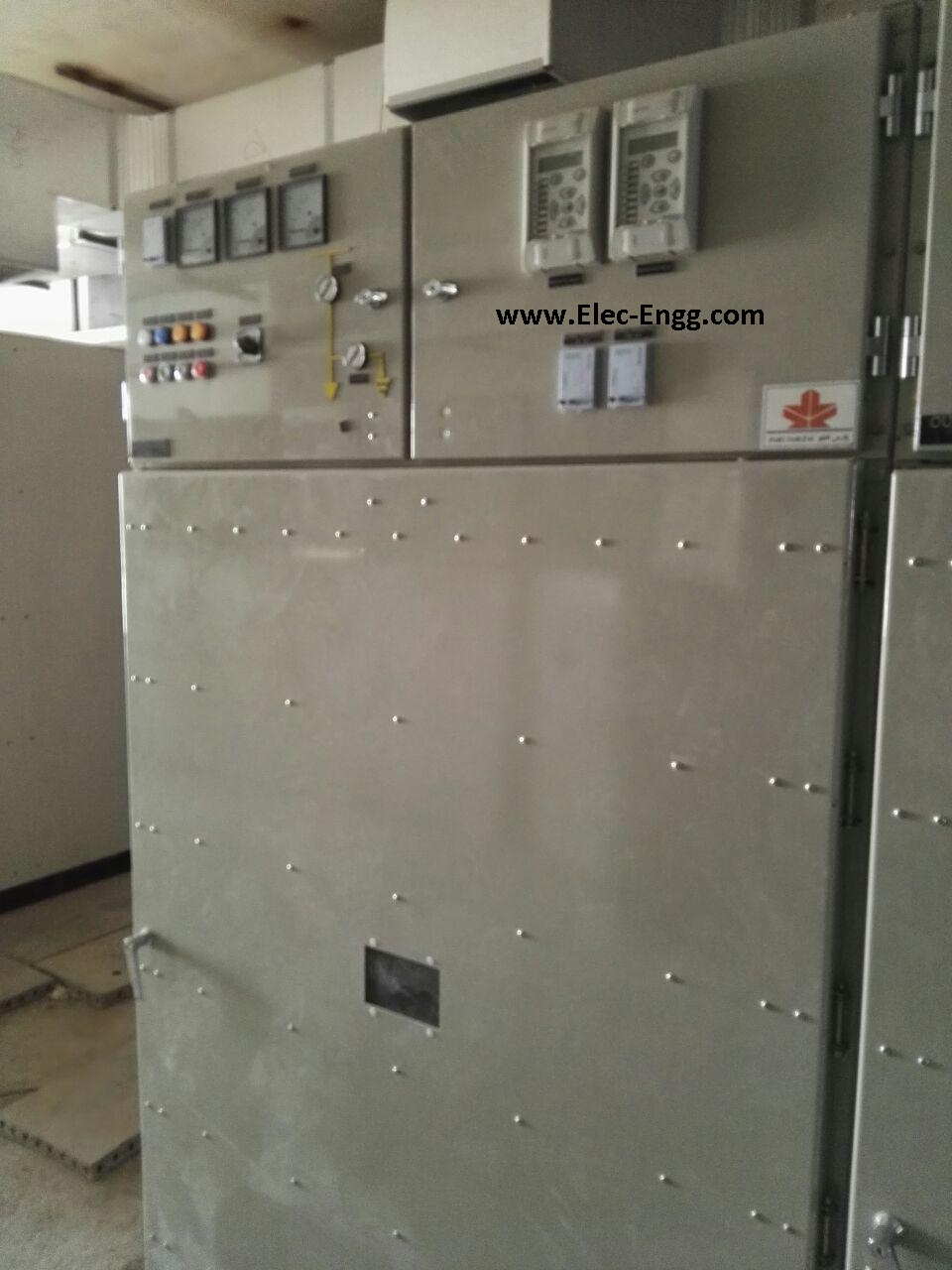
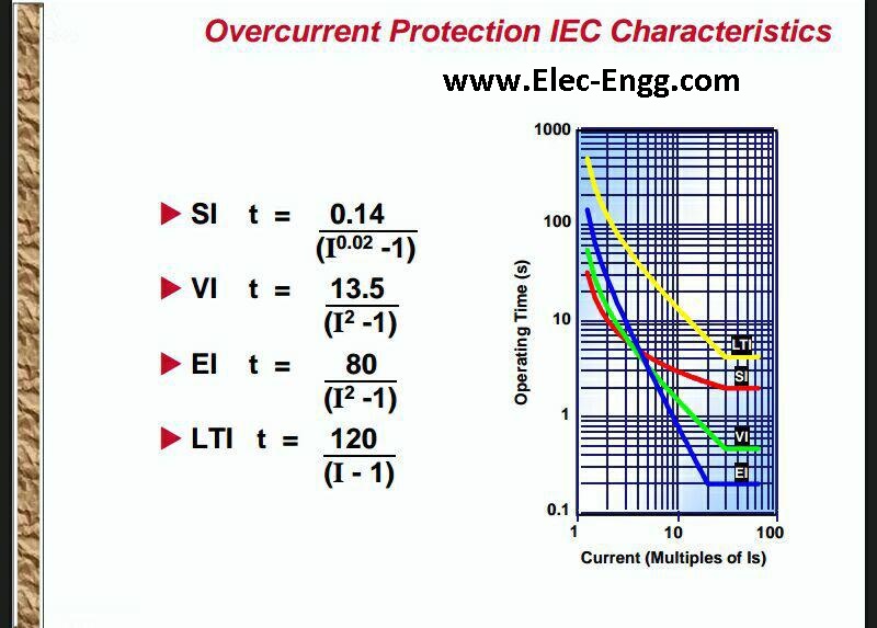
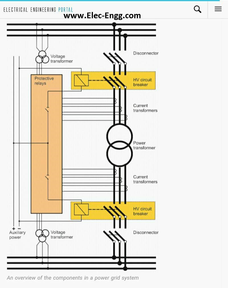
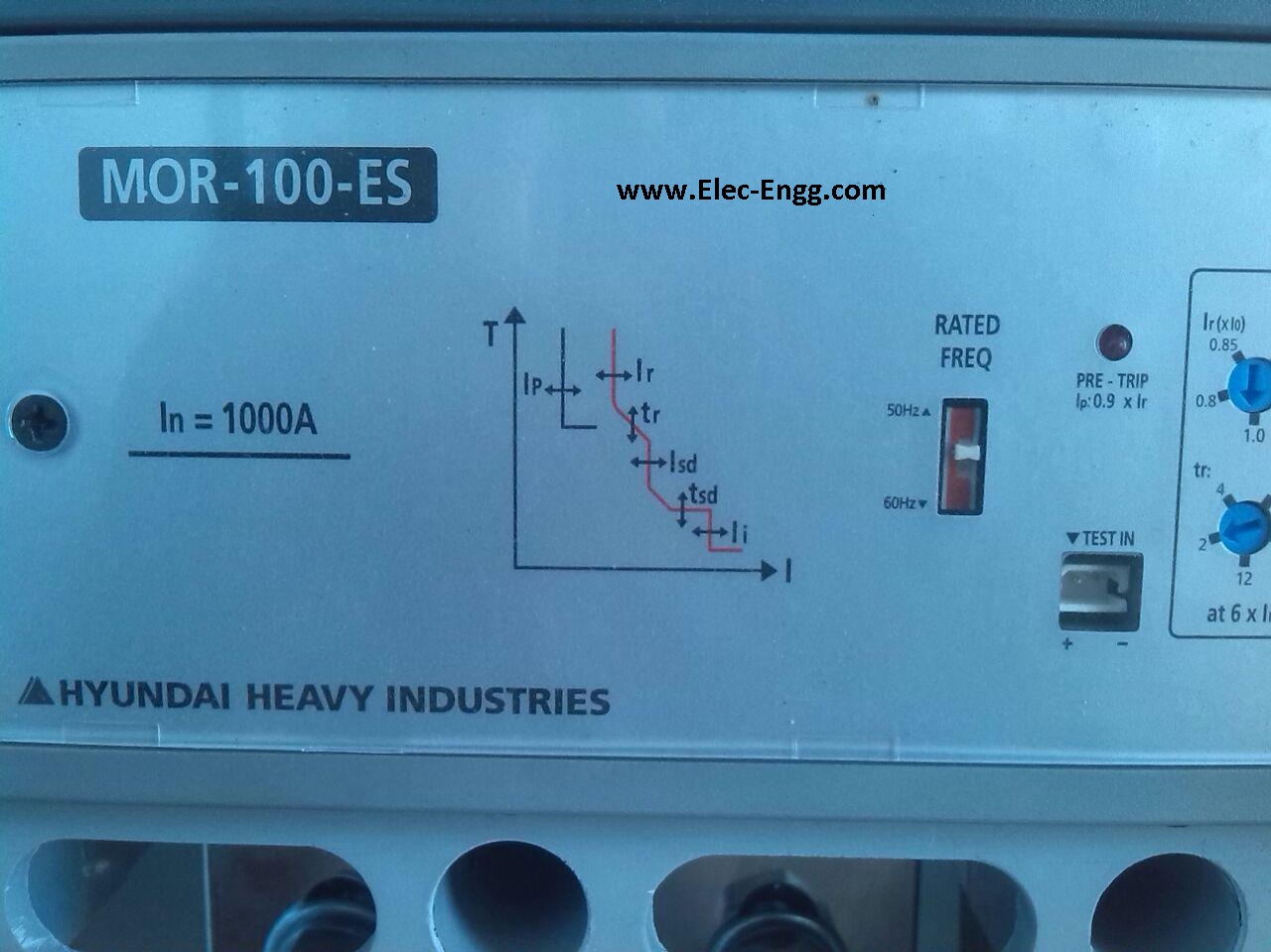
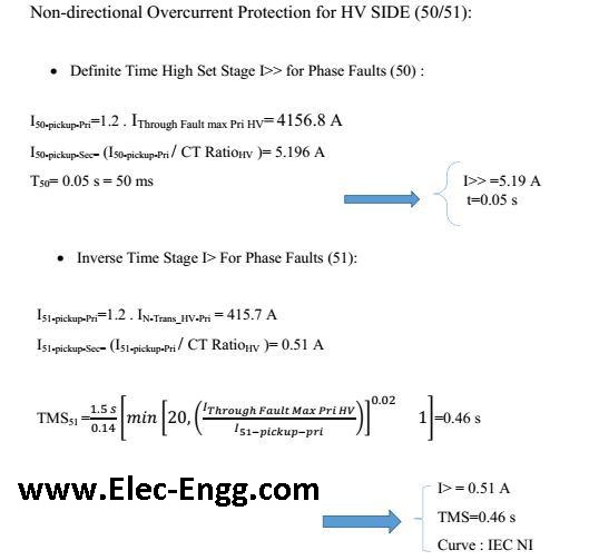
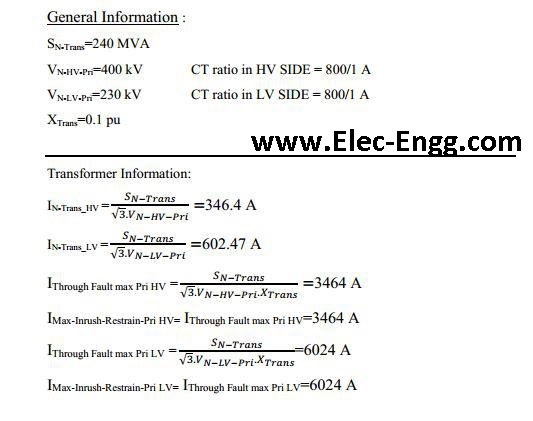
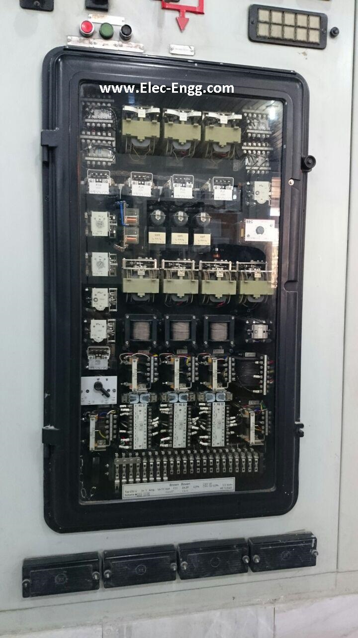
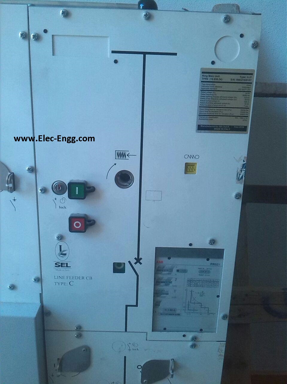
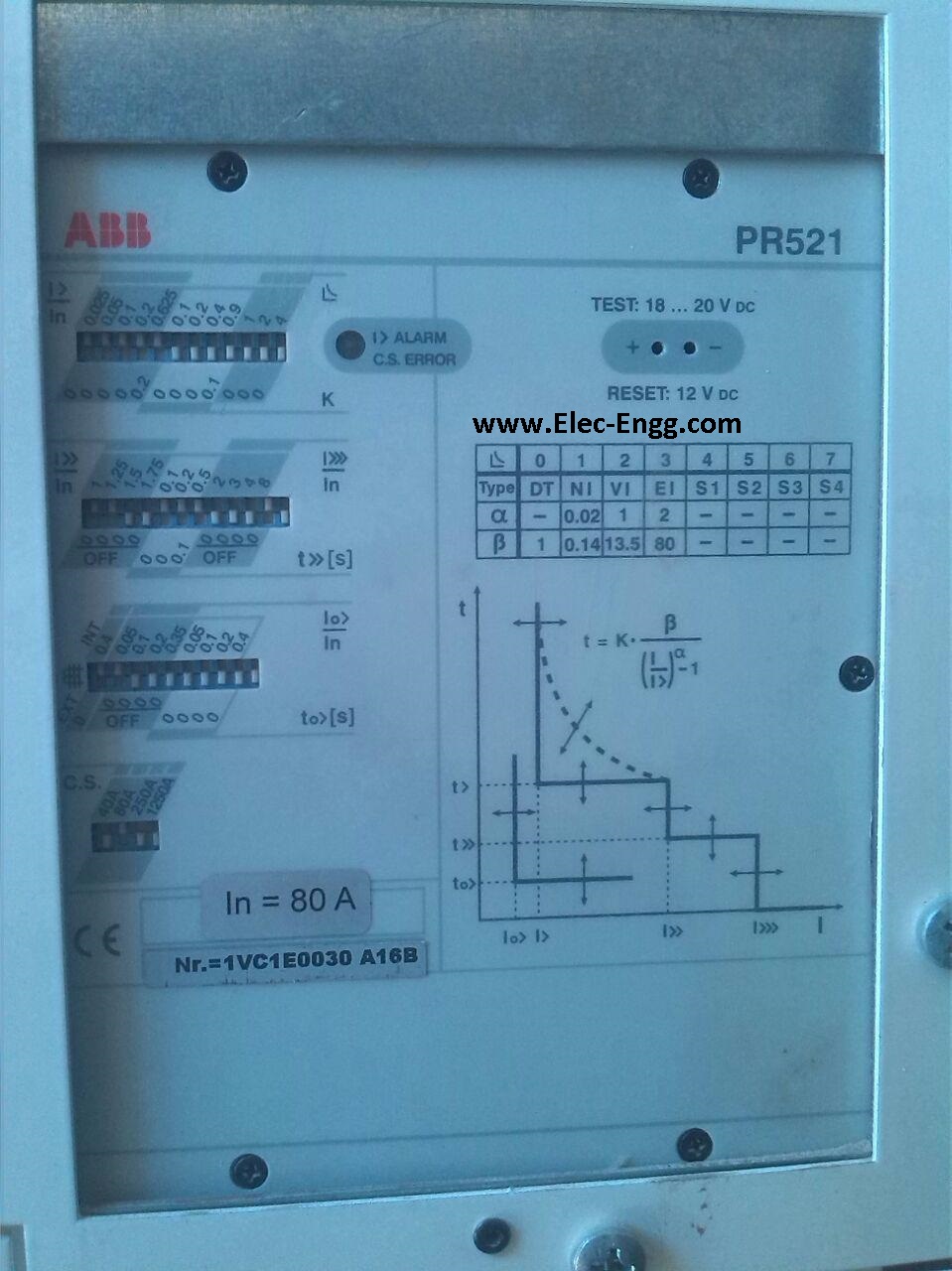
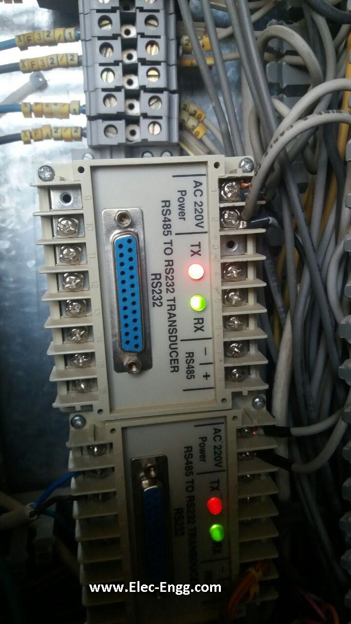
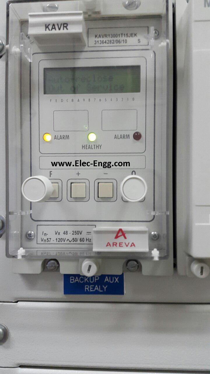
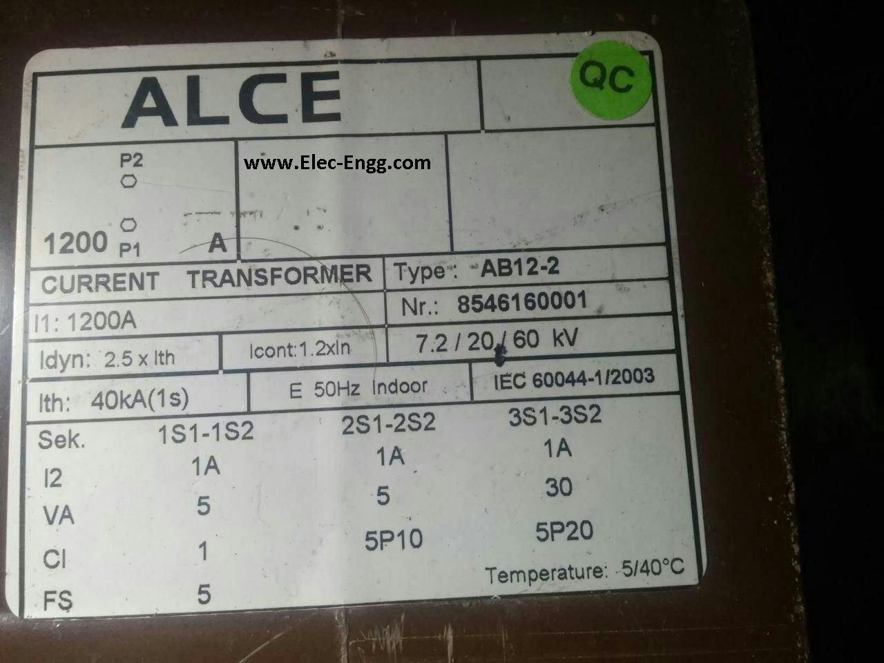
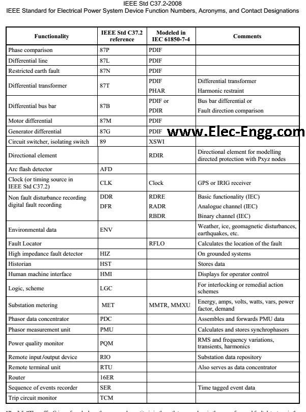
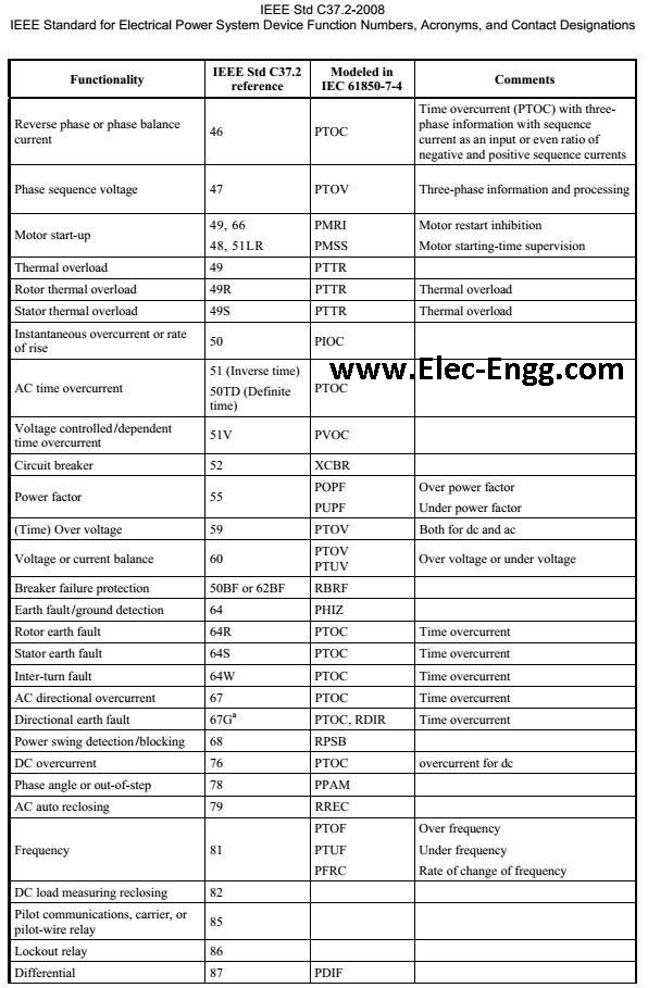
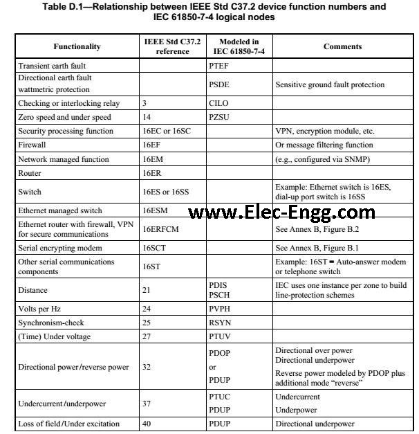
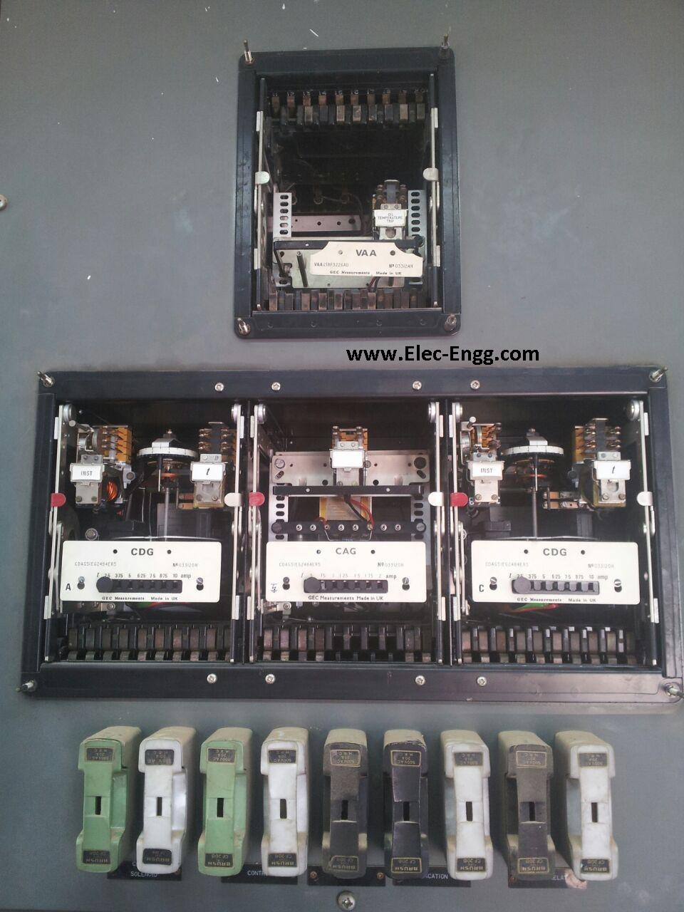
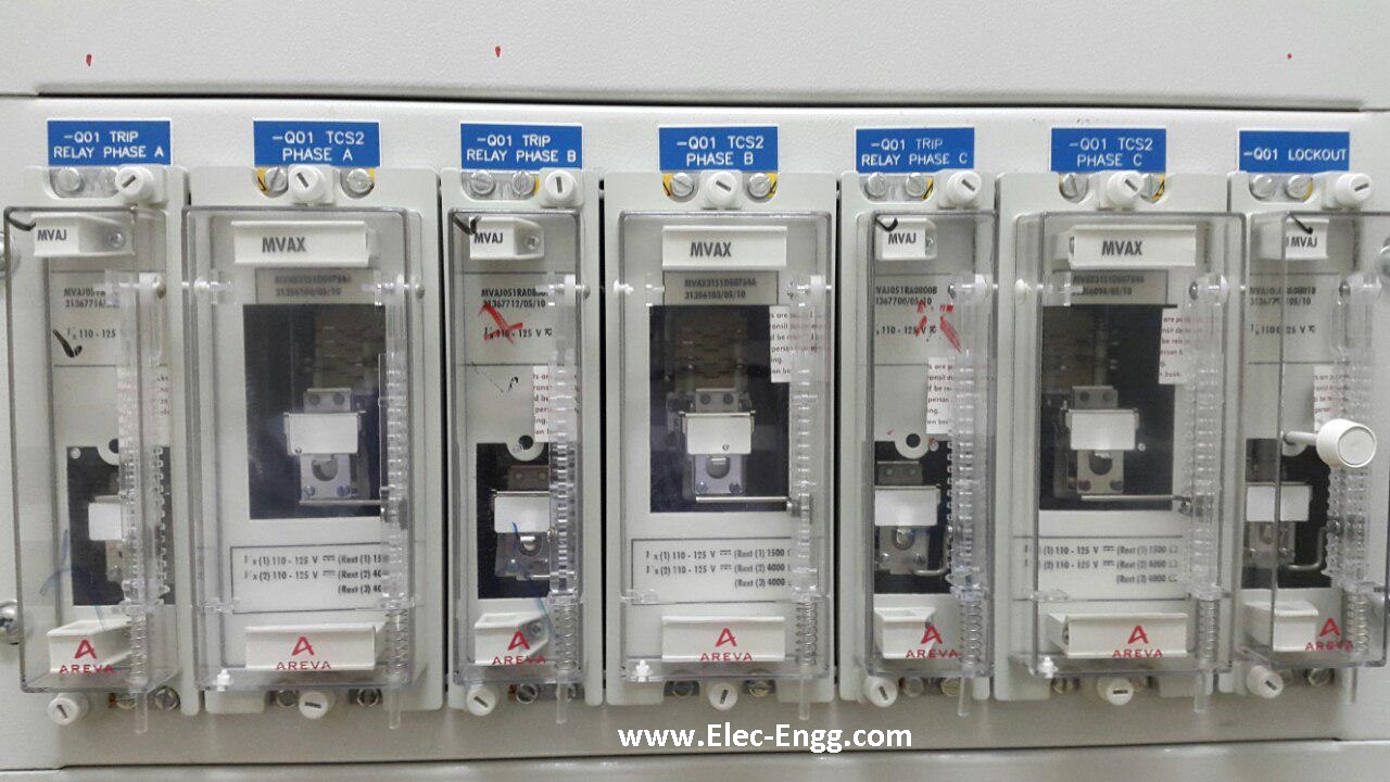
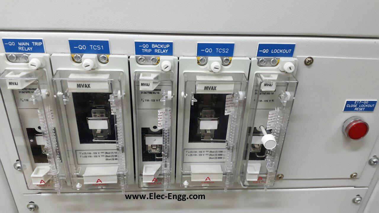
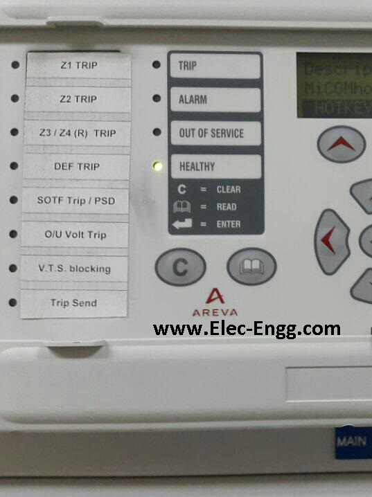
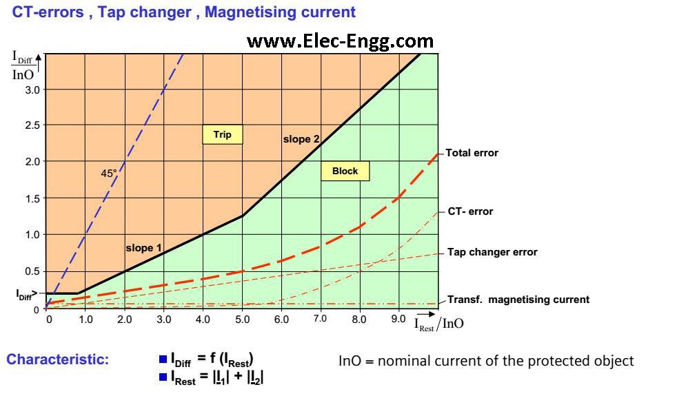
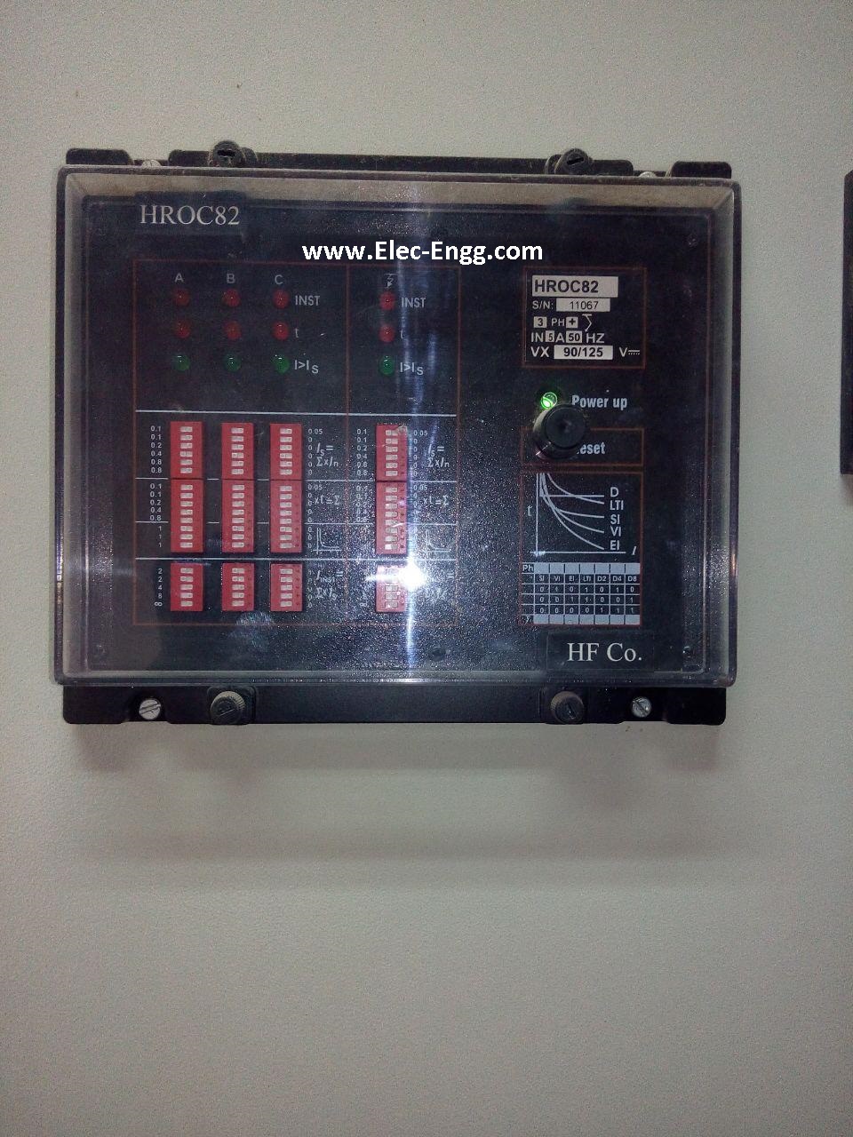
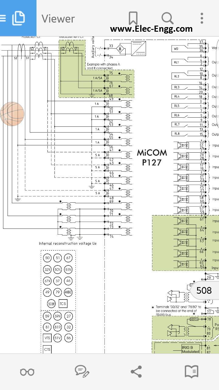
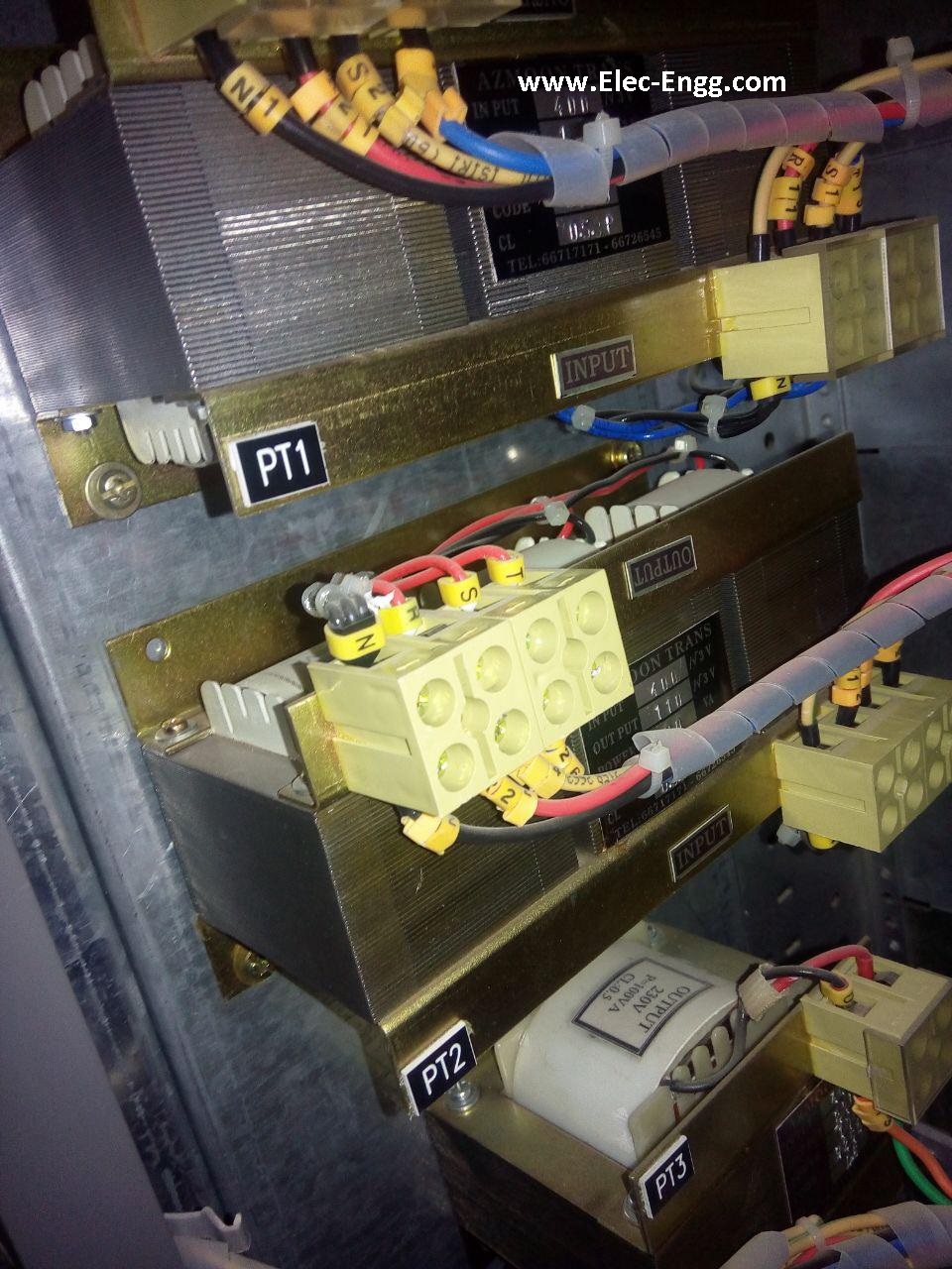
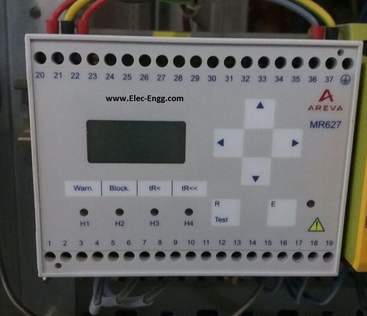
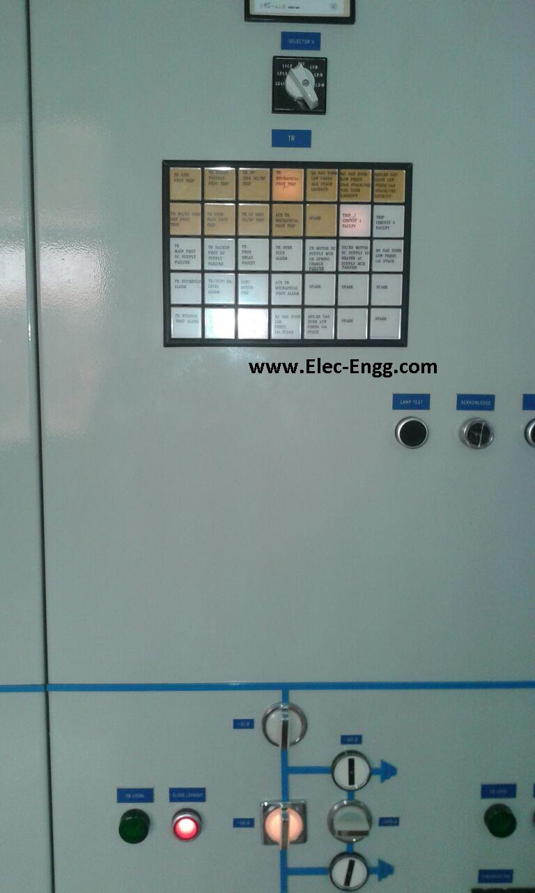
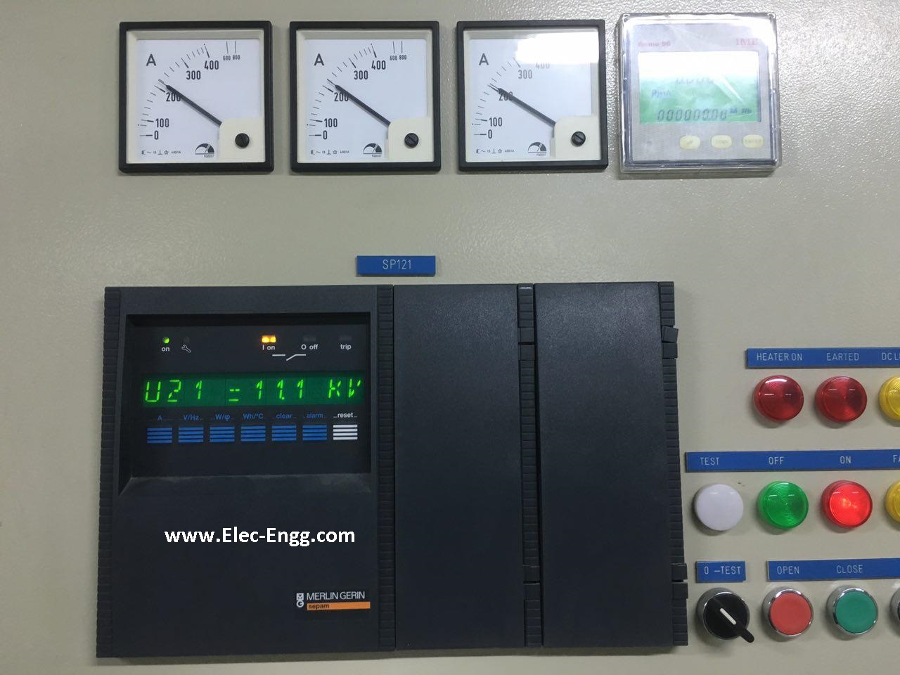
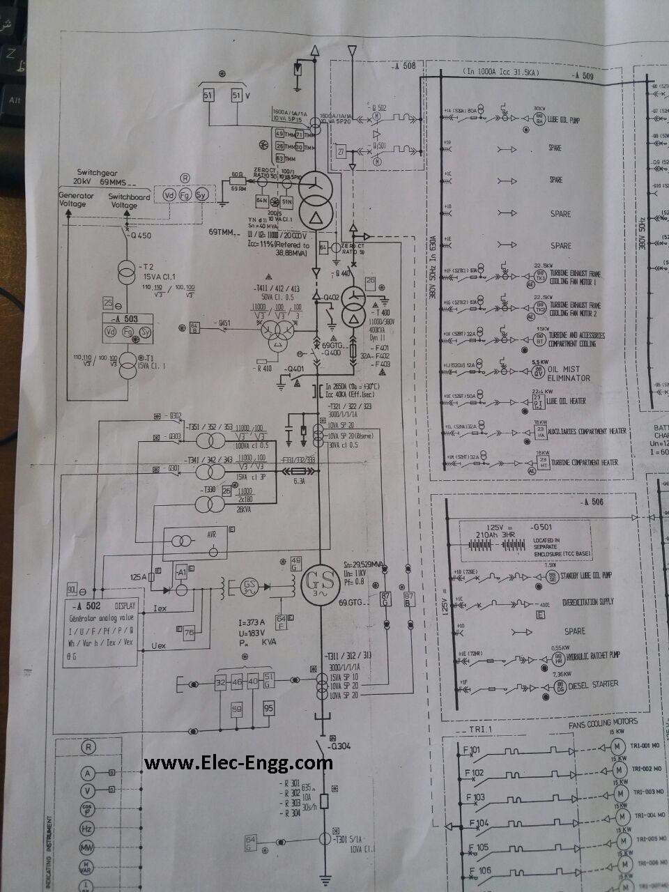
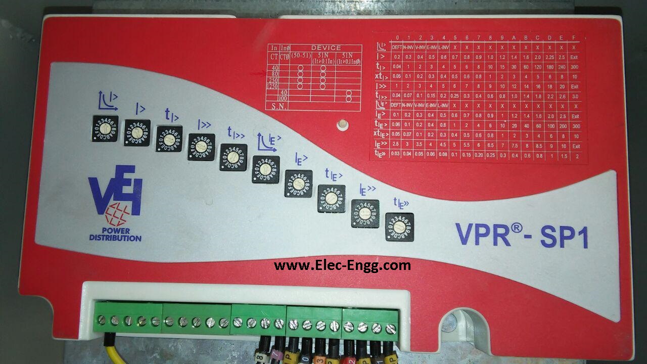
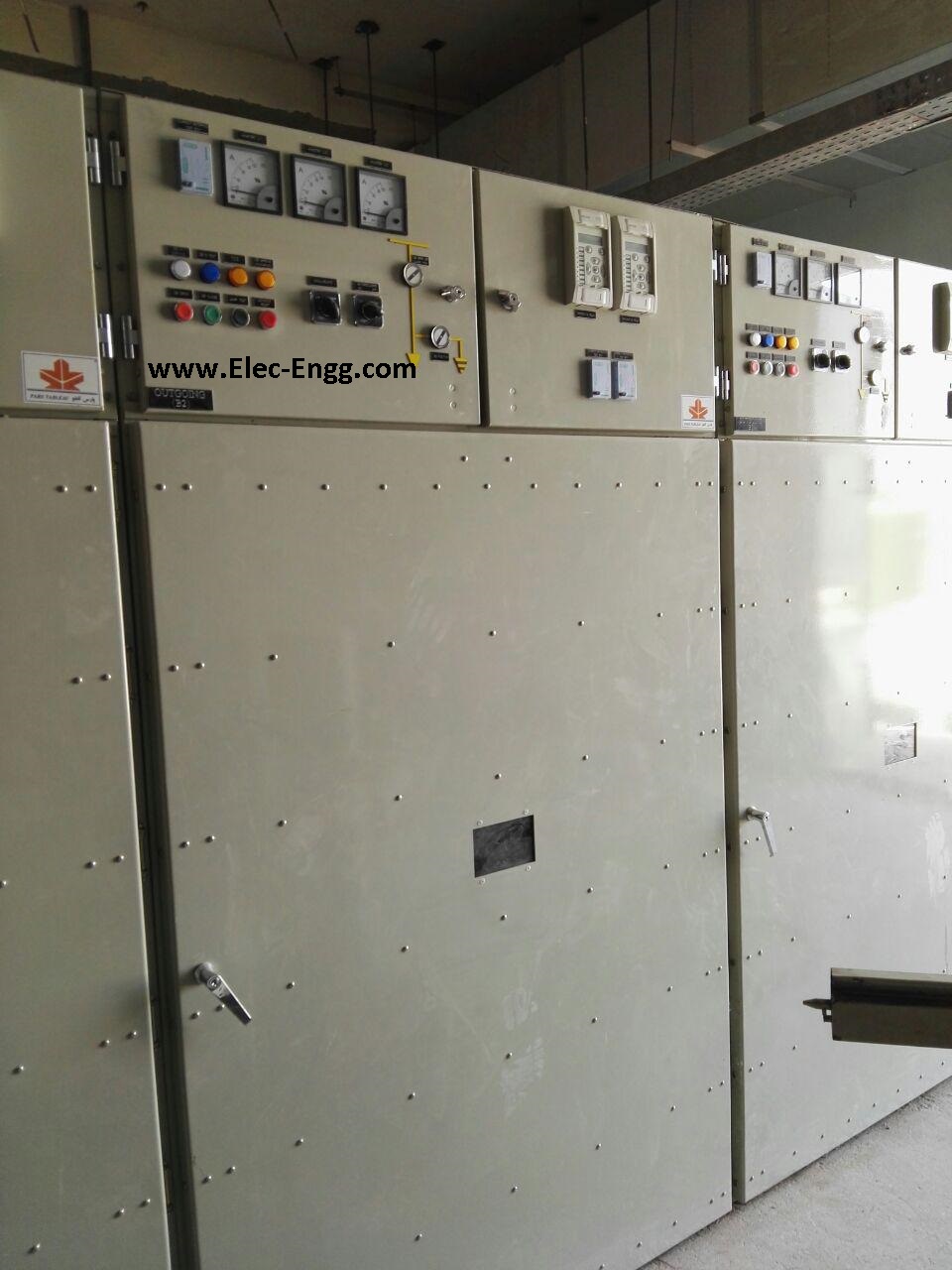
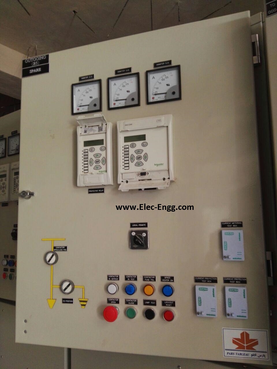
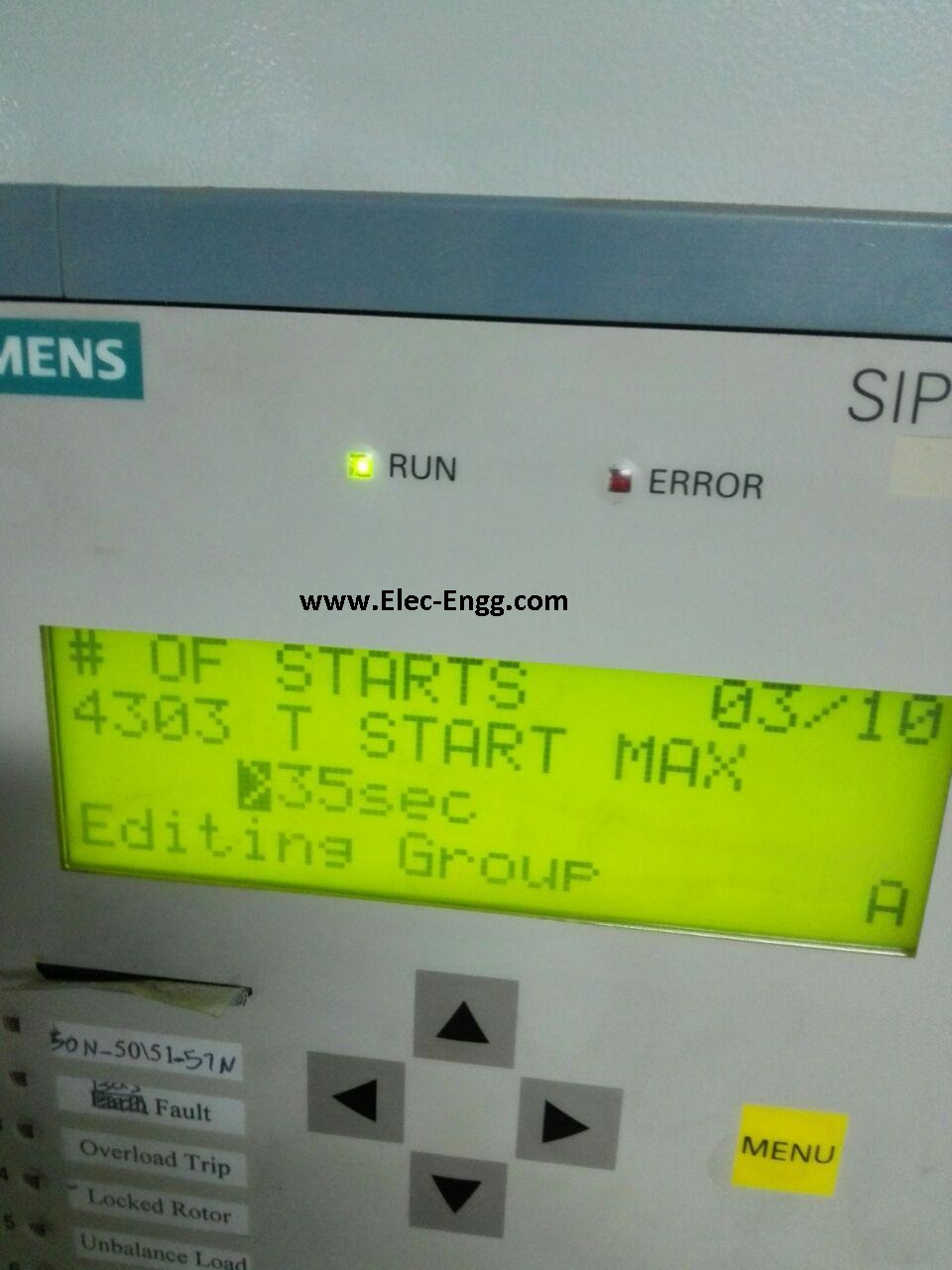
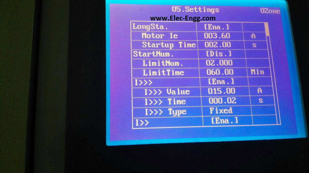
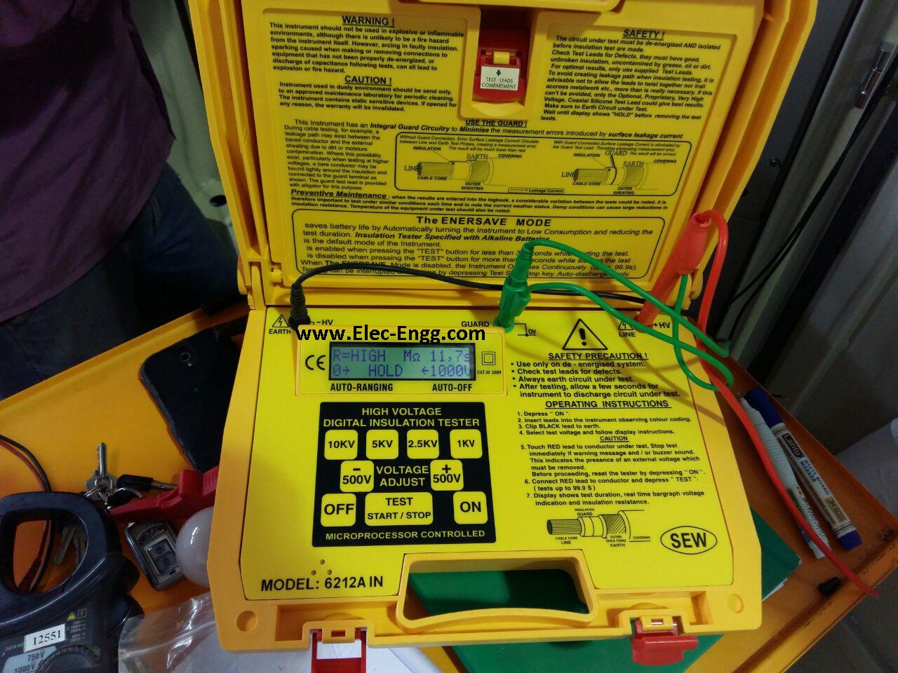
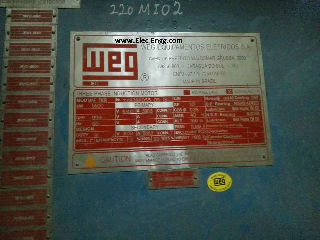
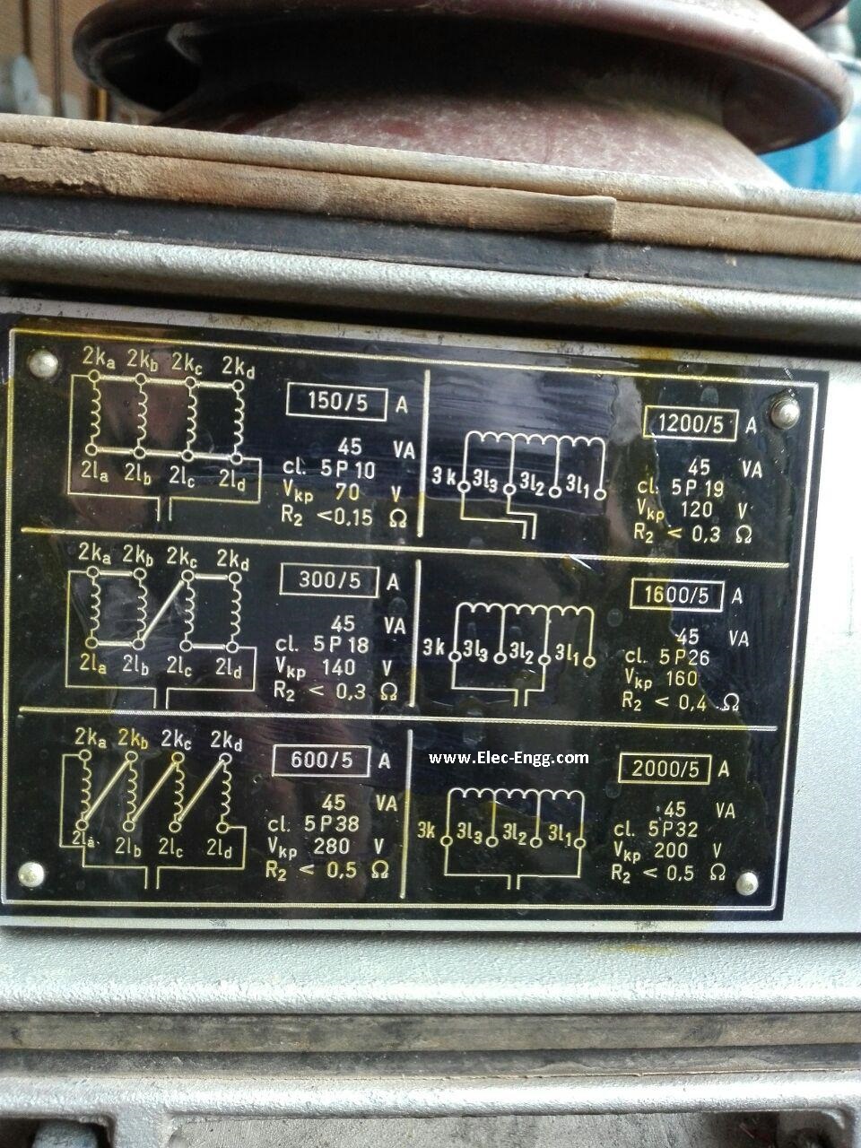
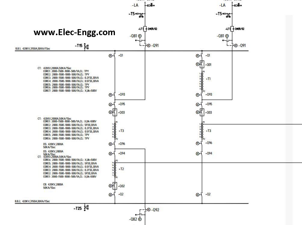
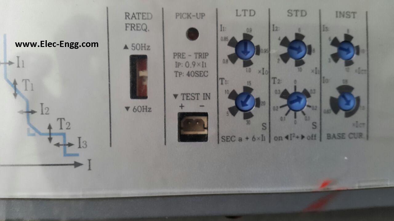
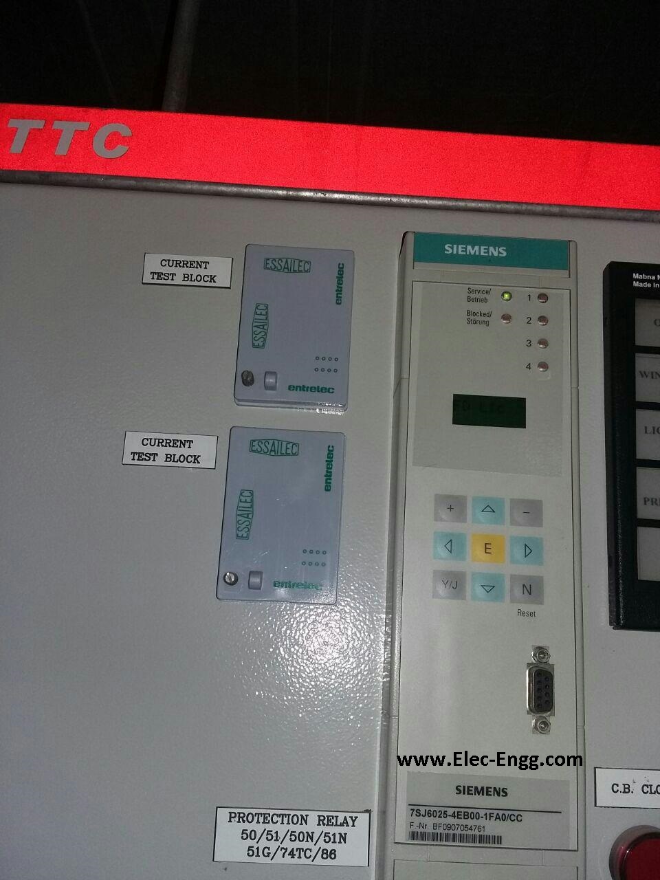
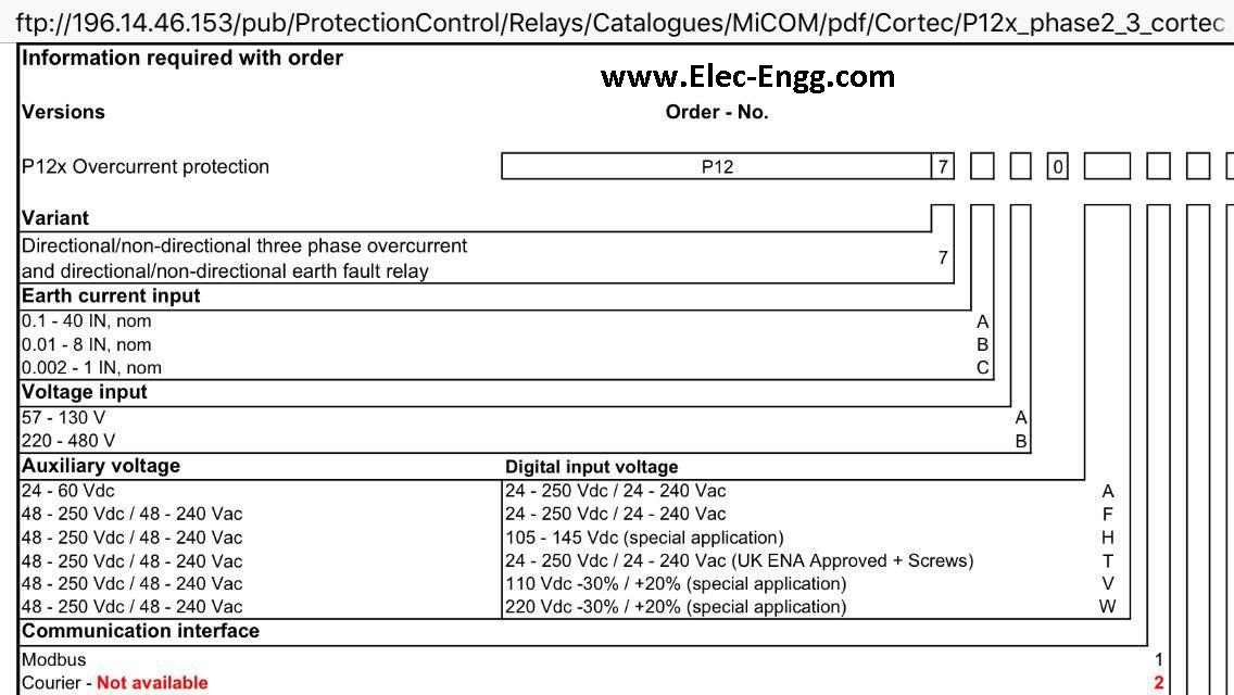
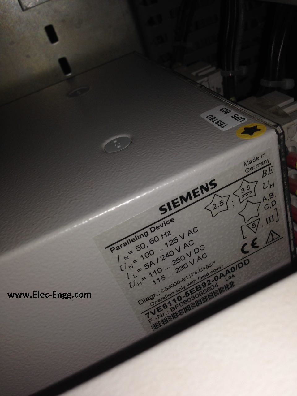
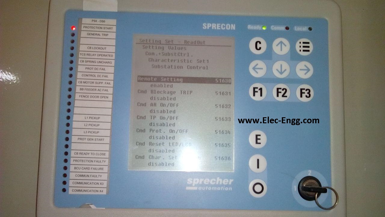
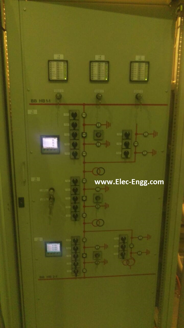
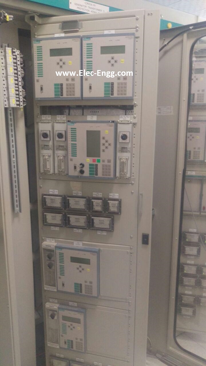
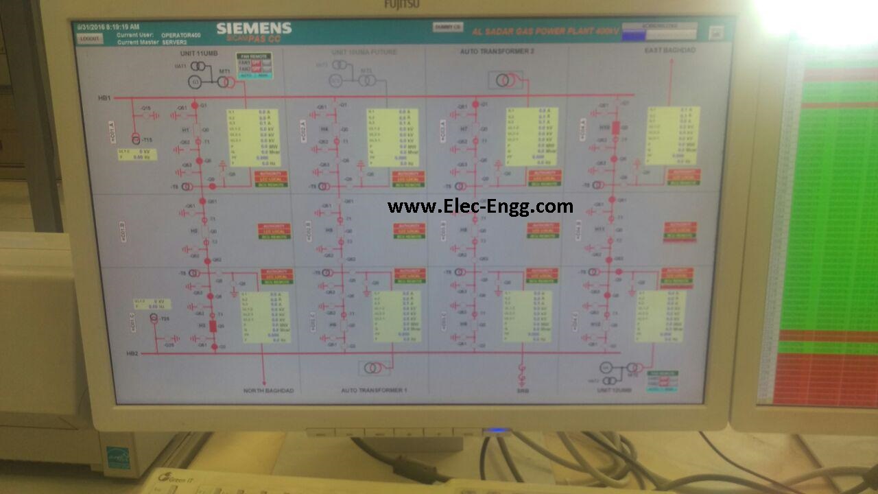
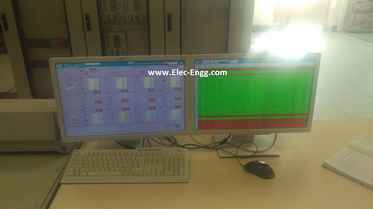
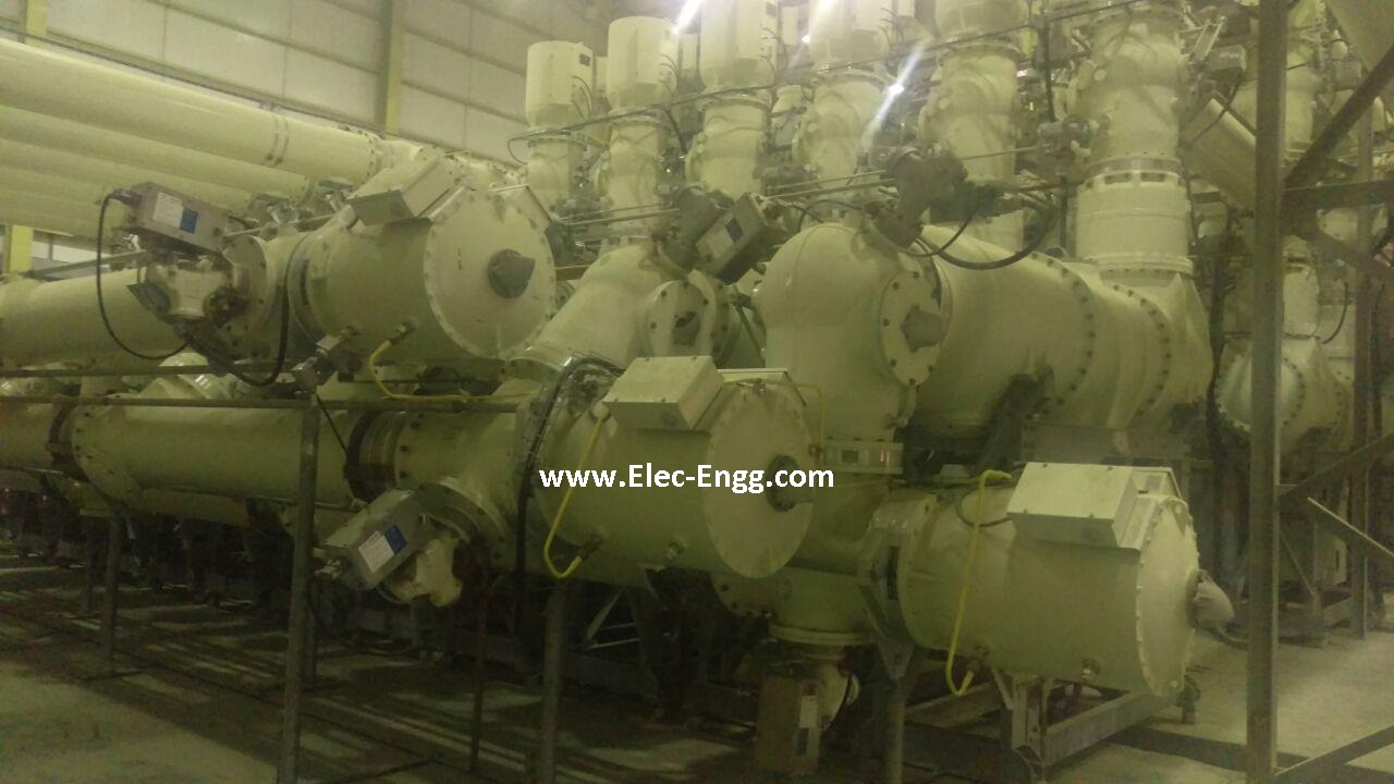
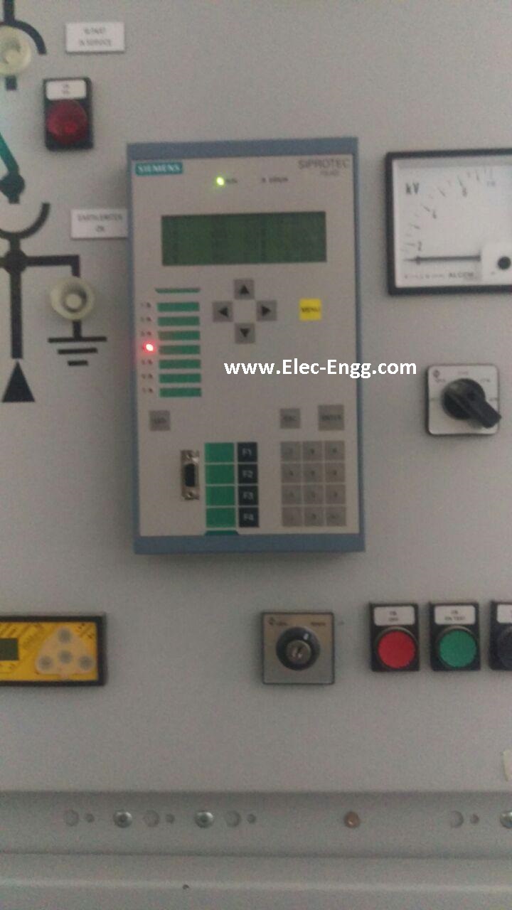
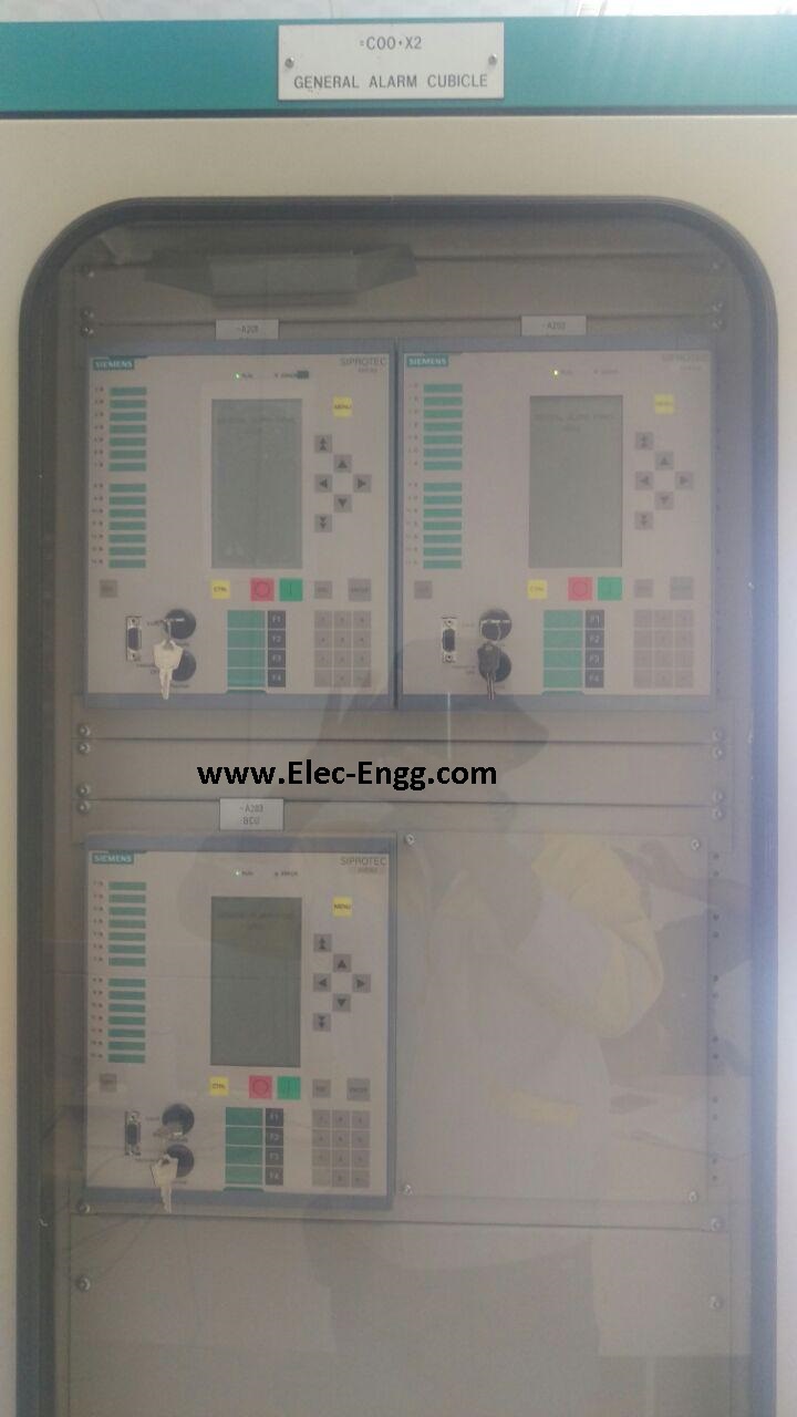
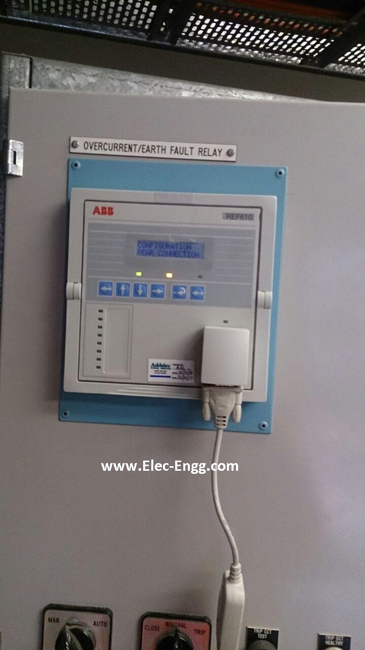
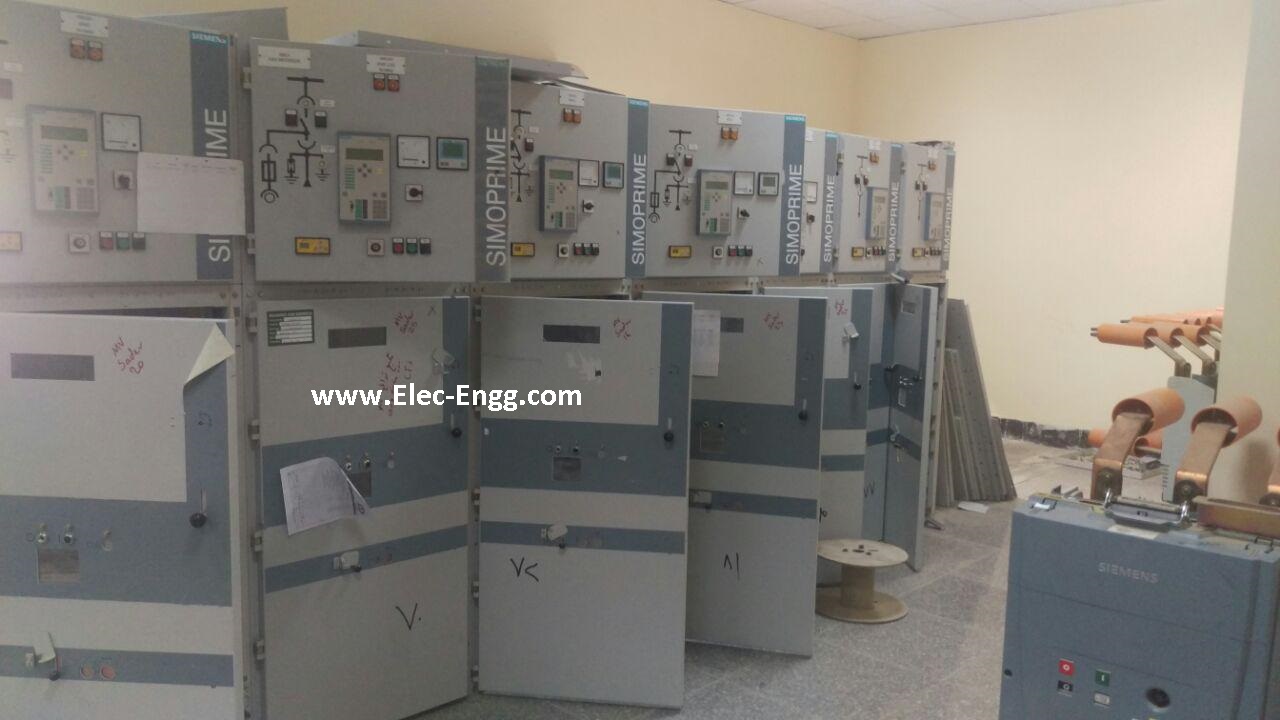
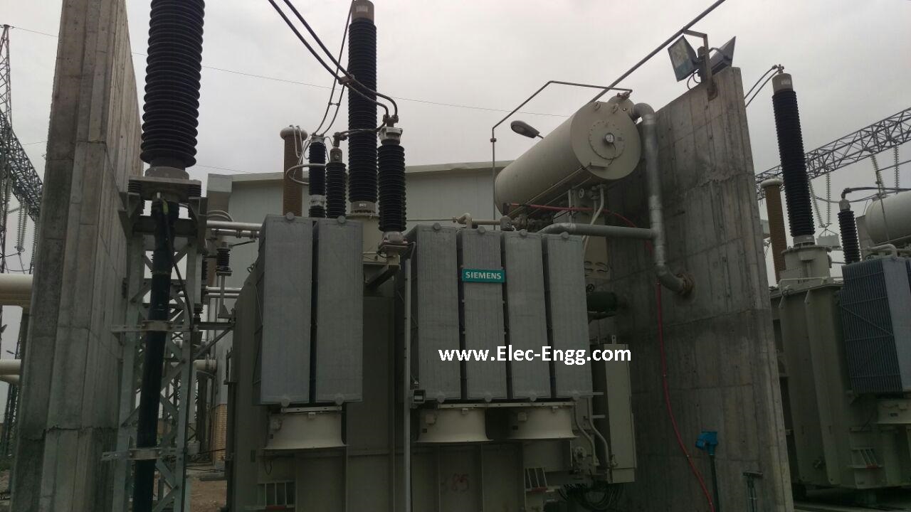
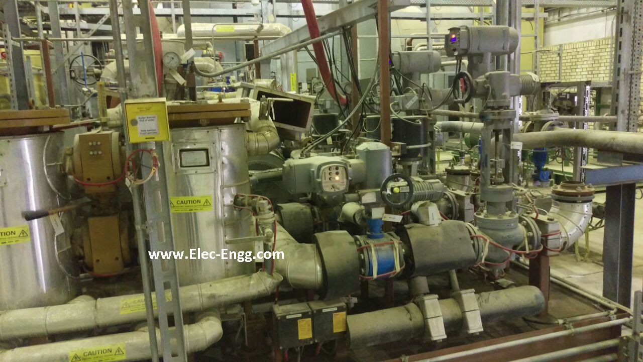
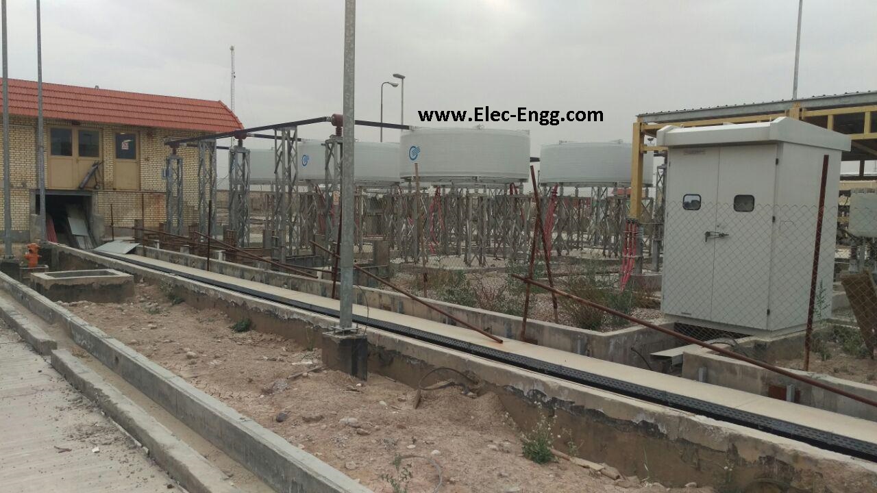
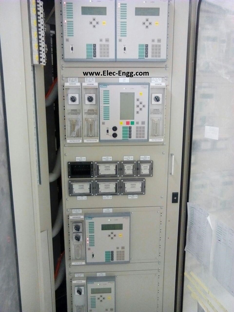
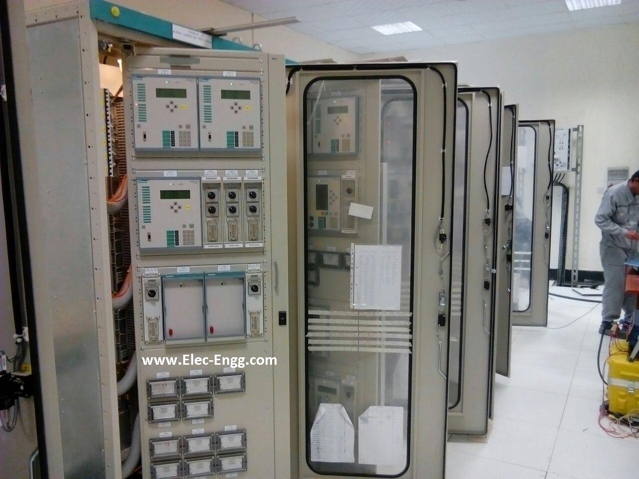
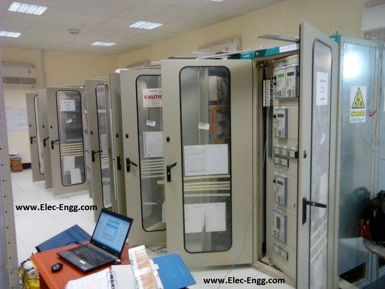
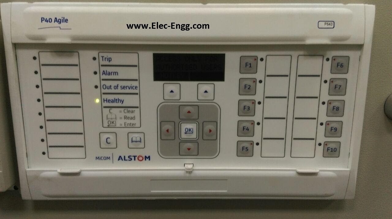
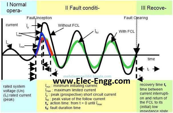
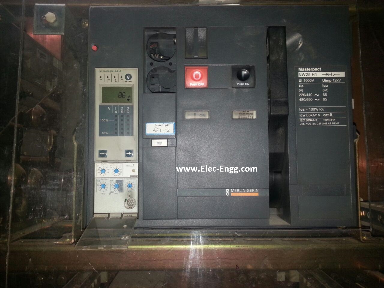
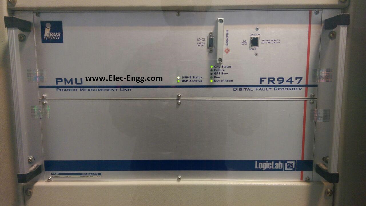

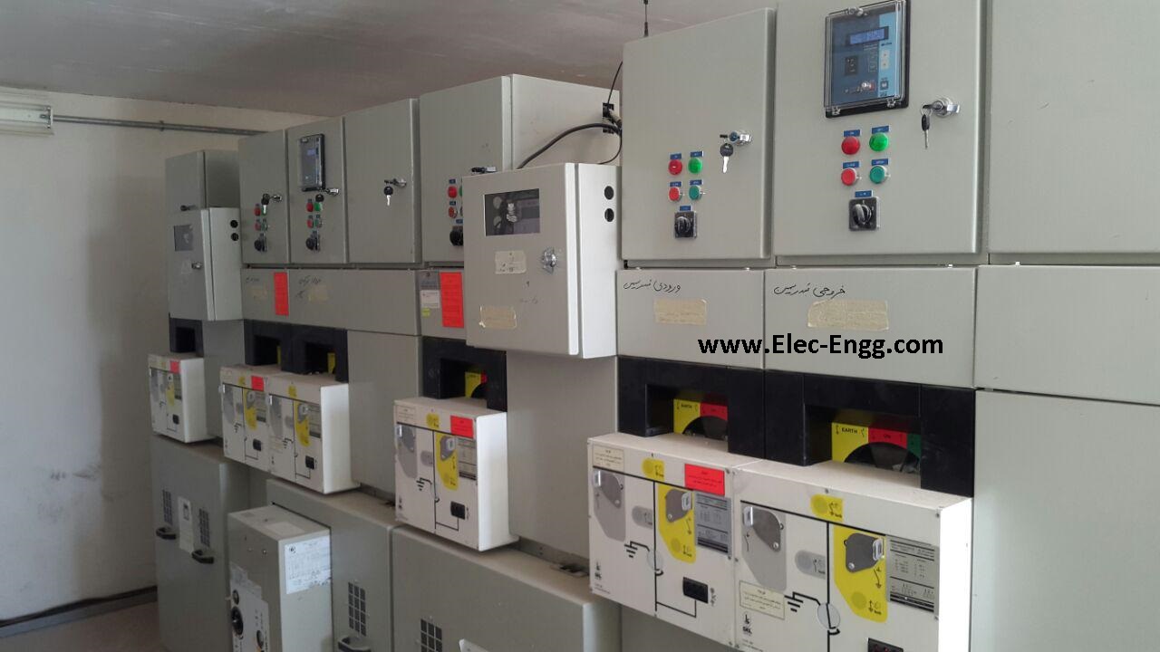
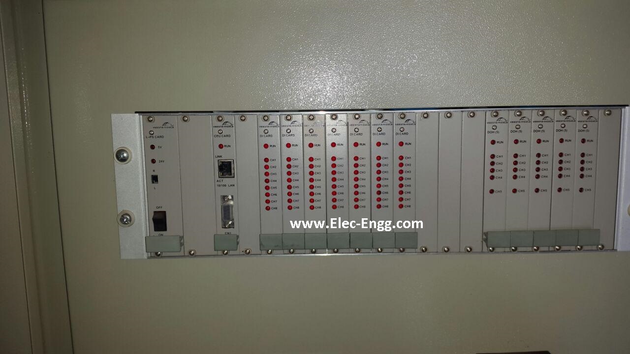
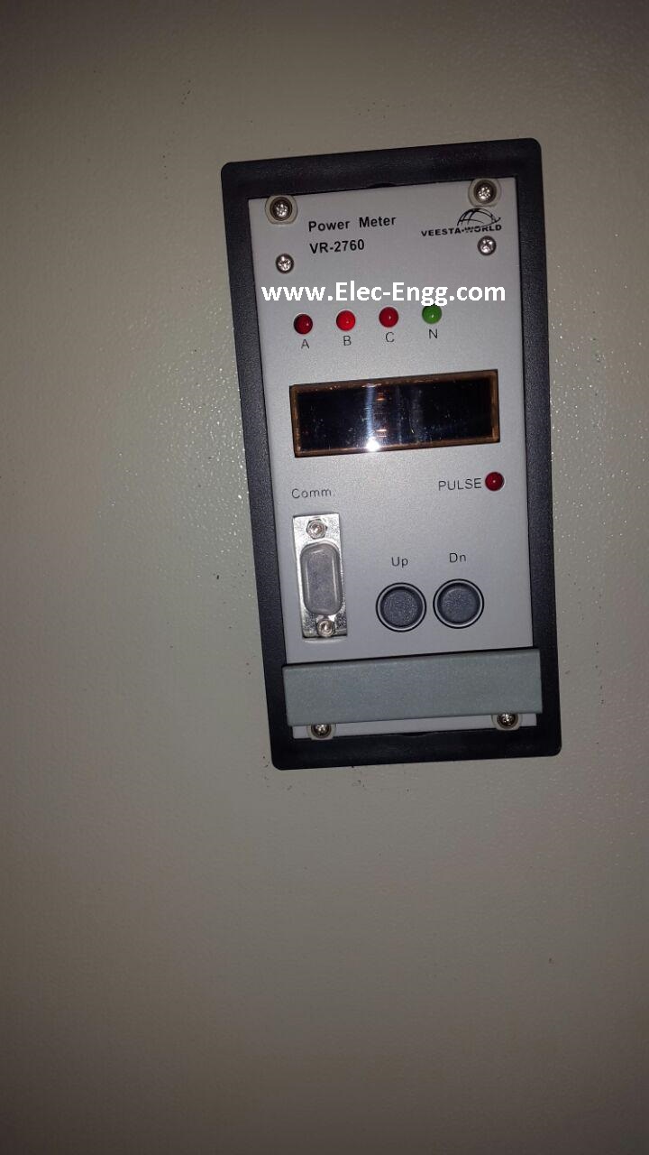
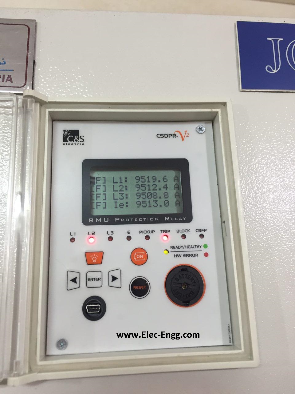
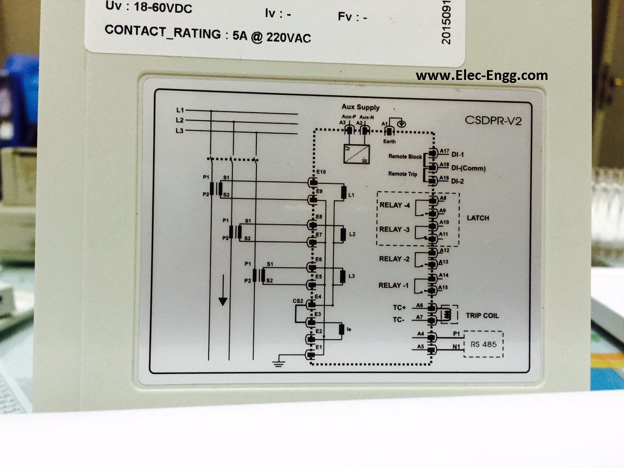
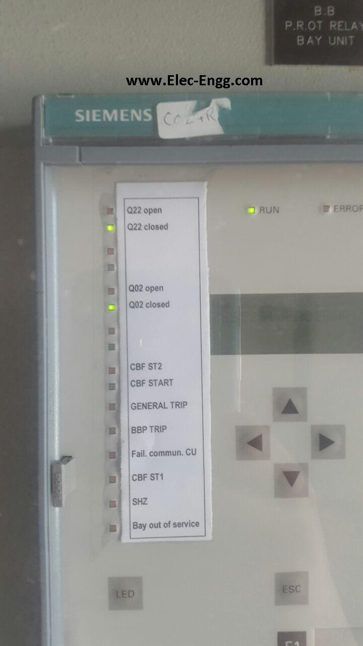
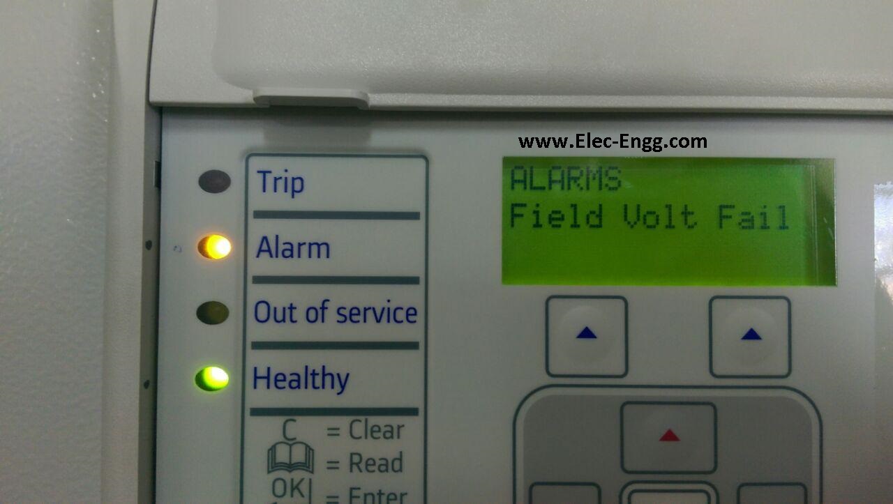
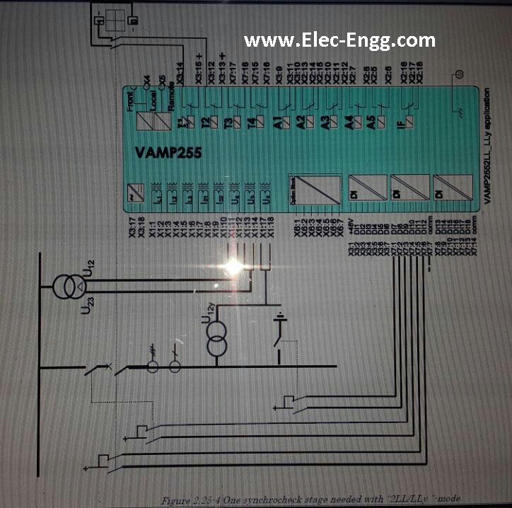
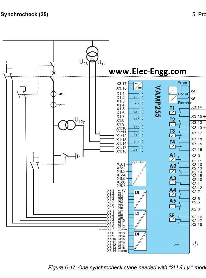
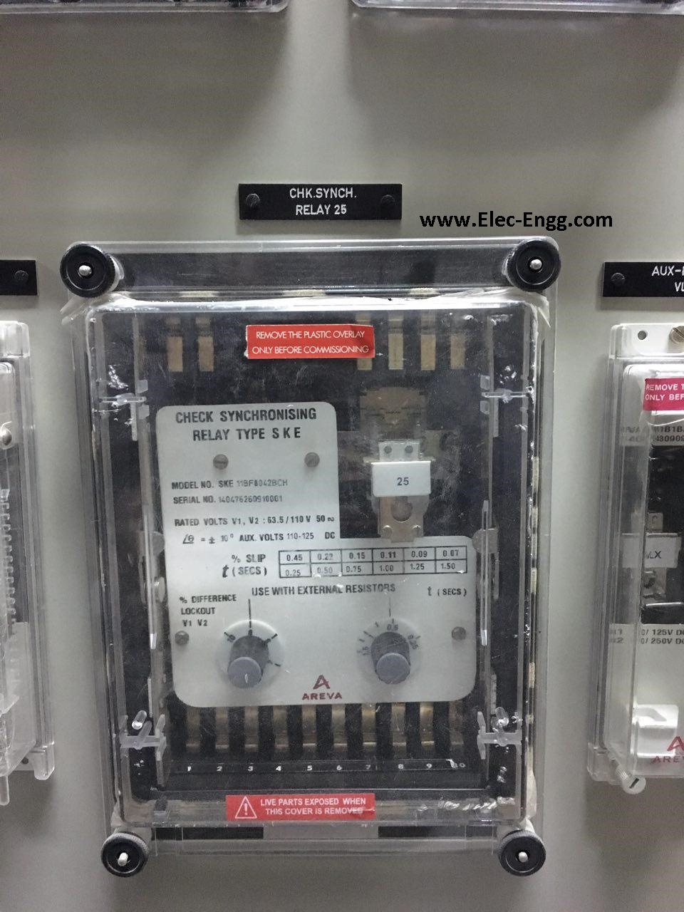
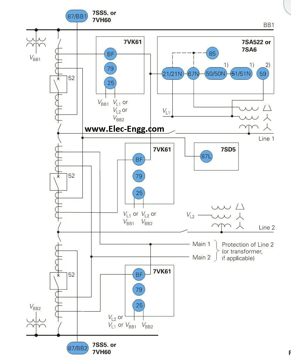
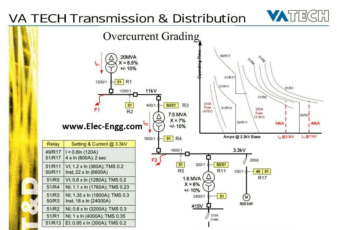
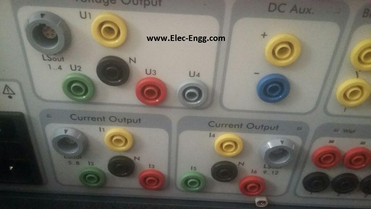
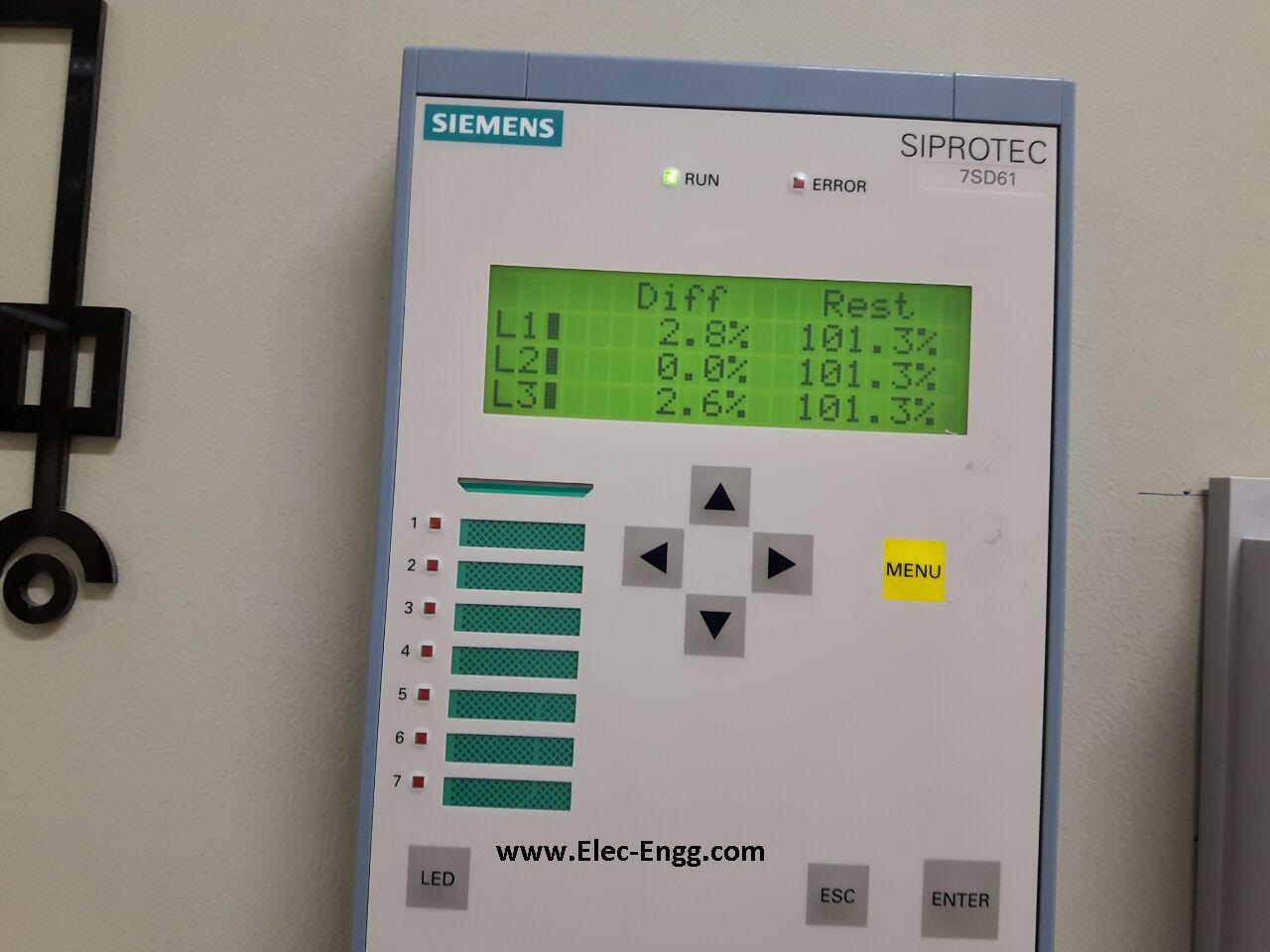

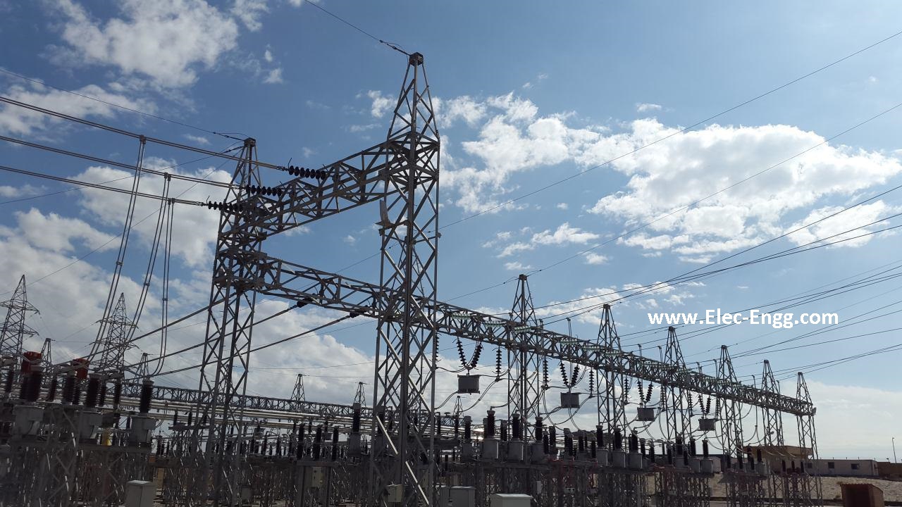
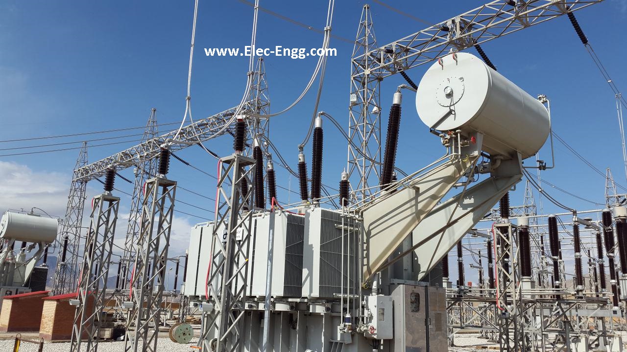
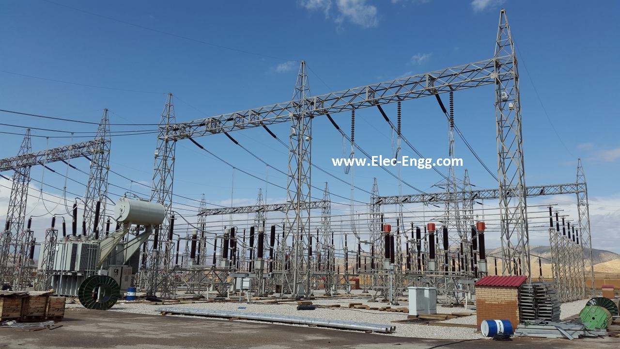
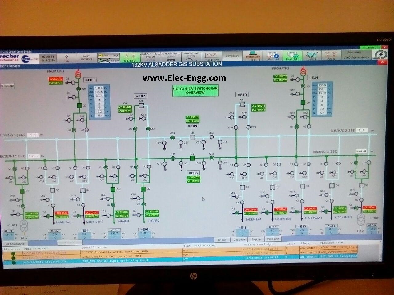
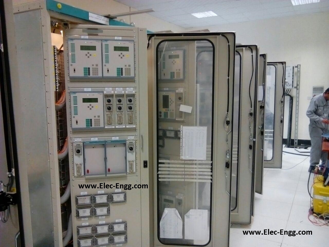
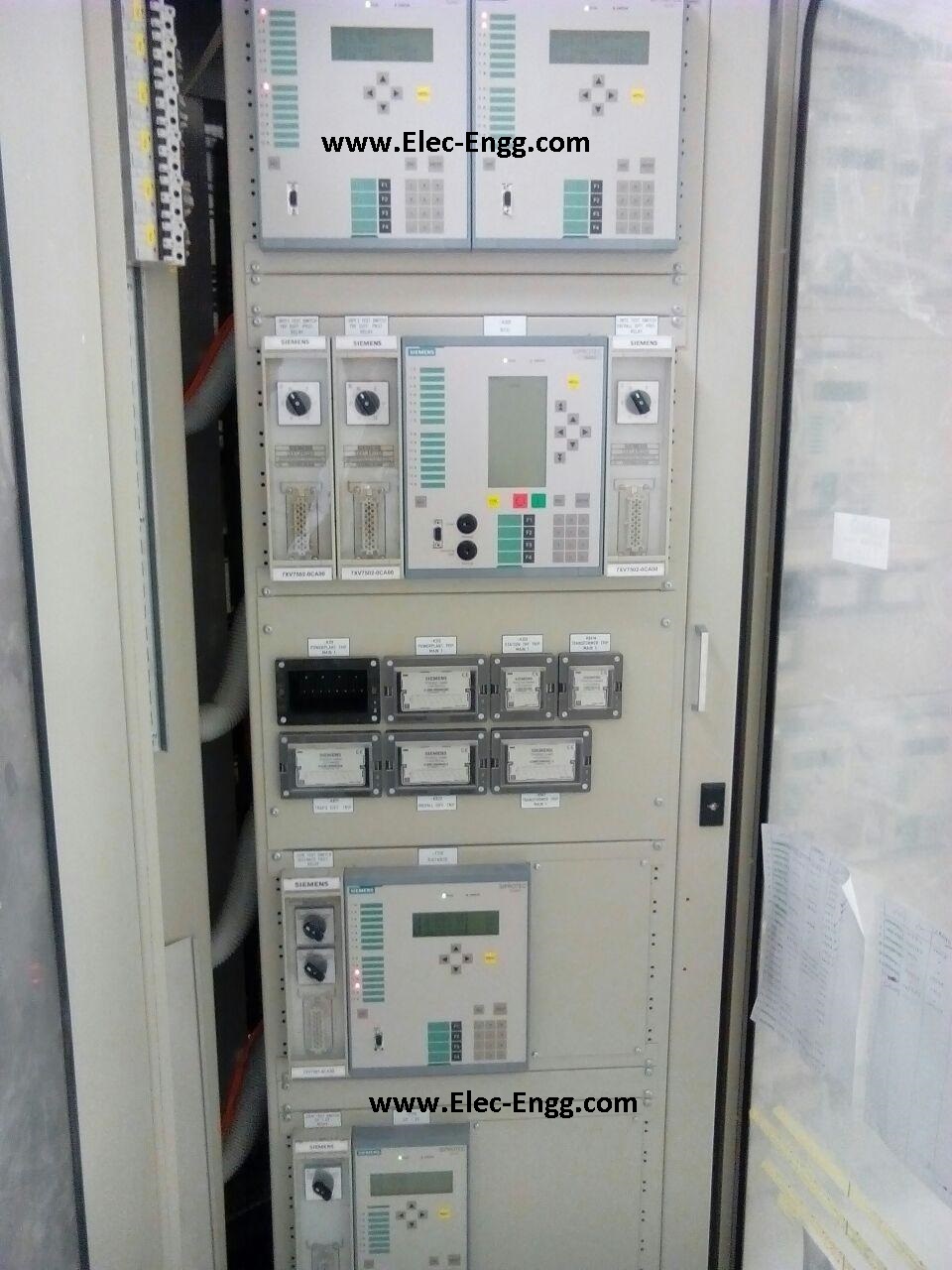
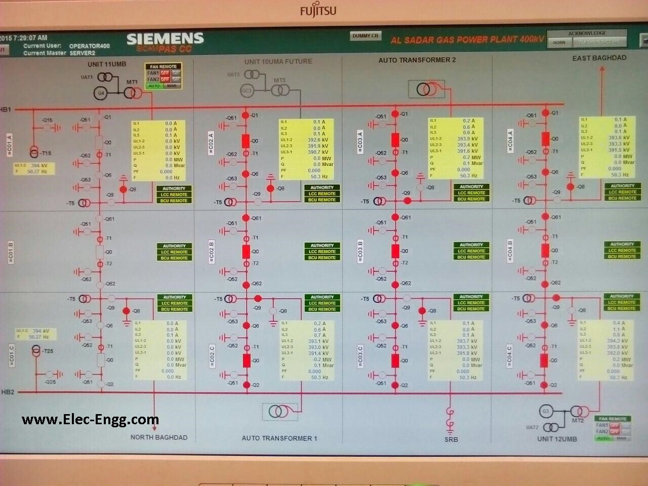
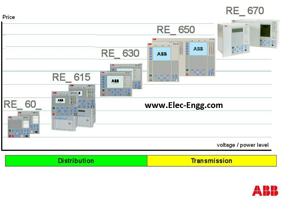
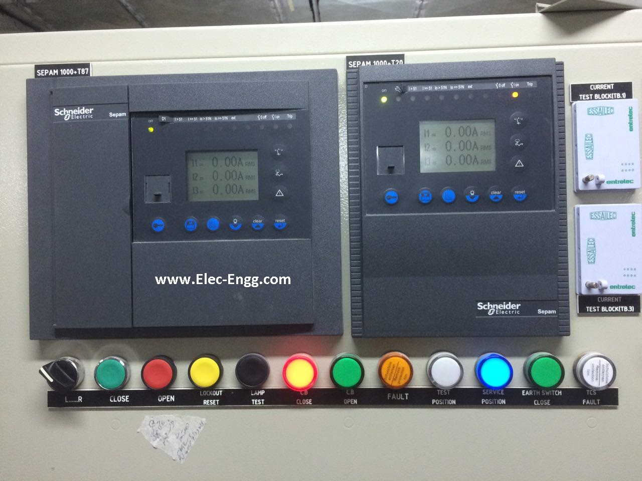
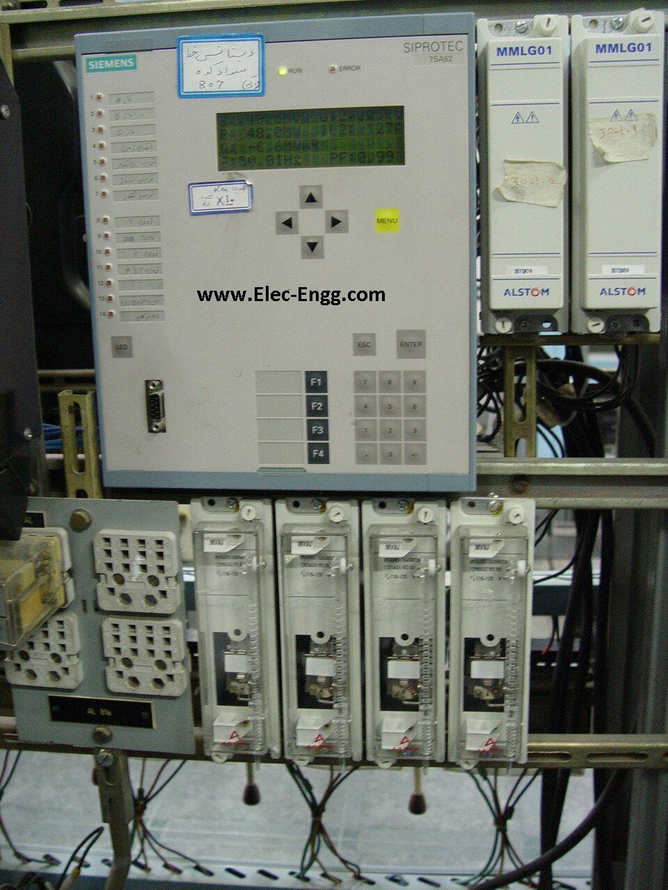
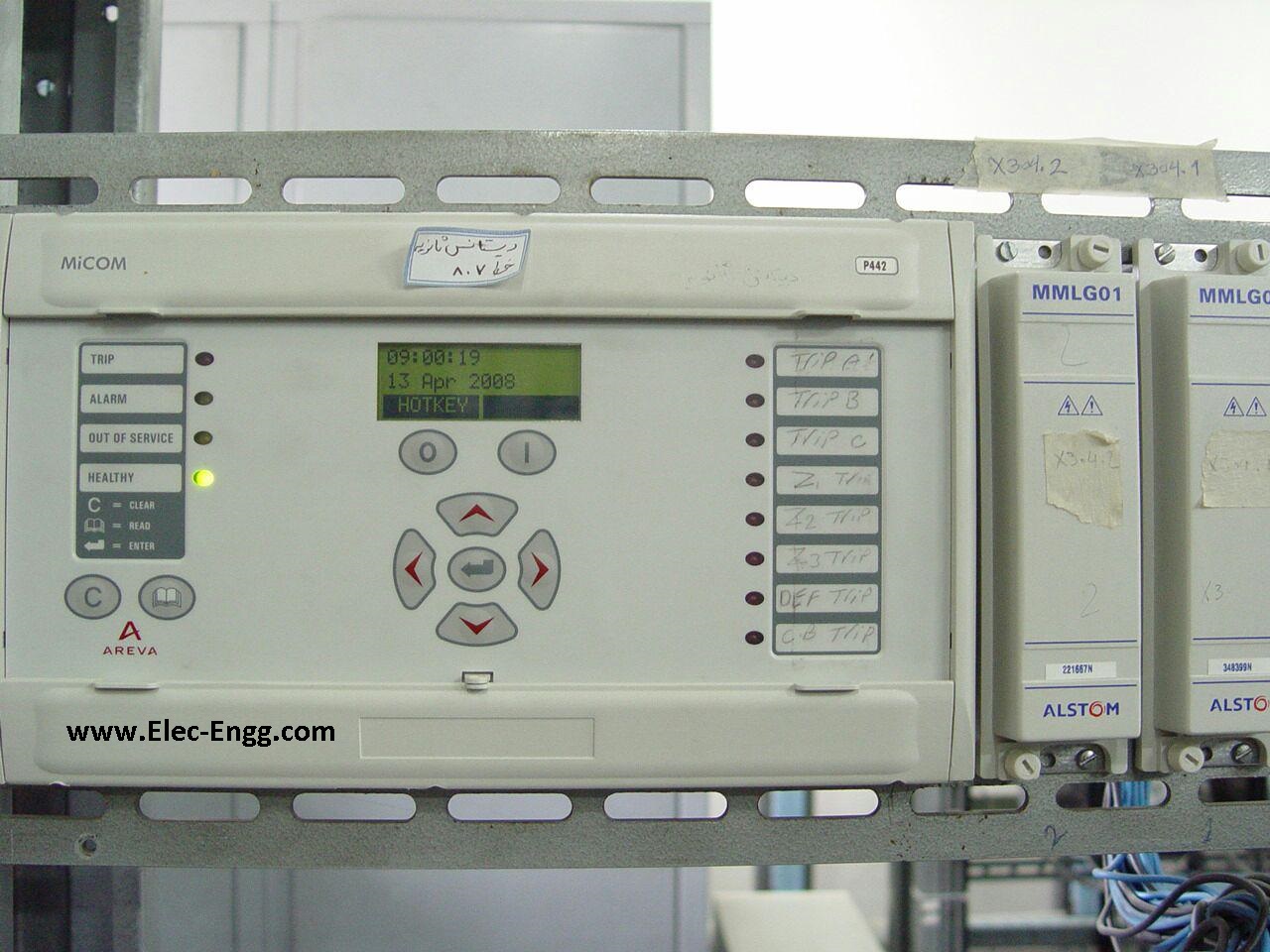

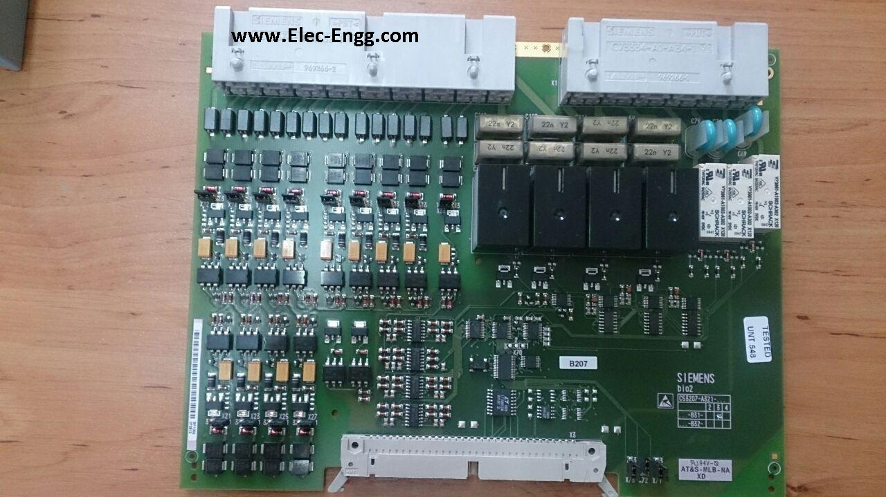
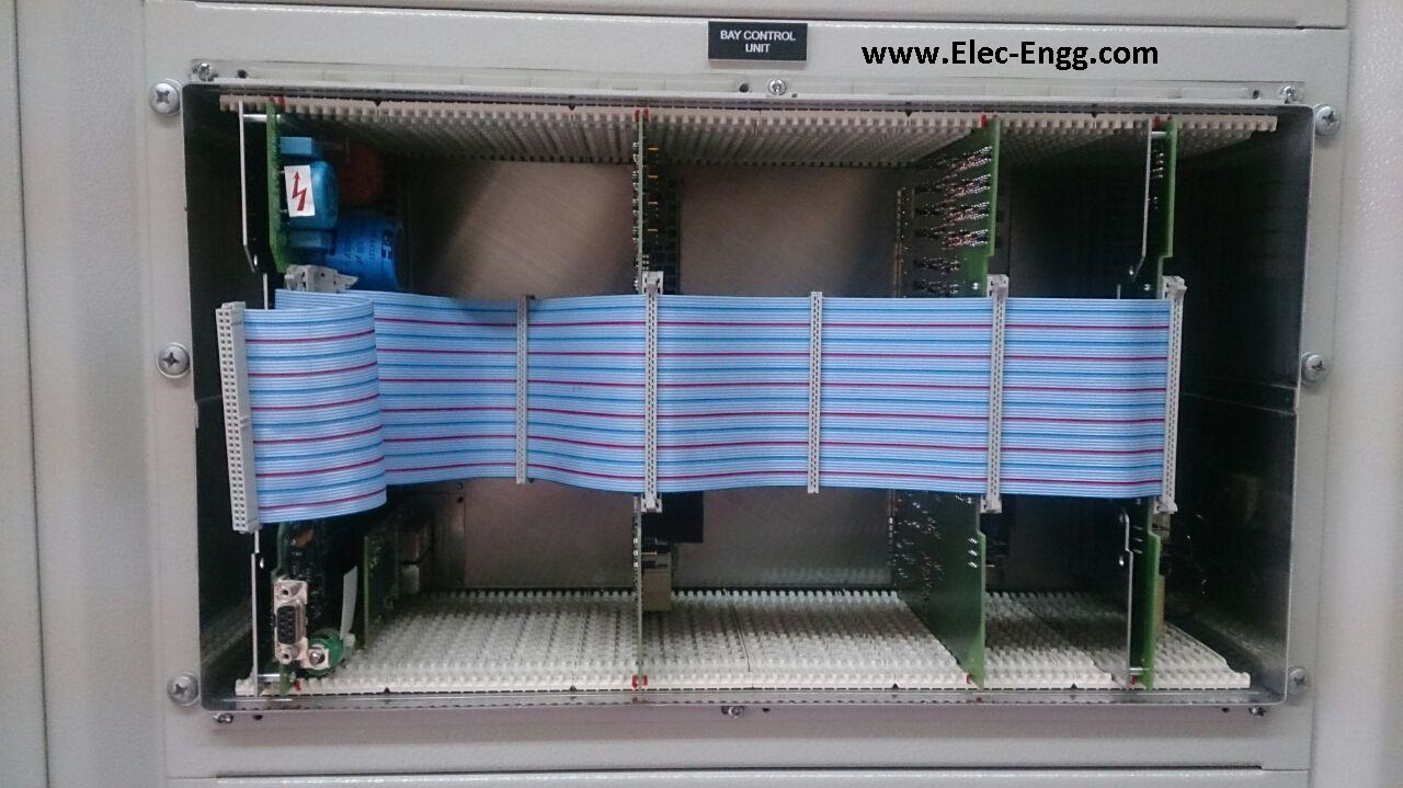
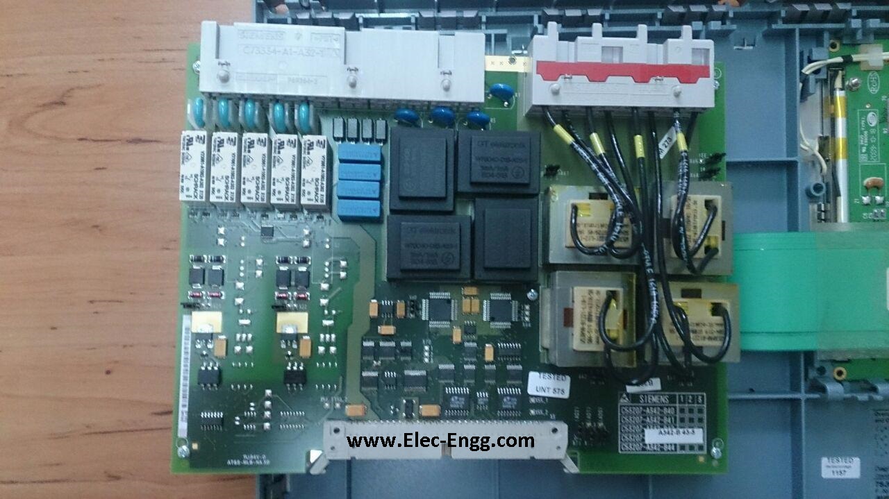

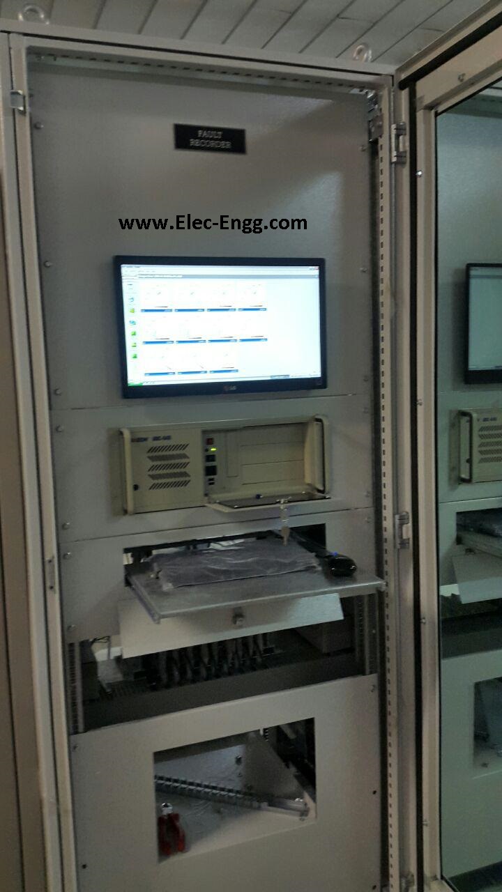
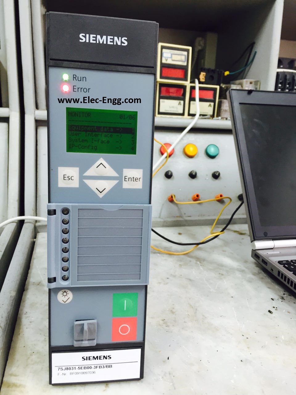
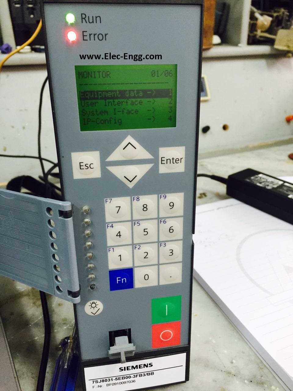
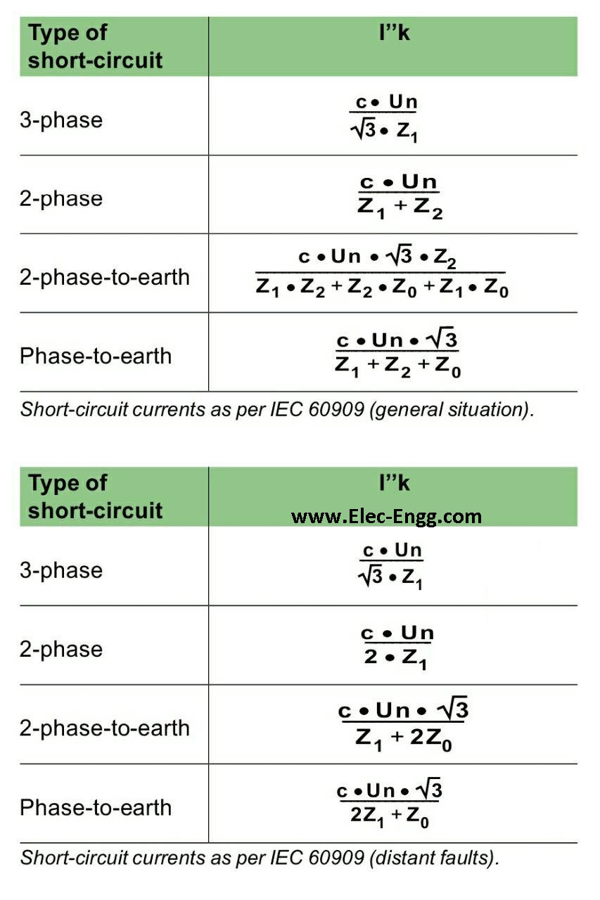
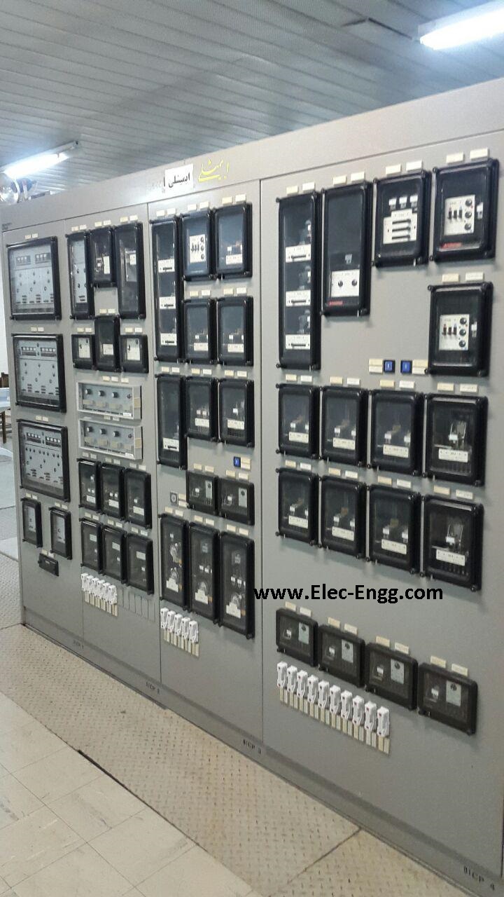
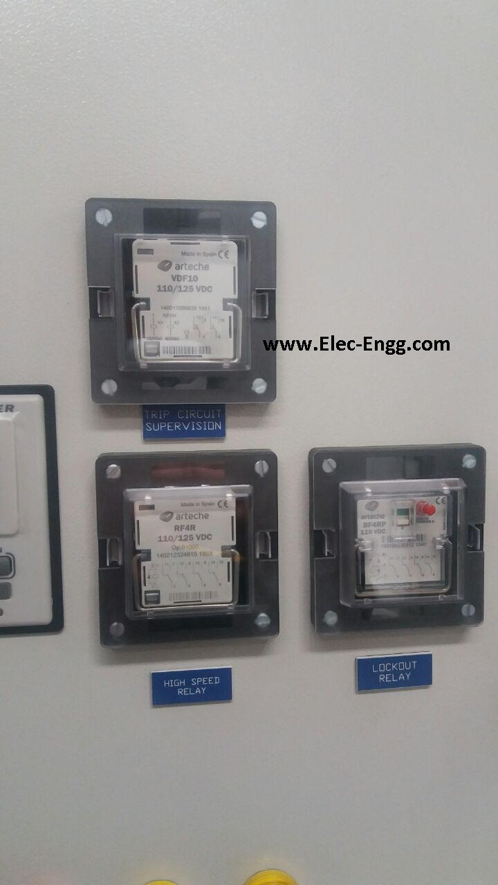
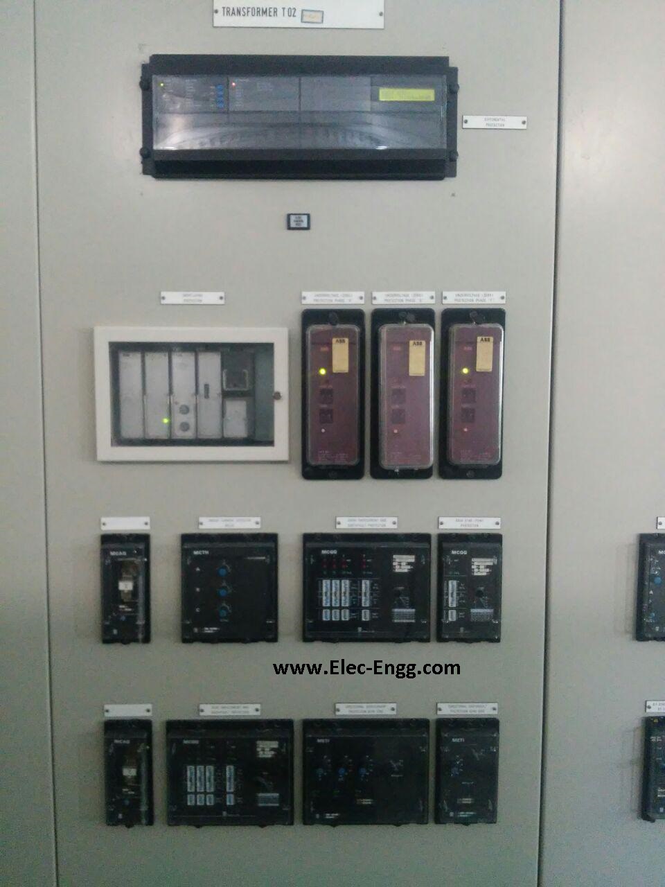
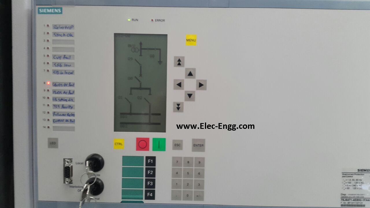
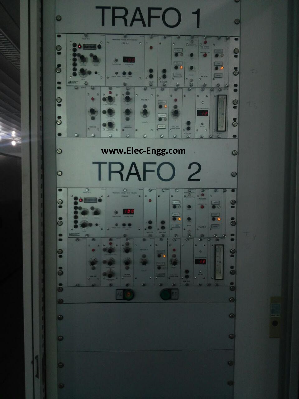
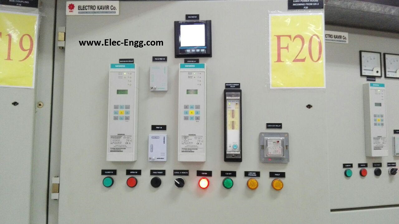
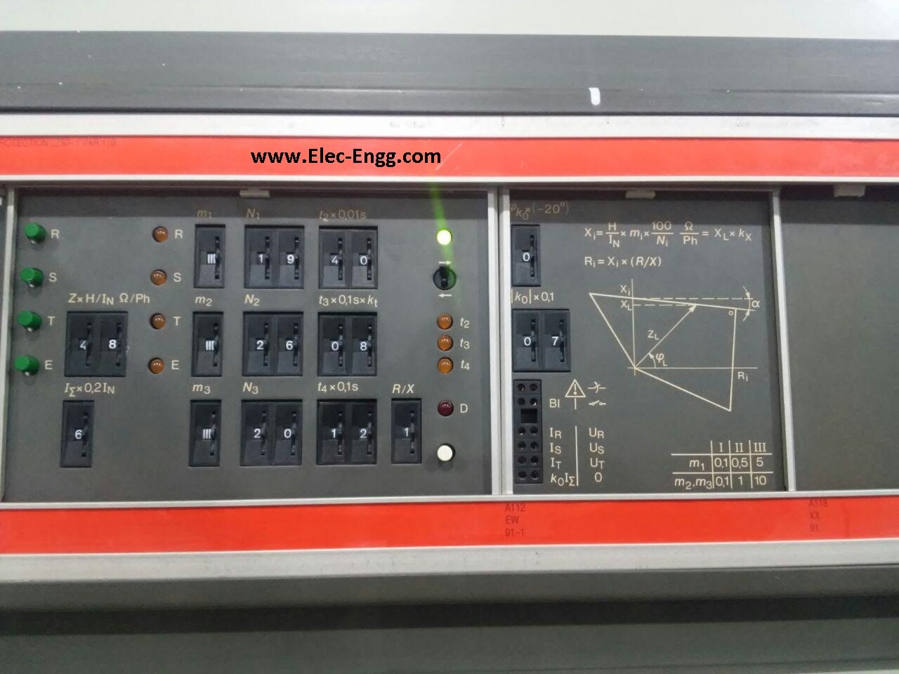
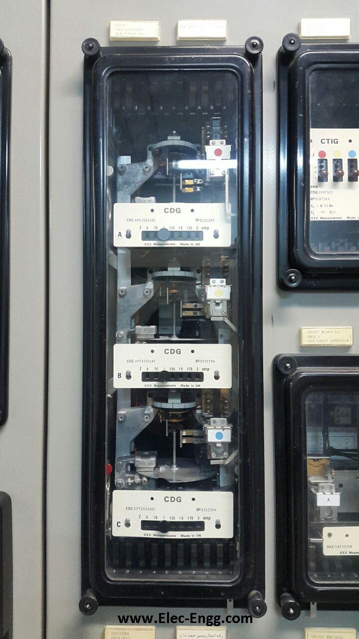
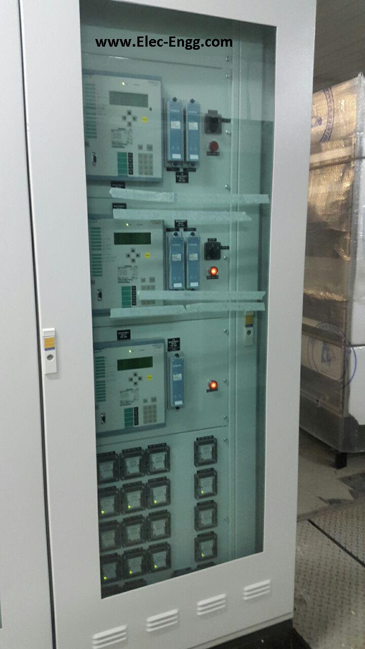
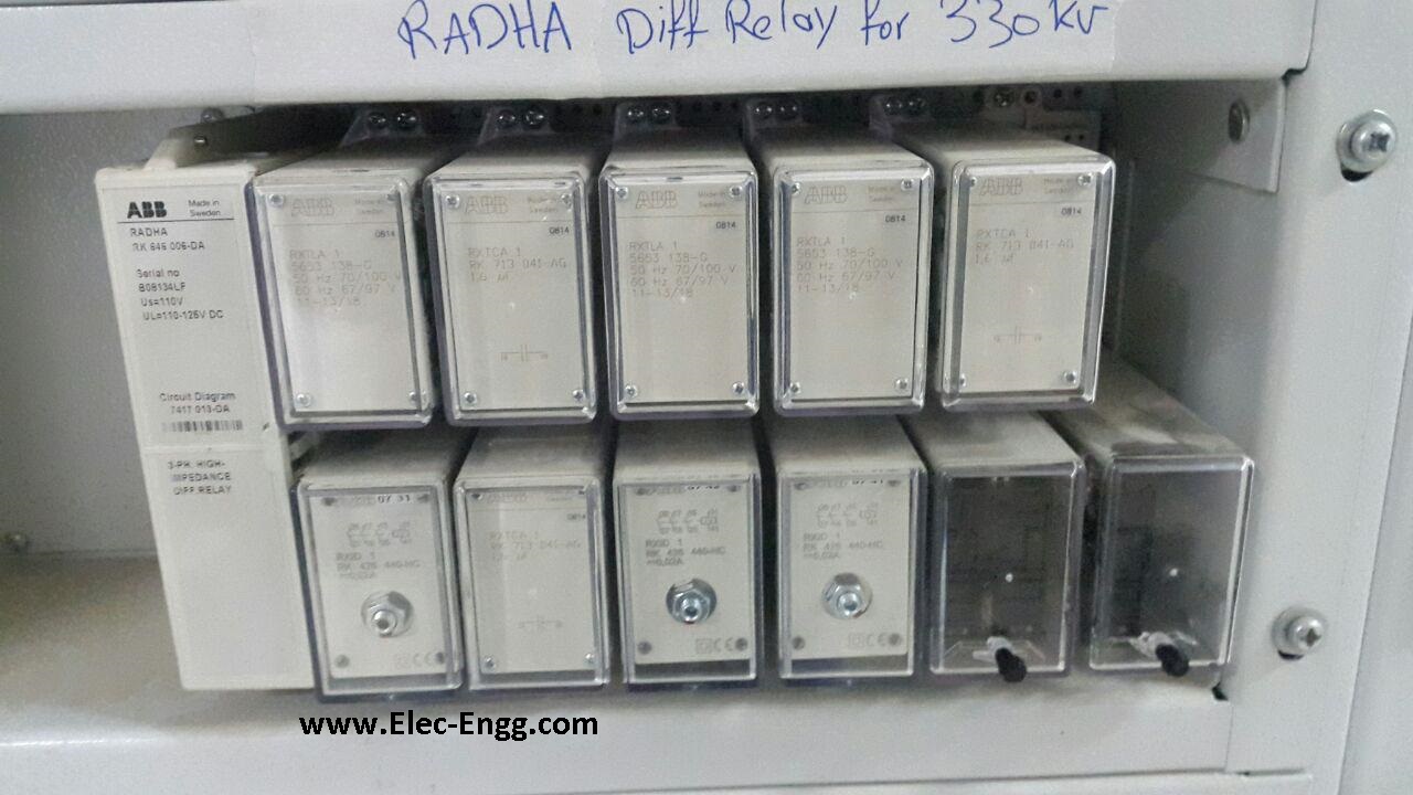
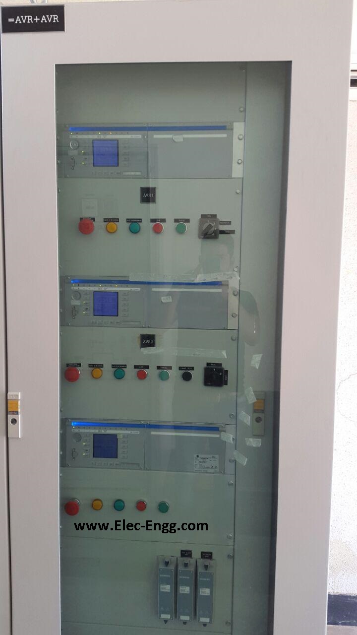
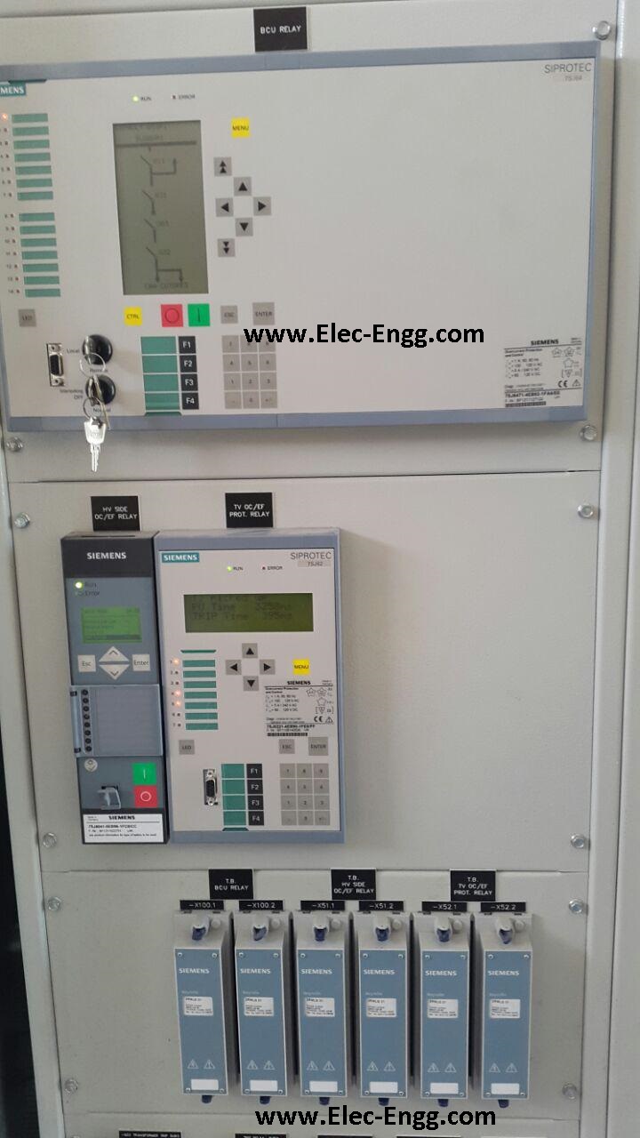
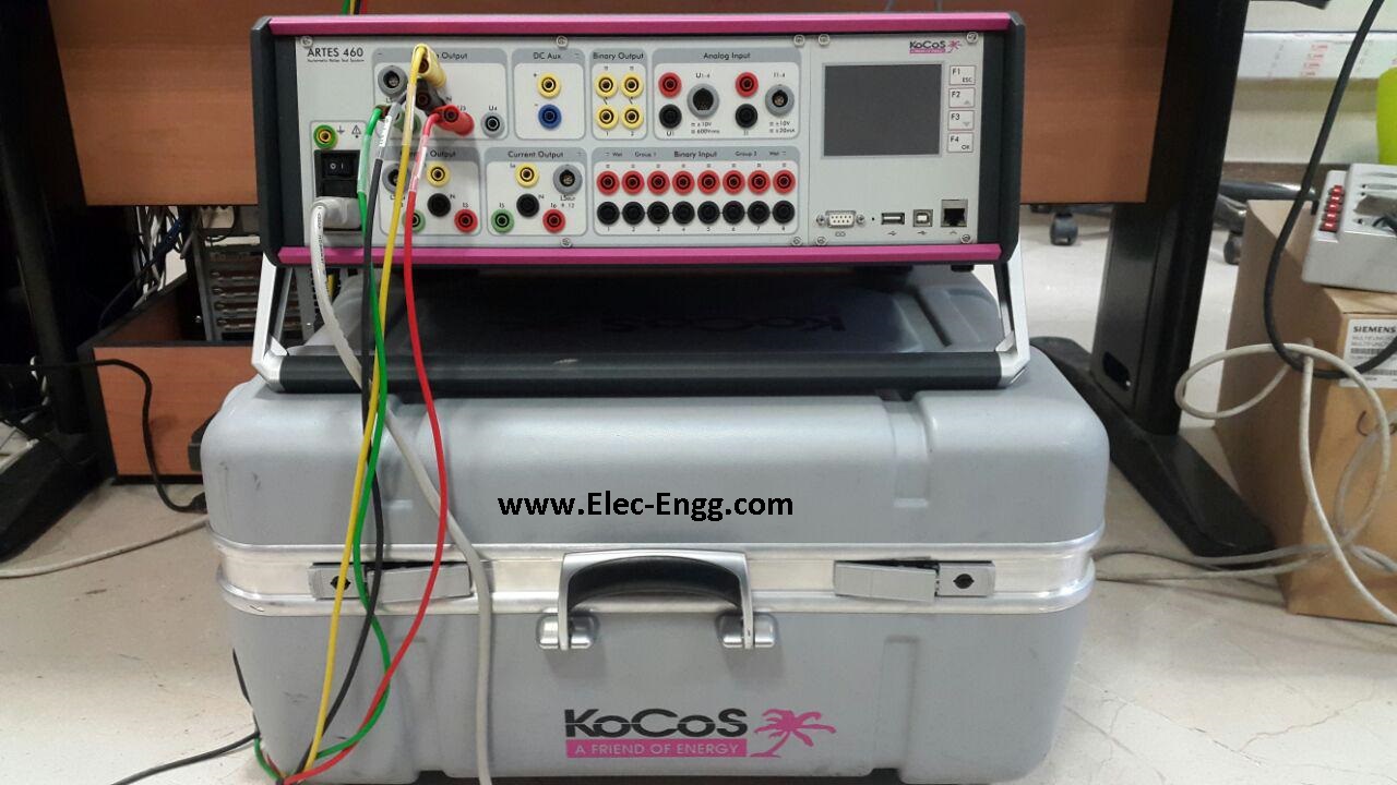
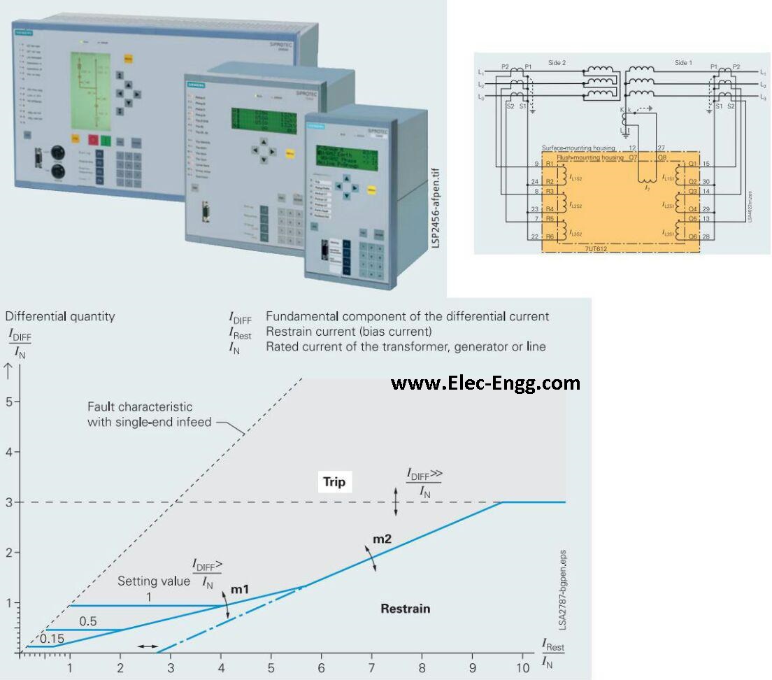

In the DIGSI 4 Manager first, you must open a device (offline or online). Afterward, a new window appears.
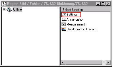
first view after opening a device parameter set
Click on the icon Settings. Now all folders of the domain Settings will appear. Click on the CFC chart and you will see the already existent CFC charts. Different devices have different default CFC charts.

Folders in domain Settings
If you want to create a new chart go to the Insert menu in the menu bar of the window where you see the folder Settings. In the Insert menu is one option available called CFC chart. If you click on it a new CFC chart will appear in the right window. The computer will name it with the default name CFC1. The name can be changed by clicking with the right mouse button on the new chart and choosing the item object properties. There the name can be typed again. With double-clicking on the inserted chart, you can open this new chart. If you do not want to have already existent CFC charts you can simply delete them by the right mouse button and choose the deleted item or directly from the delete button on the PC keypad.

After insert of a new CFC chart
A simple example of the interlocking feature in SIPROTEC 4 devices is explained using the following sample application:
The circuit breaker (Q0) is only permitted to close when the disconnector (Q1) is closed and the ground switch (Q8) is opened.
Refer to the input/output matrix. In the group control device, the commands for the switching devices are indicated. Each command occupies two lines.
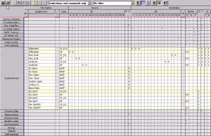
The commands in the input/output matrix
For example, the first line of the disconnector switch contains the command information which is routed to the output contacts. The second line is for the feedback signals which are derived via binary inputs.
Two binary inputs for feedback are required for double point indication i.e. if:
Controls without feedback can also be used, in this case, interlocking will not be possible. For interlocking, the feedback signals are the most important information. In this example, the interlocking must check the status of the disconnector (Q1) and the ground switch (Q8) before releasing a close command to the circuit breaker Q0. In picture 2 the CFC chart is shown. The status of the disconnector and ground switch is decoded with DI_TO_BOOL gates.
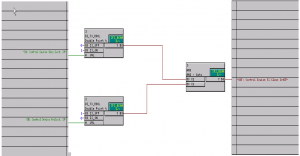
application of interlocking in CFC
The first DI_TO_BOOL gate decodes the closed position of the disconnector switch (Q1). The 2nd DI_TO_BOOL gate decodes the open position of the ground switch (Q8). If both these conditions are valid, the AND gate will generate the signal for releasing the
circuit breaker close command. The default settings already contain signals for interlocking (internal single point annunciations, see picture 1). For user-defined signals, these must first be created in the I/O matrix and routed to source CFC. Otherwise, these will not be available for selection later.
Ultimately the interlocking condition of the circuit breaker command must be allocated to the release signal derived with the logic. In the input/output matrix you have to click with the right mouse button on the circuit breaker and choose the object properties-item. The release signal Control Device 52 Close is responsible for the switching ON the circuit breaker.
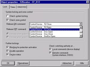
Object properties of the circuit breaker
For the control functions such as circuit breaker OFF or other devices, the same procedure must be carried out with the relevant interlocking conditions. The default settings of SIPROTEC 4 devices always contain a CFC chart with standard interlocking functions.
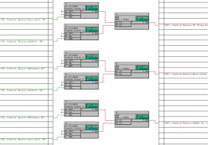
Extended CFC chart for interlocking of several switching devices

SIPROTEC 5 and DIGSI 5 Training
By: Dr. Saeed Roostaee
Training can take place at your company.
Thirty hours of training will be provided for the SIPROTEC, DIGSI, and IEC 61850 configuration.
For more information and reservation, please contact us.
The link to know details of this course: https://elec-engg.com/digsi-5-training/

Fundamental Principles and Requirements of Protection Systems
The purpose of this paper is to provide as clear a statement as possible of the functionality that Power System Protection has to fulfill to be considered ‘fit for purpose, and the requirements that this places on the concepts, design, components, and circuitry of protection systems. The statement of functionality is made in such a way as to form the basis of concepts and designs irrespective of the particular technology or combination of technologies used for its delivery. The Electrical Protection of power systems is an essential and critical function. The level of dependability and security required is the highest of any of the secondary circuit functions used in substations. The requirements are stated in a way that is independent of the technology used, to avoid restricting the development of new technology or applications. This approach is in the spirit of IEC 61850 in providing base rules and a framework for developing solutions without restricting the development of new solutions and improved functionality. The content includes key objectives of protection, basic principles applying to any scheme, all of the components involved (not just the relays), primary and backup principles (Remote BU and Local BU), and their implications. It deals with the requirements of secondary isolations of individual schemes required to permit safe work on a scheme while the remainder of the substation is in service, and with the requirements for simulated functional proving of protection schemes, again in a live substation. Segregation principles are also covered.
There are two aspects to the functional requirements:
Protection is a specialized discipline and requires people qualified or appropriately trained and competent in the discipline to carry out the various protection functions such as protection planning, system analysis, design and specification of relay systems, circuit design, relay settings, testing, installation, and commissioning.
Calculation of Loadability Limits of Modern Numerical Relays
Conventional calculation of load-ability limits of distance relays for different characteristics, such as Mho and Lenz, is based on determining the minimum permissible load impedance which is equivalent to maximum load current so that it does not encroach on the last forward zone reach of distance relay with a safety factor. In this paper it is shown that this philosophy, which is still used in some utilities for the calculation of relay load limit (RLL), does not apply to modern numerical relays due to utilizing the following elements for EHV transmission lines:
The functionality of LE is to block the relay under normal loading conditions as long as the load impedance is within the LE characteristic. Its characteristic consists of a circle cut by straight lines which represents the load angle. The radius of the circle represents the magnitude of minimum load impedance. Bearing in mind that LE responds only to balancing positive current, it is shown that LE characteristic does not need to grade with any forward zones as long as the maximum load angle is less than the line angle with sufficient margin.
The main objective of PSB is to block the operation of phase distance elements for stable swing. Its characteristic consists of two blinders or circles, one inner and one outer. The inner blinder/circle should encompass the outermost zone of phase distance protection that has been selected for blocking. The outer blinder/circle should be set so that the closest minimum load impedance locus is outside the outer blinder/circle characteristic for all loading conditions.
In this paper, it is shown that the load-ability limit of distance relays of numerical relays should be calculated based on the outer blinder/circle characteristics of PSB rather than the conventional method of the last forward zone, otherwise the functionality of PSB will be ineffective and relay may trip on stable swings. With this concept mathematical equations for the calculation of RLL are developed for two cases, one with a blinder and one with circular characteristics for PSB. In addition to impedance relays, a methodology for the calculation of RLL for current differential and overcurrent protection of new numerical relays is given. Finally, the results of an analysis of system disturbances that have occurred under normal system loading conditions due to wrong relay settings, design errors, relay failures, and human errors during testing are discussed. It will be shown how these disturbances could have been prevented if the correct design philosophy and test procedures had been implemented.
Download full papers at the end of this page ![]()
An Overview of D.C Traction Protection Systems
DC electrical traction systems consist of fixed components that enable power to be supplied to trains and trams for their traction and auxiliary operations. The purpose of the system is to supply electric power to rolling stock for traction and auxiliaries. It may also accept power back to the network when regenerated through breaking by the train or tram. The electrical interface is the interaction of the traction supply with vehicle-based systems and components. Key factors that influence the effect on the DC protection system are:
This paper describes the DC protection system on the traction substation and the limitations and implications of the traction system.
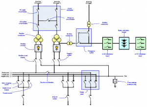
The Digital Substation – Principles, Functions, and Benefits
The IEC 61850 standard for Communication Networks and Systems for Utility Automation allows utilities to consider new designs for substations applicable for both new substations and refurbishments. The levels of functional integration and flexibility of communications-based solutions bring significant advantages in costs in all stages of a project. This integration affects not only the design of the substation but almost every component and/or system in it such as protection, monitoring, and control by replacing the hardwired interfaces with communication links. Furthermore, the design of the high voltage installations can be reconsidered regarding the number and the location of switchgear components necessary to perform the primary function of a substation in a high voltage network. The use of highspeed
peer-to-peer communications using Generic Substation Event (GSE) messages and sampled values from non-conventional or conventional sensors allows the development of distributed applications. In addition, the use of optical local area networks leads in the direction of copper-less substations.
The paper focuses on the definitions of the digital substation communication busses such as the station bus for the communication at the station level and between bays as well as the process bus for the communication between the high voltage process and components interacting with it. It analyses the substation communications architectures in substations with full implementation of IEC 61850, i.e. with station and process bus.
The different types of devices required for digital substations are described. Merging units that provide the interface between the current and voltage sensors and the intelligent electronic devices at the equipment, bay, or substation level are described, as well as the distribution of signal and data processing functions between the different devices for both architectures, which are analyzed. Some specific substation applications based on GOOSE and Sampled Analogue Values are described later in the paper and demonstrate the advantages of the new technology. Improvements in functionality, combined with practical elimination of performance or safety issues are covered in the paper.
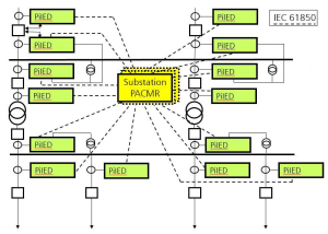
Download full papers at the end of this page ![]()
Impact of IEC61850 ed2 on Protection GOOSE
GOOSE itself brings many benefits that can be utilized for various protection signals, however, isolation and testing are critical considerations that are often seen as deficiencies in edition 1 (ed1) of the IEC61850 standard. A key driver for edition 2 (ed2) was to overcome these limitations. This paper looks at various isolation and test methods used for edition 1 and compares them to using edition 2. A major drawback of edition 1 was the inability to use online simulation. This limitation was not obvious and care is needed to ensure simulated or test messages are not used on a live system. This paper looks at the new simulation modes available in edition 2 which greatly improves this situation. The edition 2 simulation mode is quite powerful and this paper also looks at how this functionality can be used in a practical application. One of the stated objectives of edition 2 is to create solutions that can incorporate edition 1 relays. This paper also looks at the practicality of doing this.
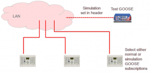
Download full papers at the end of this page ![]()
Case Study: Implementation of IEC61850 in Generator and Transformer Protection System in NSW Power Stations
Reliability, Efficiency, and Safety are the key objectives of any modern power system, and these can be achieved by the implementation of fully automated systems. The IEC61850 standard has revolutionized the automation process by standardizing system specifications, configuration language, naming convention, communication protocol, and conformance testing. The use of IEC61850 compliant devices can simplify the engineering design process, increase flexibility, and reduce engineering costs. To operate and maintain IEC61850-based systems, plant engineers must acquire knowledge about communication protocols, computer networks, classes, objects, etc. In New South Wales (NSW), the protection systems of the large turbo-generators (660MW units and above) and associated generator transformers have reached the end of their operating life. Most NSW generating companies have already implemented a program for replacing these generator and generator transformer protection systems. The new protection systems used IEC61850 compliant protection relays with an optical, peer-to-peer communication messaging system known as “GOOSE”. Being a protection retrofitting project to existing generating units, there were some difficult choices and design considerations in selecting the levels of IEC61850 implementation to these new protection systems. This paper looks at the extent of IEC61850 implementation in these retrofitted generator and generator transformer protection systems in NSW. It also provides a discussion on the impacts of the IEC61850 system on the operation and maintenance of these protection systems and possible future improvements.
COMTRADE Analysis to Visualize Protection Operations
This paper discusses methods of analyzing waveform recordings from numerical relays to diagnose power system events and confirm relay operations. COMTRADE format recordings often only capture the physical analog and digital signals wired to the relay, while internal protection functions will use algorithms to manipulate these signals before determining a trip condition. With a basic understanding of the relay algorithms, the operating quantity can be derived from the recording and compared to an operating characteristic to verify settings and confirm relay operations.
Examples presented include analysis of harmonic content of inrush waveforms, trip locus of differential and impedance-based characteristics, high impedance-based protection trips, and fault finding installation and application issues.
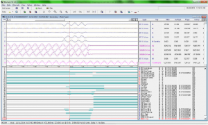
Download full papers at the end of this page ![]()
Verification of Distance Protection Scheme of double circuit transmission line using power disturbance records
The Channel Island Power Station is the major generation source for the Darwin-Katherine region. Power delivery to the greater Darwin region is via two 132kV overhead lines to Hudson Creek Substation which are installed on separate towers sharing a common corridor. Figure 1 below is a simplified network diagram used in the model to study the impacts of the influencing factors including source impedance ratio, load-flow, mutual coupling, fault impedance, single-pole tripping, auto reclosing, and current reversal. The first part of this paper describes the selection of the proposed replacement system. The second part describes the evaluation of the combined effects of the influencing factors and the last part describes verification using available power system disturbance records and the test scenarios generated by RelaySimTest.
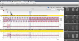
RelaySim Test Scenarios for verification of the protection
Cygnus Atratus, and How it Causes Problems
Protection systems deal with two different types of faults, ones we expect and faults that are unique and had not been considered. This paper describes black swan events, and how we as protection people should make our system black swan tolerant. It looks at several events, not all within the power industry, and describes how different thinking may have prevented incidents from occurring. It describes the effect of outliers on fault analysis and black swan recognition. The author has been involved in a black swan style theory for many years. As a book by Nassim Nicholas Taleb has created the terms used nowadays, those terms are used throughout this paper.
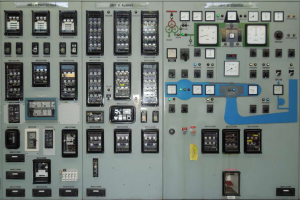
Download full papers at the end of this page ![]()
Application of the Line Differential Protection Scheme for Radial Transmission Lines
Modern communication networks have dramatically increased the implementation of the line differential scheme as one or both primary protection for transmission lines. The transmission network usually meshes which also provides fault current contribution from both ends of the line. Considering the ongoing need to reduce CAPEX investment, it is expected that the supply to specific loads, for instance, mining in rural zones of Australia, the transmission network could be expanded radially with single or double circuit applications. In a radial system, in the event of a fault, fault current contribution is drawn mainly from the source side. This scenario could potentially create issues with the operation of supervisory elements of the line differential relay at the remote end. This paper reviews this specific application with particular attention to solutions that balance the need for security, speed, and dependability of the line differential protection scheme.
Modeling and Testing of High Impedance Differential Scheme Using Numerical Relays
A high impedance (HiZ) differential protection scheme has been used for busbar protection over many decades. The basic idea used in this scheme avoids problems related to CT saturation through faults by connecting high impedance in series with the operating relay. Relay with high impedance burden and CT’s are connected in parallel to force the false differential currents (caused by CT saturation) to go through the saturated CT’s rather than through the relay. As long as the voltage across the summation point required to operate the relay is higher (with a certain margin) than the
maximum voltage developed during maximum through fault, the scheme provides adequate security. This requirement is usually easy to satisfy and very few utilities ever had an issue with scheme security caused by CT saturation. On the other hand, tripping for internal faults relies on CTs’ ability to provide enough secondary current through a very high impedance of the relay branch during an internal fault. Under an internal fault condition, at least one CT with primary current drives secondary current into high resistance of the relay branch. This creates a high voltage across CT terminals. This voltage usually exceeds the knee point voltage of the CT and eventually saturates (from the second terminal side) other CTs connected into a high impedance scheme. The low impedance of saturated CTs reduces the burden on source CTs but also allows spill current to flow into saturated CT’s not into the relay. As a consequence, in steady-state, the current through the relay flows only during short periods when the voltage across the summation point is below the knee point voltage of CT with the lowest knee point voltage – i.e. periods before the smallest CT saturates. Early schemes had been implemented using high (usually nonlinear) impedance voltage relays. These relays were extremely fast because the very sensitive operating coil in these relays (usually 5mA – 10mA) would operate almost instantaneously when voltage increases over the knee point of internal nonlinear resistors used to set the voltage pickup. Over time, the voltage relays had been replaced with electromechanical (EM) instantaneous overcurrent relays (usually armature type) and burden resistors. More recently, EM relays have been replaced with solid-state and numerical overcurrent relays. The general understanding is that the HiZ scheme performance is expected to remain satisfactory as long as few original design “rules of thumb” are met. At the same time requirements for smaller CT have been intensified due to switchgear size reduction. This paper presents methods and findings of modeling and simulation of an HiZ differential scheme. Relay performance under internal fault conditions was studied. Conclusions and some recommendations for scheme improvements based on these findings are presented.
Download full papers at the end of this page ![]()
New Design of Distance Protection for Smart Grid Applications
Smart grids of the future will have new challenging requirements for the protection elements regarding selectivity and dependability. The load flow will be increasing, the magnitude and direction of load flow may frequently be changing, and even the network topology will be more complex than today. This paper presents a new design of distance protection that perfectly fits the requirements of the smart grid of the future.
The impedance measurement is based on the calculation of the load compensated fault reactance X and from the line, resistance separated fault resistance. This method is applied for the phase to the ground as well as phase-to-phase faults. Separation of the fault resistance improves the accuracy of the impedance calculation. The method reduces the negative influence of fault resistance during high load flow and minimizes the risk of the wrong pickup during high load conditions. Once a fault is detected, it is very crucial to select the faulted loop to calculate the impedance to the fault. For complicated faults in the complex network of a smart grid, this can be a challenging task with a certain risk of non-selective fault clearance. In the past, the loop selection was done by a so-called decision tree, in which several criteria were applied sequentially to find the faulted loop. Thereby, only the result from one criterion selects the faulted loop. The new approach is different. Several criteria are based on magnitudes of voltages and currents, changes in voltages and currents, symmetrical components, or impedances are applied in parallel. The results of every single criterion are weighted and combined to get a final result for the selection of the faulted loop. With this principle, the efficiency of the loop selection has been optimized to different network topologies by changing the weights of each criterion. The same principle is applied to the directional element. Multiple criteria based on actual voltages, memorized voltages, symmetrical components, or delta quantities are applied in parallel. The final result is obtained as a weighted combination of the result of every single criterion.
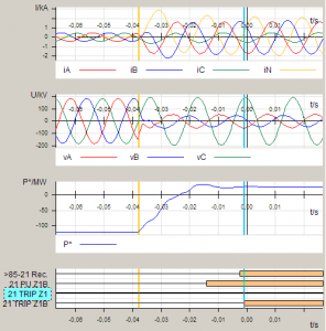
Communication Aided Protection Schemes and their Implementation and Testing with State-of-the-Art Technologies
Electrical power systems and the related protection and control systems evolve. Systems get extended, and the existing parts have to be adapted to the new configuration. While extending the primary system is more straightforward in most cases, the adaption of the protection system can be more challenging if the topology of the primary system is essentially changed. The adaption of protection settings is not sufficient to cope with such situations. New protection concepts or improved information exchange between protection relays may be required. This paper describes an electrical power system with five terminals that evolved and how recent technologies were applied for upgrading the protection system and how the testing of the system was performed.
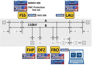
Download full papers at the end of this page ![]()
Implementation of Multi-Intertripping Protection Schemes in a Complex EHV Industrial Substation
This paper describes the design, installation, and commissioning of new numerical protection and control and inter-tripping schemes at an EHV substation. The substation supplies a critical and large industrial plant (paper mill). The connection consists of two radial 110 kV transmission lines connecting four 25 MVA, 110/6.6 kV transformers, two of which are dual wounds. Each transmission line is directly connected to a transformer. The 6.6 kV sides of the transformers are connected to different busbars via circuit breakers. For a fault on the 110 kV lines or the transformers, the remote end 110 kV circuit breaker and appropriate 6.6 kV circuit breakers must open.
This arrangement required complex inter-tripping schemes between the protection devices of the transformers within the substation and between the protection of the local substation and remote substations. The secondary work at the local and remote EHV substation included installing new 110 kV transmission line protection schemes, consisting of Main ‘A’ and Main ‘B’ new numerical relays for each line. This included the removal of existing inter-tripping schemes.
The project necessitated an innovative design, settings, and logic programming to be implemented on new relays. Existing secondary infrastructure including copper cables and intra-substation fibers of the single old protection scheme was utilized for the now duplicated transmission line protection. This involved the following.
Finally, the paper discusses how the implementation of the project involved innovative solutions so that new primary equipment and secondary copper cabling was not required while providing high system reliability and security
XML and UML – What They are and Why We Need to Know Them
The power system automation community is going through a period of transition from the world of hard-wired systems and proprietary configuration and analysis tools into the world of distributed IEC 61850 communications-based systems and object-oriented standards-based engineering and analysis tools. This requires the development of a new set of skills to help the specialists from our industry understand and use the new technology. The main goal of this paper is to introduce the Extensible Markup Language (XML) and the Unified Modeling Language (UML) to the protection and control community and focus on the UML diagrams and XML files used in the IEC 61850 standard and some IEEE standards related to protection and control to help the readers understand the diagrams and files included in or defined by the different standards.
Examples of the use of UML diagrams in IEC 61850 are given later in the paper.
Examples of the use of XML in the IEEE C37.239: IEEE Standard for Common Format for Event Data
Exchange (COMFEDE) standards are presented at the end of the paper.

Old Lessons – Re-learned
Over national holiday breaks, and weekends, especially during the spring and autumn, low loads and high proportional wind generation could combine and result in fault levels on the network dropping to unexpected values. In the event of a system fault, this could adversely affect the operation of protection schemes. If protection schemes do not detect faults the effects of system events will become more widespread leading to unnecessary damage to assets and power supply disruption. Looking at the operation of single-phase tripping schemes, this paper will discuss how the schemes work to clear a fault and the importance of ensuring tripping at all ends of the protected feeder with particular emphasis on Wind Farm fault supplying capability and protection scheme sensitivity looking at the various differential, distance and distance signal-aided line protection schemes. For transformer protection, we look at how basic relay settings are modified by zero-sequence filtering and ratio compensation leading to differing sensitivity.
Download full papers at the end of this page ![]()
330 kV downed conductor protection and successful operation
Line protection systems were replaced between Transgrid’s Upper Tumut Switching Station and Snowy Hydro’s Tumut 1 and Tumut 2 Power Stations. The risk of a downed conductor before synchronizing the line at the switching station was identified, and a protection system was designed to detect this failure. Traditional systems would not detect this unique event until a significant quantity of fault current was reached with a possible bush fire. The predicted event occurred less than a year after the protection was installed, and was correctly cleared with no extra plant or environmental damage. This paper examines the thought processes required to see the need, the need and implementation of the protection, and the resulting fault and protection operation.
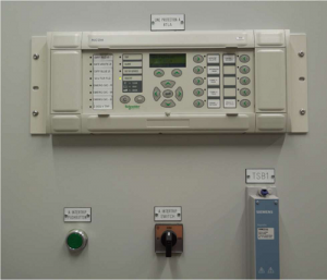
The Reality of Providing Energy in Australia: Bushfire Mitigation and the Benefits of Power Quality Monitoring Outside Substations
In Australia’s electricity supply history, utilities have grappled with some unique issues. Australian utilities are known for innovation, and the utility demands placed on manufacturers have been responsible for some of the greatest steps in switchgear development. As one of the largest interconnected networks in the world, distribution network service providers (DNSPs) in Australia face big issues presented by the unique geography and climate. One of the greatest causes for concern in the Australian Distribution community is the aspect of bushfire risk. Australia has a long history of bushfire disasters, but instead of the devastating events of February 2009, the impact of utilities has been burned into the Australian psyche. The resilience of Australia’s utilities and engineers prompts appropriate development to mitigate these risks, and this paper outlines some of the features available using one of the most common protective distribution switchgear devices: the automatic circuit recloser (ACR). ACRs humble beginnings as hydraulic devices in the mid-1900s have evolved greatly through the years through to semiconductor-controlled switches. These switches have proliferated across networks all over the globe, driven by the immediate reliability benefits and protection offered on a reasonable budget. Australia itself has had a fair share of manufacturers, and today there are thousands of NOJA Power reclosers in service providing reliability to customers. Driven by continuous requirements from utilities, these semiconductor-controlled reclosers have been greatly developed, and this paper presents some solutions implemented to combat the challenges of the Australian distribution network. Bushfire mitigation is at the forefront of development, and through the use of the NOJA Power RC10 control system, it is now possible to update and integrate bushfire mitigation strategies using commissioned NOJA Power assets, with a simple firmware update and a network integration strategy.
By using the onboard voltage and current sensing capabilities of these reclosers, the RC10 now can conduct complete power quality monitoring and reporting – a technology long bound to the granite yards of substations. This functionality is now available out on the feeders, using the same protection devices installed years ago, providing power quality feedback from the shores of the gold coast to Uluru. Enhancing Australian Protection System Testing through Real-Time Digital Simulations The modern power system is large and highly complex. At the same time, several new and potentially disruptive technologies can redefine the way the power system is designed, operated, and managed, changing long-existing network dynamics. Examples of these disruptive technologies include intermittent power generation (such as wind and large-scale solar PV farms), centralized energy storage, and distributed generation (DG). Meanwhile, computational power and sensing capacity is continuously increasing within the network. New generation network devices (including flexible alternating current transmission systems (FACTS) such as synchronous static compensators (STATCOMs), HVDC interconnections, multi-terminal dc networks, and dc grids) extend the available solutions but further complicate the optimal selection of technologies. This increased complexity also translates into requirements for more sophisticated and highly selective protection systems for faster fault detection and isolation, to minimize disruption and increase network availability. Improper settings or coordination among protection devices can lead to major network disruptions, as demonstrated in the 2003 North American Eastern Interconnection Blackout. Inadequate understanding of the power system and inadequate situational awareness are considered among the major causes of such failures. Recently, the aspect of grid resiliency has also attracted attention, in addition to the existing focus on reliability, efficiency, and cost-effectiveness. One of the main methods of demonstrating and verifying the performance of current and future power systems, thoroughly testing the design and operation of protection schemes, and experimenting with novel methods and approaches is through the use of real-time digital simulations. The concept of real-time digital simulations was initially introduced in 1969 by Dommel [3] and is based on the calculation of the system’s currents and voltages using the conductance matrix of an equivalent electrical network at a time smaller than the defined time-step [4]. The time step should be selected so that the real-time behavior of the network is accurately emulated and provides trustworthy results. Through real-time simulation, the behavior of the power system can be observed in real-time. At the same time, external hardware (e.g. digital controllers or protection relays) can be directly connected to the simulator enabling studies on the response of hardware and the response of the power system following any operation of the external device. The major drawback of this approach is that it requires large computational power and processing capabilities, which increase exponentially with the complexity of the simulated system. The typical time-step for real-time digital simulations is in the range of a few μs (up to 50μs). Real-time digital simulation can be a very powerful tool for network planners, protection engineers, and everyone involved in the design and operation of a power system. The objective of this article is to present the real-time digital simulator (RTDS) available at UNSW Australia, demonstrate its capabilities and illustrate applications relevant to protection testing as well as the broad range of simulations that can be performed.
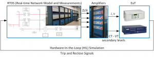
Click here to download Proceedings of the Australian Protection Symposium

The PC operating program DIGSI 4 is the user interface to all SIPROTEC 4, SIPROTEC Compact, SIPROTEC 3 and SIPROTEC 2 devices. It is designed with a modern, intuitive user interface. With DIGSI 4, SIPROTEC devices are configured and evaluated – it is the tailored program for industrial and energy distribution systems. From the numerous protection functions, it is possible to easily select only those which are really required. This increases the clearness of the other menus. The settings can be entered and displayed as primary or secondary values. Switching over between primary and secondary values is done with one mouse click in the toolbar. The DIGSI 4 matrix shows the user the complete configuration of the device at a glance. For example, the assignment of the LEDs, the binary inputs, and the output relays are displayed in one image. With one click, the assignment can be changed. With the CFC (continuous function chart), it is possible to link and derive information without software knowledge by simply drawing technical processes, interlocks, and operating sequences. Logical elements such as AND, OR, timers, etc., as well as limit value requests of measured values, are available. Special attention has been paid to commissioning. All binary inputs and outputs can be set and read out in a targeted way. Thus, a very simple wiring test is possible. Messages can be sent to the serial interface deliberately for test purposes.
Training on DIGSI 4 and DIGSI 5 Training, contact us
DIGSI 5 is the configuration and operation tool for all SIPROTEC 5 devices. With DIGSI 5, you create system topologies, configure hardware and communication networks, set function settings, and perform many further tasks.
You perform all configuration tasks offline from your PC without the need for a SIPROTEC 5 device. You transmit all data online to the SIPROTEC 5 device later on – for example, directly through a communication network. For communication, DIGSI 5 and SIPROTEC 5 are based on current standards such as IEC 61850 and proven technologies such as Ethernet.
There are 3 different variants of DIGSI 5:
For simple applications using individual SIPROTEC 5 devices, select DIGSI 5 Compact. With this variant, you deal with most standard tasks such as setting parameters or reading out process data.
The DIGSI 5 Standard variant has an extended scope of functions. This variant includes, among others, the CFC editor and the Display editor. With these, you can now also create your own symbols. With DIGSI 5 Standard, you simulate the topology of a system as a 1-phase representation and you configure hardware and networks on a graphical basis. DIGSI 5 Standard offers full IEC 61850 support, including system configuration.
DIGSI 5 Premium is the high-end variant of DIGSI 5. This variant contains the DIGSI 5 Test suite for testing SIPROTEC 5 devices and functions. You analyze fault records with SIGRA and you use the advantages of flexible engineering for IEC 61850. CFC debugging is a feature provided in DIGSI to verify the created logic before downloading it to any device. (Elec-Engg provides DIGSI 5 Premium License, more information, Contact Us)
What are the differences between DIGSI 4 and DIGSI 5?
Where Do I Find the DIGSI 4 Manager?
In DIGSI 4, the Manager is the initial platform for editing individual devices, modem connections, and more.
Instead of the DIGSI 4 Manager, DIGSI 5 has a common user interface for all required tools. Working with several overlapping cards is now a thing of the past. The Project Tree is now your control center.
If you prefer a similar representation as in the DIGSI 4 Manager, open the Overview Window. You can view the individual objects with details, as a list or as icons.
What Happened to the MLFB (Order Number)?
Instead of an MLFB (machine-readable product designation), SIPROTEC 5 devices have a product code, in both a long and a short form.
The long product code corresponds to the order number of a SIPROTEC 5 device. You find this number in your order documents. DIGSI 5 can directly interpret this long product code, as every character of the code can be assigned uniquely to a property of the SIPROTEC 5 device.
For easier handling, there is a short product code, which uniquely identifies a long product code. The short product code can be configured directly in DIGSI 5. You can find the short product code on the nameplate of the SIPROTEC 5 device and it is also available during ordering.
How Do I Open a SIPROTEC 5 Device for Editing?
To edit a device in DIGSI 4, you had to open this device with the device editing function. This is no longer necessary in DIGSI 5.
In the Project Tree, you find one entry for each SIPROTEC 5 device offline configuration. This entry summarizes all actions and access points that you need to edit this offline configuration.
Thus, for example, you display the Information Routing matrix by double-clicking to route information in the working area. This also works parallel for several offline configurations.
How Do I Set the Functional Scope of a SIPROTEC 5 Device?
In DIGSI 4, you had to open a device for editing and you had to adapt the scope of functions of the device in the DIGSI 4 device editing function. This is now no longer necessary. In DIGSI 5, you already select a so-called application template when adding a new SIPROTEC 5 device.
Application templates make further project planning simpler for a SIPROTEC 5 device. Each template contains the most important functions that are required for a specific application. Examples of such applications are line protection, motor, and transformer protection.
Selecting a certain application template consequently determines the basic functional scope of a SIPROTEC 5 device. You can change this by adding and removing functions. You can do this with drag and drop in Single-Line Editor, in the Information Routing matrix, or also within the Project Tree.
Why Can I Not Route to CFC and the Display in the Information Routing?
In DIGSI 4, you must route to CFC in the matrix the information that you need for a CFC function, or which is generated as a result of a CFC function. The same applies to the information that you need on the display.
All information that is listed in the information routing is automatically at your disposal in the Function-Chart (CFC) Editor and the Display Editor of DIGSI 5. It is no longer necessary to route to CFC or the display.
The columns for CFC and for the display in the Information Routing matrix serve only to indicate whether an item of information is used within a function chart (CFC) or the display. The display appears automatically as soon as you link an item of information with a function block or an element on a display page
How Do I Edit the Basic Display and the Control Display?
There is no longer any distinction between the main display and the controlled display, and there are now only display pages in SIPROTEC 5 and DIGSI 5.
In DIGSI 5 Standard and DIGSI 5 Premium, for every SIPROTEC 5 device you can generate up to 10 display pages with graphics, text, and measured values and can save them into the SIPROTEC 5 device. You use the Display editor to generate this. You yourself decide on which operating state you use which display page.
Training on DIGSI 4 and DIGSI 5 Training, contact us
Subscribe Elec-Engg on WhatsApp and get the latest update: Save +989129613659 in your contacts and send Subscribe on WhatsApp!

The reverse busbar protection is a cost-effective solution for the accelerated clearance of busbar faults in distribution systems. It can only be applied on single busbars with a fixed direction of power flow and fault current flow. In picture 3, a typical application is shown.
Overview:
For this application, the protection device on the incoming bay (usually the transformer bay) will be provided with blocking signals from the outgoing bays (the feeder bays). If one of the outgoing bays (feeder bays) detects a fault, (pick-up signal), this bay must route a blocking signal to protect the incoming bay. This blocking signal prevents the fast tripping of the incoming bay (I>> stage). The block signal may only be present for one second.
For this application, a CFC chart in the incoming bay is required. Although it is possible to allocate a signal from a binary input so that it provides the blocking of a protection stage it is not possible to give more than one binary input to directly block one protection stage (the reason being that if two binary inputs that provide the same blocking signal have a different state, the device logic would not know which of the two binary inputs should be used).
Example application with 7SJ6 relays:
The I>> stage in the in-comer will be blocked with the signal 1721 >Block 50-2., and the signal 1724 >Block 50N-2. These signals must be allocated with source CFC. (see picture 1)

For example, a feeder relay (or many feeder relays with a blocking signal connected in parallel) designated as LHBB-block provides a blocking input signal via binary input to the incoming bay relay. This signal is routed to the user-defined single-point annunciation in the matrix (picture 1), binary input 20. Similarly, the second feeder relay (or second group of relays) designated as RHBB-block is/are allocated to binary input 21. Two new user-defined single-point annunciations, which have to be connected to the binary inputs must be generated. These signals (in picture 1) are called LHBB-Block and RHBBBlock. These signals must be routed with the destination CFC so that they will be available inside the CFC charts. In the CFC chart, the LHBB-Block and RHBB-Block signals are connected via OR-gate. The output of the OR gate triggers a timer that restricts the blocking signal to one second. This is achieved by applying the timer output via a negator to an AND gate (AND gate 4 in picture 2). The timer output will change from 0 to 1 one second after the OR gate output changes to 1. At this point, the second input of AND gate 4 will change to 0, thereby removing the blocking signal which is routed from OR gate one via the AND gate to the right-hand margin. As shown in picture 2, the blocking signal from the CFC chart is derived from the output of the AND gate and is routed to the signals 1721 >Block 50-2. and 1724 >Block 50N-2. Please note that the gates must be executed in the correct sequence, i.e. sequences 10 to 13 as shown in picture 2. The sequence of execution may commence with a different
number, depending on other logic located in the same execution layer, PLC_BEARB). The OR gates must be first in the sequence, followed by the timer, negator, and AND gate in turn.
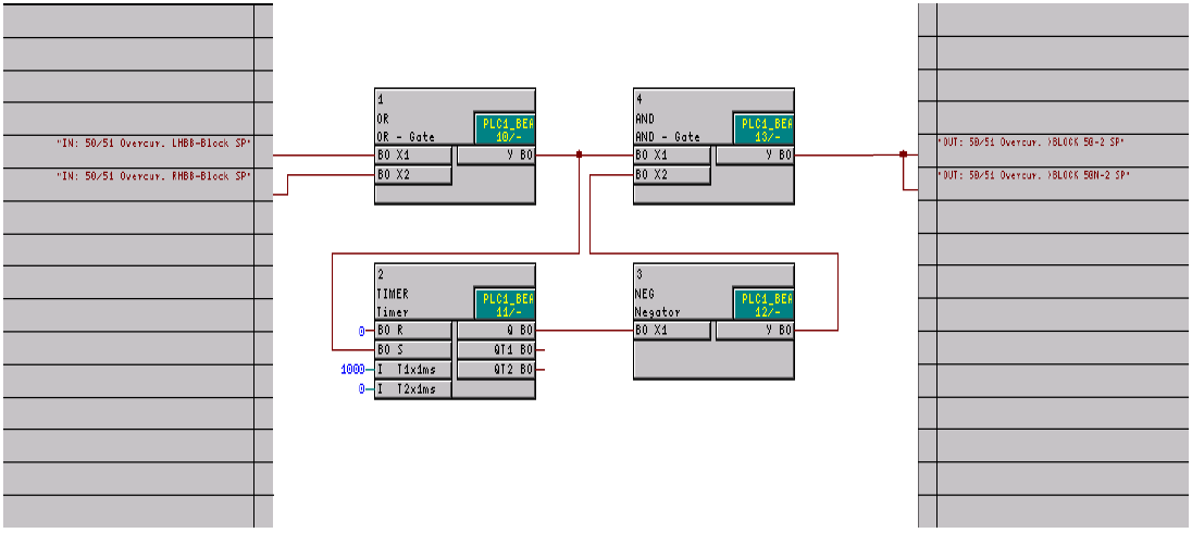
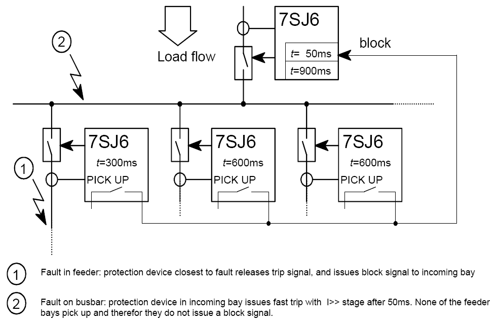

DIGSI 4 is for the configuration of all SIPROTEC 4, SIPROTEC Compact, SIPROTEC 3, and SIPROTEC 2 devices which are designed with a modern, intuitive user interface. With DIGSI 4, SIPROTEC devices are configured and evaluated.
This package contains DIGSI Video Tutorials
More about DIGSI 4:
From the numerous protection functions in SIPROTEC devices, it is possible to easily select only those which are really required. The settings can be entered and displayed as primary or secondary values. Switching over between primary and secondary values is done with one mouse click in the toolbar.
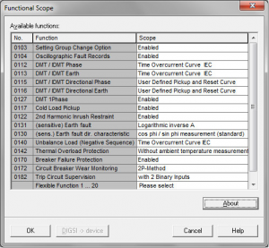
The DIGSI 4 matrix shows the user the complete configuration of the device at a glance. For example, the assignment of the LEDs, the binary inputs, and the output relays are displayed in one image. With one click, the assignment can be changed.
With the CFC (continuous function chart), it is possible to link and derive information without software knowledge by simply drawing technical processes, interlocks, and operating sequences. Logical elements such as AND, OR, timers, etc., as well as limit value requests of measured values, are available. Special attention has been paid to commissioning. All binary inputs and outputs can be set and read out in a targeted way. Thus, a very simple wiring test is possible. Messages can be sent to the serial interface deliberately for test purposes.


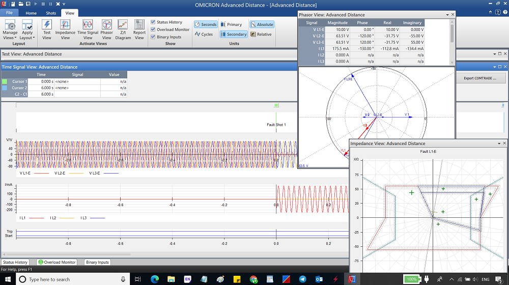
OMICRON Test Universe 4.00 trainig package
Please contact us for this training package
Advanced Power in OMICRON Test Universe V4.00
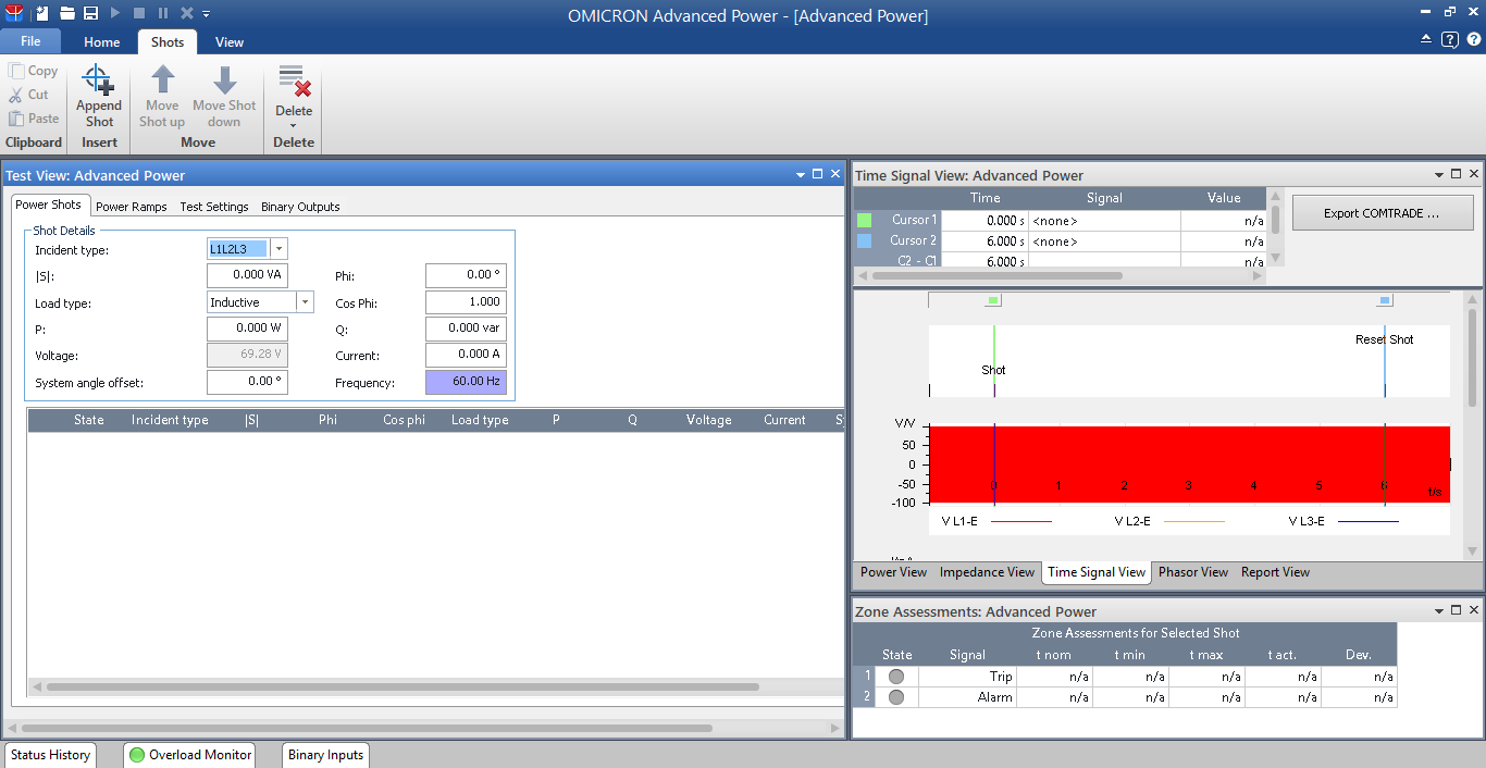
Advanced Power Module in Test Universe V4

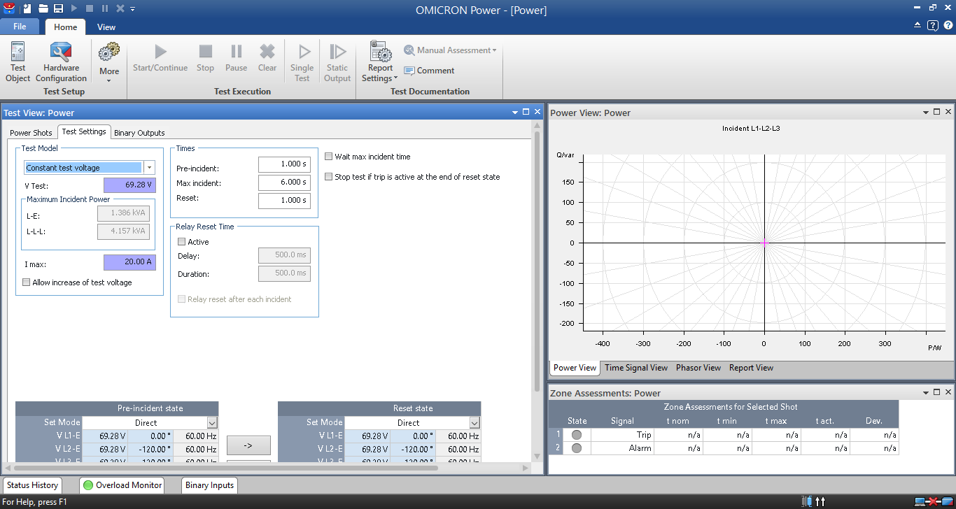
Power Module in Test Universe V4

DIGSI 5 is for configuring, parameterizing, and operating SIPROTEC 5 protection, combination, and bay devices. With a PC or a notebook, you can parameterize the devices via the interfaces and export and visualize the fault data. DIGSI 5 comes in different variants (Compact, Standard, and Premium) that provide different functionalities. To use DIGSI 5 Standard and Premium, you need a license key for each computer you are running DIGSI 5 on. If you execute the software without a license key, it will be always available as DIGSI 5 Compact edition or as a Trial version for 30 days. The licenses are provided on USB sticks.
DIGSI 5 V7.80 needs high performance specifications of the used operating system version. Therefore, it is recommended to install DIGSI 5 V7.80 on Intel® Core™ i5 with 16 GB of RAM,
With DIGSI 5 V7.80, you cannot upgrade projects created with DIGSI 5 V6.20 and below directly to DIGSI 5 V7.80 due to the technical limitations. During the installation of DIGSI 5 V7.80, you will be prompted depending on the current DIGSI 5 installation on your PC. The following possibilities exist:
DIGSI 5 V7.80 can be used along with any available DIGSI 4 version on the same system. If you install DIGSI 4.82 or earlier after DIGSI 5, you need to reinstall the latest Automation License Manager (ALM) after installation of DIGSI 4. ALM setup is provided on the DIGSI 5 DVD in the folder \Automation License Manager.


DIGSI 4.93 is the user interface to configure SIPROTEC 4, SIPROTEC Compact, and SIPROTEC 3 devices. It is designed with a modern, intuitive user interface. With DIGSI 4.93, from the numerous protection functions, it is possible to easily select only those which are really required. The settings can be entered and displayed as primary or secondary values.
The DIGSI 4 matrix shows the user the complete configuration of the device at a glance. For example, the assignment of the LEDs, the binary inputs, and the binary output relays are displayed in one image. With one click, the assignment can be changed.
DIGSI 4 and DIGSI 5 online Training course, contact us
With the CFC (continuous function chart), it is possible to link and derive information without software knowledge by simply drawing technical processes, interlocks and operating sequences.


Relay protection against the high current was the earliest relay protection mechanism to develop. From this basic method, the graded overcurrent relay protection system, discriminative short circuit protection, has been formulated. This should not be mixed with ‘overload’ relay protection, which typically utilizes relays that function in a time-related to some degree to the thermal capacity of the equipment to be protected. On the contrary, overcurrent relay protection is completely directed to the clearance of short circuits, even though with the settings typically assumed some measure of overload relay protection may be obtained.
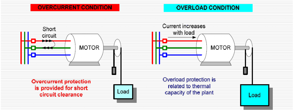
Instantaneously overcurrent relay operates when the current exceeds its Pickup value. The operation of this relay is based on the current magnitude and it is without any time delay.
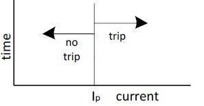
The current/time-tripping characteristics of IDMT protection relays may need to be changed according to the functioning time needed and the characteristics of other relay protection elements used in the electrical network0.10 For these needs, IEC 60255 determined the number of standard characteristics. These are:
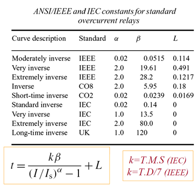
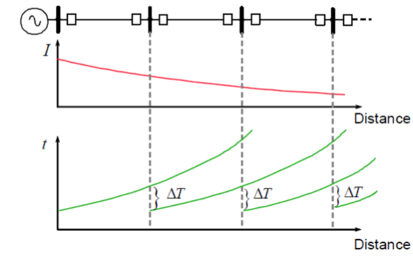
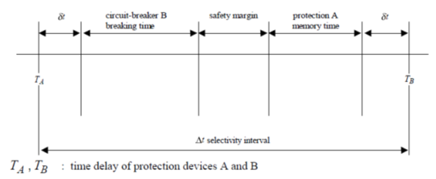
A high-set instantaneous device can be utilized where the source impedance is small in comparison with the protected circuit impedance. This allows a decrease in the operating time at high short circuit levels possible. It also enhances the overall electrical system grading by allowing the ‘discriminating protection curves’ behind the high set instantaneous device to be reduced. One of the benefits of high-set instantaneous devices is to decrease the tripping time of the circuit protection. If the source impedance stays constant, it is then feasible to accomplish high-speed relay protection over a large part of the protected circuit. The quick short circuit clearance time helps to decrease damage at the short circuit location. Grading with the protection relay directly behind the protection relay, which has the instantaneous devices enabled, is accomplished at the current setting of the instantaneous devices and not at the maximum short circuit level.
Leave a comment on this post, we will send you the “Overcurrent Protection Fundamentals. pdf ” for FREE
When a short circuit current can go in both directions through the protection relay location, it may be required to make the response of the protection relay directional by the initiation of a directional control device. The device is provided by the use of extra voltage inputs to the protection relay. There are many ways for an appropriate connection of voltage and current signals. The different connections depend on the phase angle, at a unity system power factor, by which the current and voltage used in the protection relay are displaced

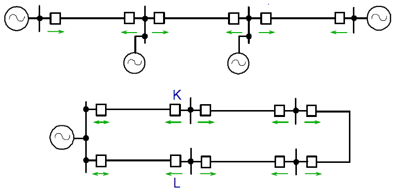
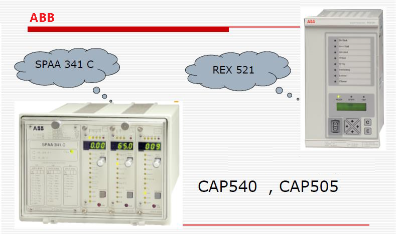
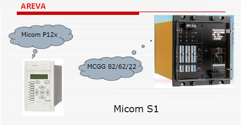
Leave a comment on this post, we will send you the “Overcurrent Protection Fundamentals. pdf ” for FREE
تأريض غلاف الكابل Cable Sheath Earthing
Stub Protection
Tee Protection
Anti-Pumping circuit
Power Line Carrier (PLC) Line Trap
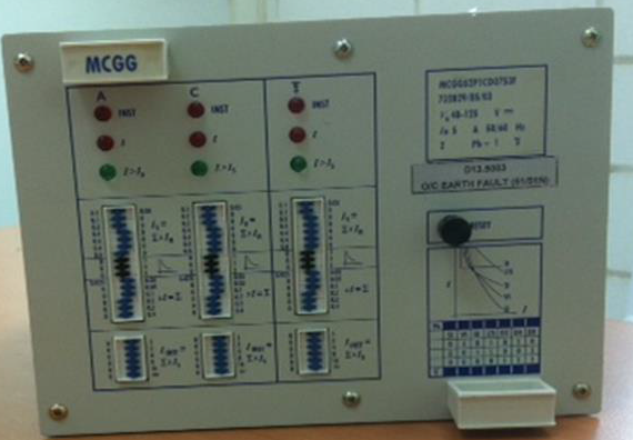
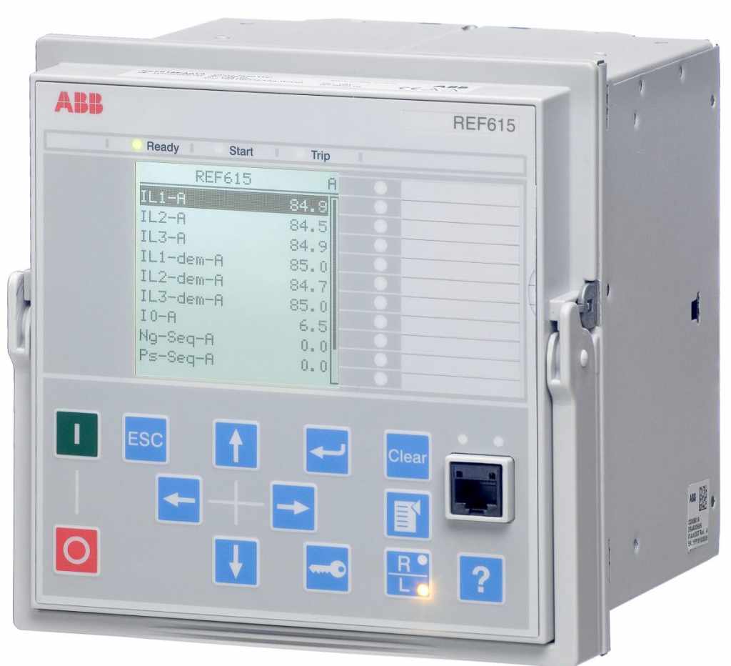
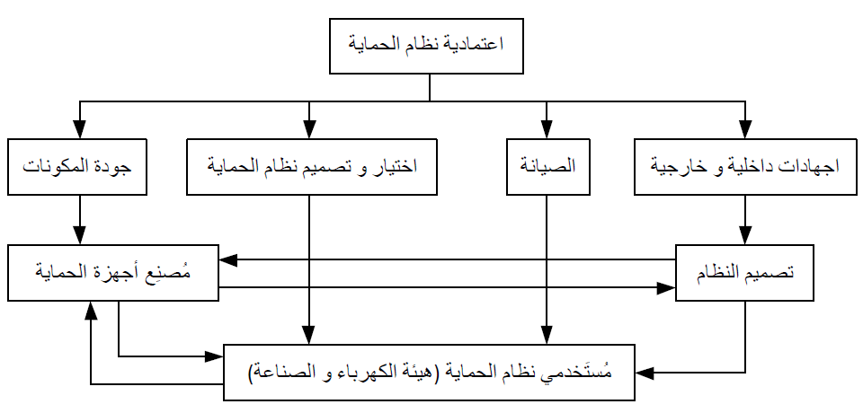
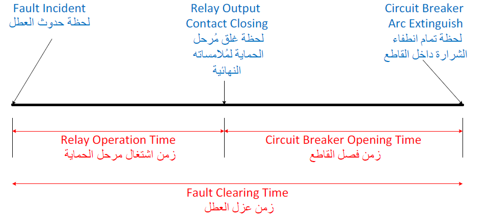
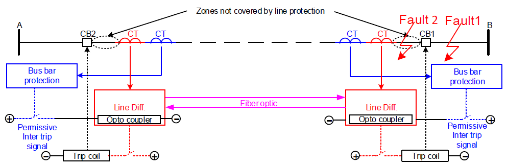
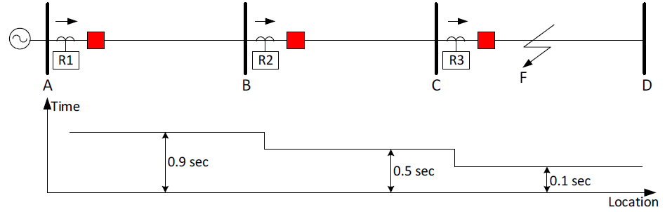
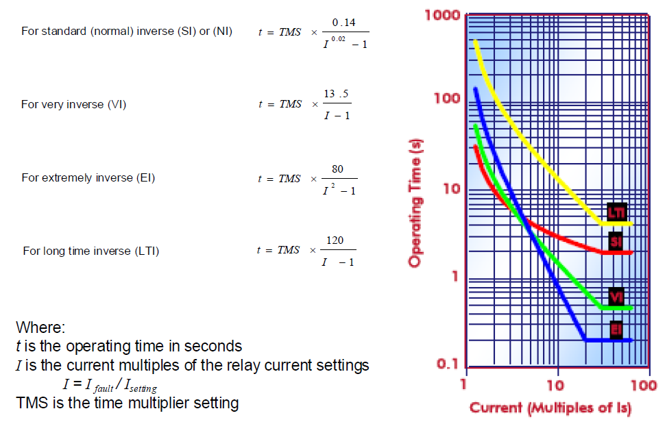
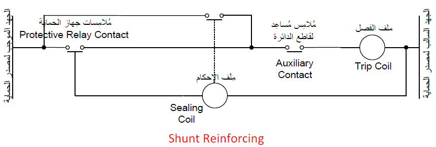
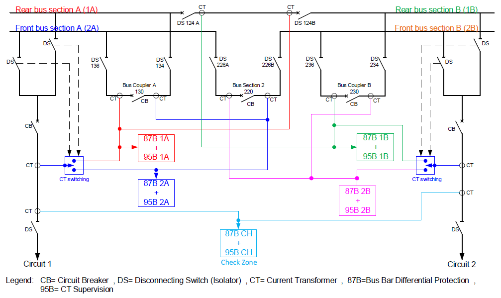
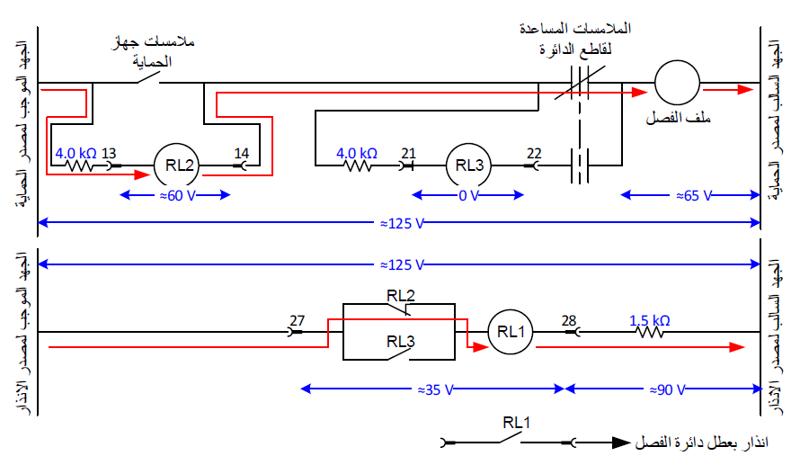
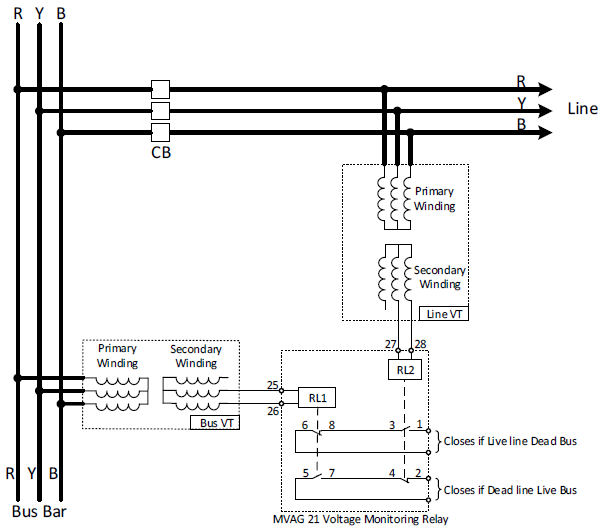

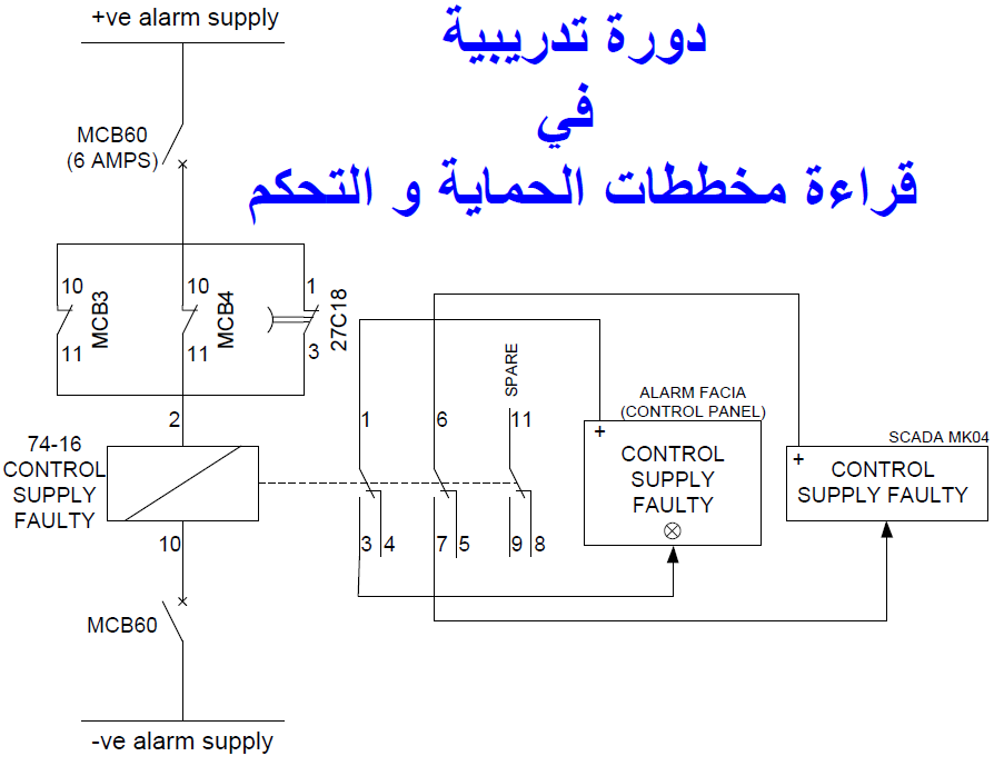


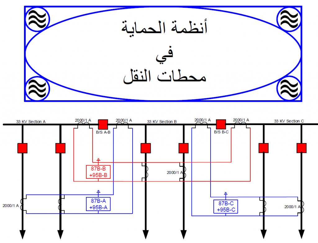

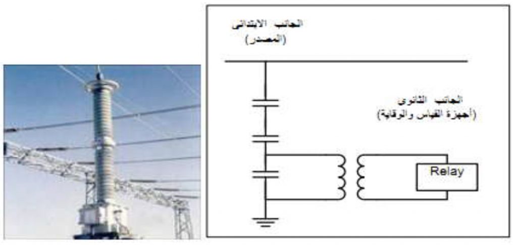


Devices and description of this sample SLD
Following shows the ANSI code and functional


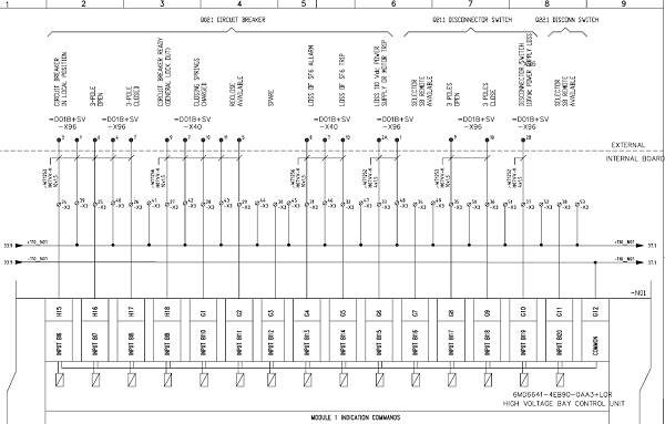
for Full Project: Contact US
In today’s competitive market scenarios, power utilities are under tremendous pressure to cut down their maintenance costs as they form a significant portion of the operation costs. This has led the utilities to adopt condition-based maintenance of the equipment rather than the usual preventive maintenance being carried out at a fixed interval of time. Maintenance intervals are normally fixed based on the type of equipment and sometimes on the equipment history. However, tests or measurements are also carried out to assess the condition of the equipment.
File Type: PDF
Number of Pages: 129
contact us or write a comment on this post
This section briefly describes the probable causes of failure of significant substation equipment viz. Power Transformers, Reactors, Circuit Breakers, Instrument Transformers, Surge Arrestors, etc., and remedial measures taken to prevent such failures.
This section briefly covers the maintenance practices/techniques being adopted by the power utilities for switchgear pieces of equipment installed in EHV/HV stations. However, competitive market utilities are under tremendous pressure to bring down maintenance costs in the present scenario. This has led to the adoption of condition-based monitoring rather than conventional scheduled maintenance. The frequency of the condition-based maintenance is fixed based on the type of equipment and its previous history. Tests or measurements are carried out to determine the condition of the equipment. It is the general experience of practically all the utilities that most of the equipment doesn’t show any abnormality during scheduled maintenance and there is no guarantee that the equipment shall not fail before the next scheduled maintenance. Thus, the scheduled maintenance efforts are in vain as well as costly because of shut-down time and manpower costs. Hence modern condition-based techniques are being adopted which are designed to continuously monitor the function parameters and also assess the deterioration of the components before a mal-operation occurs.
The techniques/procedures being adopted for both preventive maintenance and condition-based monitoring in respect of EHV transformers and reactors are briefly discussed in this section.
Over a hundred years ago, Gautapercha was used as an insulating material for cables, which worked satisfactorily for telegraphic lines. However, with the development of the power current, changes in cable insulation became essential. While carrying power currents, cables became hot and heat sensitive. Gutta-percha was, therefore, found unsuitable for insulated power conductors. To suit the new requirements, a superior insulation system using a fibrous material was dried, impregnated under vacuum, and enclosed in a seamless lead sheath. They were the forerunners of paper-insulated lead sheathed cables that came into existence around 1890 and have been used since then.
Most of the equipment in a substation is provided with sufficient insulation from breaking down, yet others like bus bars, terminations of high voltage equipment, the equipment connected to take-off structures, etc; are bare unlike in gas-insulated substations. There is a need for assurance that the breakdown or flashover will not occur to the operating personnel and that some safe distance is to be maintained. As per the studies and experience gained over a period, various bodies like CEA in India and elsewhere are issuing guidelines from time to time to maintain certain minimum safety clearances depending upon the voltage class from bare conductors and parts of various types of equipment exposed to the atmosphere. The provisions are mandatory and all the concerned like utilities and consumers have to maintain these minimum safety clearances. They are necessary for the safety of the operating personnel and the safety of the equipment.
One of the important aspects of the operation of protective equipment is proper earthing. By earthing, it means making a connection to the general mass of the earth. Earthing also increases the reliability of the supply service as it helps to provide stability of voltage conditions, prevent excessive voltage peaks during disturbances, and also as a means of providing a measure of protection against lightning. Its use is widespread in the supply network right from the generation to the apparatus on the consumer premises. The requirements of earthing vary at different points based on the fault level, soil resistivity, and the safety considerations
Instantaneously One of the important aspects of the operation of the protective equipment is proper earthing. By earthing, it means making a connection to the general mass of the earth. Earthing also increases the reliability of the supply service as it helps to provide stability of voltage conditions, prevent excessive voltage peaks during disturbances, and also as a means of providing a measure of protection against lightning. Its use is widespread in the supply network right from the generation to the apparatus on the consumer premises. The requirements of earthing vary at different points based on fault level, soil resistivity, and safety considerations.
Instantaneously overcurrent relay operates when the current exceeds its Pickup value. The operation of this relay is based on the current magnitude and it is without any time delay.
File Type: PDFNumber of Pages: 129
Download: contact us

General:
Three Phase:

Single Phase
Check the motor winding ohms reading using a multimeter or ohmmeter. (C to S, C to R, S to R). The reading for starting to run should be equal to C to S + C to R.
Correct electrical terminal identification
There are three-terminal connections on a hermetically sealed motor compressor and are as follows: Common (C), Start (S), and Run (R). To identify the correct terminal connection the following procedure applies:
Transformers and Generators are voltage sources. They are traditionally protected by an Overcurrent + Earth fault relay, normally mounted in the breaker panel. It should be noted that this protection alone is not adequate.
When an earth fault occurs within the zone defined as A in the following figure (Internal fault), or within the machine, the fault current will circulate within the zone or the machine. The fault current will not flow through the CTs connected to the O/C +E/F relays near the breaker. This will cause a no-trip situation when there is a fault in zone A.
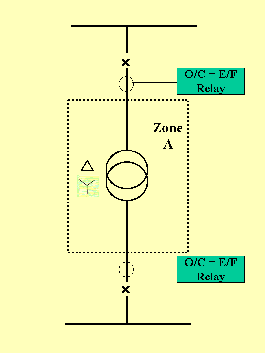
Consequently, a separate scheme is required to detect internal earth faults. This scheme is called Restricted Earth Fault (REF) scheme. It should be noted that the fault currents in Zone A are limited by the impedance of the equipment in the zone – for transformers and generators it is very low – the fault currents can rise very fast and damage the equipment. Consequently, REF protection is of utmost importance for generators and transformers.
The name Restricted is derived since the objective of the protection is to detect the earth fault is restricted to the specific zone, starting from the breaker to the machine terminals. In the case of a generator, the machine terminal is the neutral point. In the case of a transformer, the machine terminal becomes the star point of either the primary or secondary winding or both. In the case of delta winding, it is the winding itself.
It is well established that the sum of currents at the beginning of zone A should be equal to the sum of currents exiting the zone. Two sets of CTs are used to derive the sum of currents at the inlet and exit. A fault in the zone will result in a difference in current.
An overcurrent relay is used to measure the difference in the sum of these currents. Please refer to fig.2 where a typical REF scheme is shown. The REF relay is connected between P & S. It will pick up if there is enough voltage across P-S to drive the pickup current through the relay.
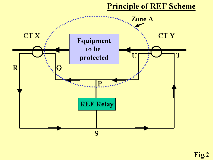
There are two current sources in the CT secondary circuit PQRSTU:
Under normal conditions, a vectorial sum of the currents of these two CTs will be equal and opposite in the branch P-S (ie) the resultant current in the branch PS will be zero. In this situation, the currents of CT X and CT Y will circulate in the loop PQRSTU. The voltage across P-S will be zero.
When there is an earth fault within zone A, the currents of X & Y CTs will not be equal – a small difference in current will flow in the branch P-S. This current will result in a voltage across P-S – since the current flows through the relay impedance. If this voltage is adequate to operate the relay, the relay will pick up – thus detecting a fault within the zone.
For a fault outside the zone, the currents through CTs X & Y will be the same the resultant current through P-S will still be zero and the relay will not pick up. In this case, the fault has to be cleared by another O/C + E/F relay connected near the breaker.
We have said in sections 3 & 4 that the REF relay will detect a fault within a zone restricted between two CTs and it will not detect a fault outside the zone defined by the CTs. This is true, only for ideal conditions- where the two CTs are perfectly matched. Following mismatches will occur under practical situations in the field:
The cumulative effect of all the above can make the relay trip even when there is a full load current flowing in the primaries – through the primary side currents are the same, the secondary side currents need not be the same – a voltage sufficient to trip the REF relay may develop across P-S and hence the relay will trip.
To make the relay insensitive to this voltage produced by CT mismatch, a resistor is added in series with the relay. Once this resistor is added, the relay will need a voltage that is higher than the voltage produced by the CT mismatch. This resistor is called a stabilizing resistor – this is an important component in the REF scheme –since this ensures stability in the scheme by avoiding spurious tripping.
It should be noted that the actual input circuit to trip mechanism (consisting of the relay + stabilizing resistor) has become a high impedance circuit. If the relay has to trip, the CT secondaries should produce sufficiently high enough voltage to activate the relay, after allowing for the drop across the stabilizing resistor.
To ensure the CTs produce enough voltage, an additional specification the Knee point voltage – is included for the CTs used for REF protection.
Knee point voltage (KPV)is defined as the point on the magnetizing curve (of the material used for the CT core) where the core will need a 50% increase in the magnetizing force (ampere-turns) to cause a 10% increase in the flux density. (voltage build-up across secondary). In effect, KPV defines the end of the linear portion of the BH curve. The higher the KPV, the larger the linear zone, and the better will be secondary output for higher fault currents. The higher the KPV, the better the chances of a high impedance relay trip.
The value of the stabilizing resistor and KPV will depend on the following parameters which are unique to a given feeder:
L&T manufactures a high impedance Overcurrent relay which is ideally suited for the REF protection of generators and transformers. Typical schemes are shown in figure 3 and figure 4.
L&T offers a unique feature in the REF relay SC14S – in addition to the instantaneous trip, the user can select a definite time delay of either 100 milliseconds or 200 milliseconds. In the case of small transformers & generators ( up to 5 MVA), the feeder trips during breaker closing. This mainly is due to the large inrush current causing a momentary difference in CT secondary currents due to a mismatch in saturation characteristics. A 100-millisecond time delay will help in this case.
Figure 3 shows a typical scheme for REF protection for generators. The scheme envisages the following;
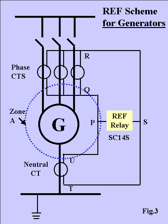
The following figure shows a typical scheme for REF protection for transformers. It should be noted that transformers will need two REF schemes – one on the primary side and the other on the secondary side.
For the transformer’s primary side, which is usually delta connected, the following are envisaged in the REF scheme :
For the transformer’s secondary side, which is usually star connected, the following are envisaged in the REF scheme :
All you need to do is to download these excel files and you can work with them straight away. These test sheets can be filled on your PC or can be printed and filled in by hand. These test sheets are not copyrighted so you can edit them, change them as you wish.
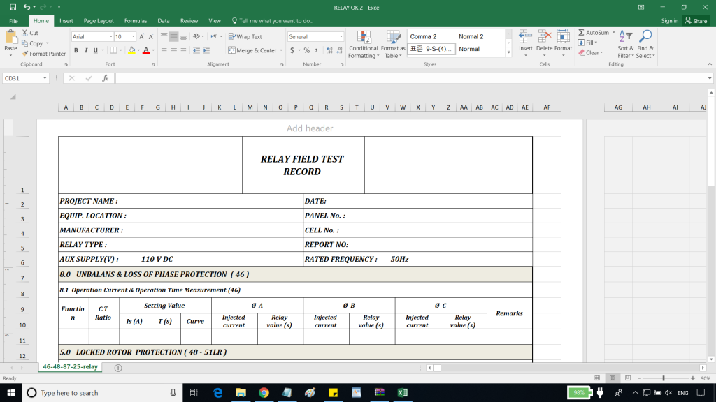

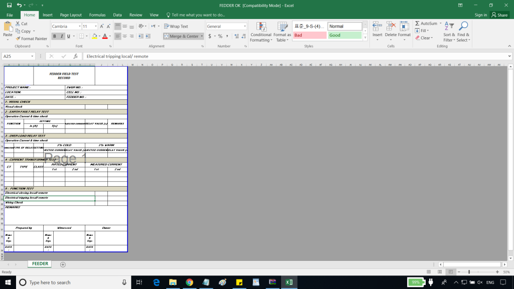
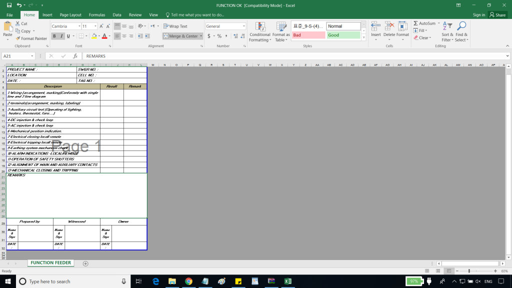
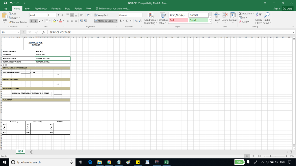
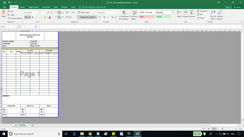

Elec-Engg, provides design and engineering services on power projects, ranging in complexity from simple low voltage industrial designs to 500 KV substation design engineering. Elec-Engg can prepare all plans and schematic drawings in AutoCAD to enable customers to examine system design concepts and conformity with total design criteria before the manufacturing, construction, and permit process.
Protection and relaying design
Substation automation design
Device and equipment specification


Thanks for your sweet trust. After successful Payment,
Please leave a comment on this post, or contact Us. We will send you the file or your download link
Thank you for your interest in our products. Please feel free to contact us if you have any questions or need more details.


Pre-order
Suggested Combined packages


Learning is a continuous process and enables us to be competitive in our field. Consistent with this belief and built on a strong experience in this field, we offer video training courses for practicing professionals in the area of Substation Automation and Protection Relays. The material of each course is designed to help you to be a professional in the field.
we provide training courses at your site or online, contact us for reservations.

ETAP has been designed and developed for engineers to study different aspects of power systems in one integrated package.
This course is structured into 4 chapters, with theory and practical examples. It is designed for protection engineers to understand the power system, short circuit concept, protection, and coordination.
Chapter 1, part 01: overviews different tools in ETAP with an example. ETAP offers a suite of fully integrated electrical engineering software solutions including load flow, short circuit, protection and coordination, harmonic analysis, transient stability, cable ampacity, arc flash, optimal power flow, and more. Some of these tools may not be required in our study. So we should know which part is the most important tool for us. This part overviews different parts of ETAP before starting the course. In this way, we can find the main tools and parts on which we should focus on.
Chapter 1, part 02: An introduction to ETAP software. We start with creating a new project and explaining different toolbars and menus in ETAP.
Chapter 1, part 03: This part overviews the main parameters of a busbar, 2 winding transformers, and 3 winding transformers.
Chapter 1, part 04: Overview of the main parameters of a transmission line and cable.
Chapter 1, part 05: overviews the main parameters of a static load, lumped load, and power grind.
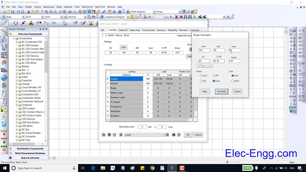
Chapter 2, Part 01: shows how to study parameters with load flow analysis. To do so, we run a load flow analysis on a simple one-line diagram and study the effect of different parameters.
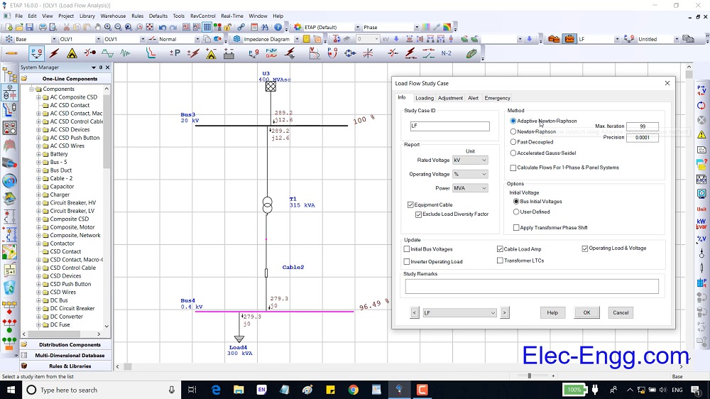
Chapter 2, Part 02: overviews the load flow study case and plot option settings.

Chapter 2, Part 03: presents a practice to understand the parameters of load, equipment cable, busbar, cable, and transformer deeply. Then it presents load flow and load analyzer tools.
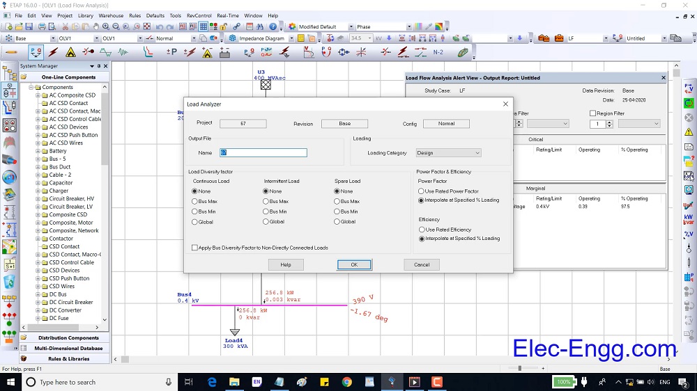
Chapter 2, part 04: overviews the main parameters of low voltage circuit breaker and high voltage circuit breaker.

Chapter 2, part 05: overviews the main parameters of an induction machine and how to model an induction machine in three different methods.
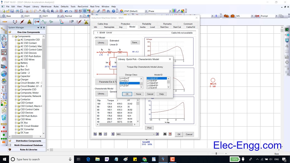
Chapter 2, part 06: overviews the main parameters of a synchronous generator.
Chapter 2, Part 07: presents a practice to understand the parameters of an induction machine and a synchronous generator deeply.
Chapter 2, Part 08: presents how to remove the critical alarm. To do so CB overload, cable overload, and transformer overload alerts have been removed. To remove these alerts, we should know how to do cable sizing and transformer sizing in ETAP.
Chapter 3, Part 01: shows the effect of different parameters in the short circuit current. An induction motor can inject current to a grid even more than an equivalent generator, this part show this concept in ETAP.
Chapter 3, Part 02: explains the settings in the short circuit analysis. To explain the parameters of short circuit analysis and understand the short circuit modeling in ETAP, we have simulated an AG fault in PSCAD.
Chapter 3, Part 03: presents several duties and tools in short circuit analysis mode.
Chapter 4, Part 01: overviews the elements which are related to relay protection and coordination.
Chapter 4, Part 02: shows overcurrent parameters in ETAP and relay configurations software. The setting of overcurrent relays (P121 and distance relay SEL 421) are shown in the configuration software (Esergy studio and AcSELerator quick set software).

Chapter 4, Part 03: In this part, three-phase voltage and currents are injected into the SEL 421 with a secondary test kit (Omicron CMC 256) to explain the values in a relay and test the intravenous overcurrent function.
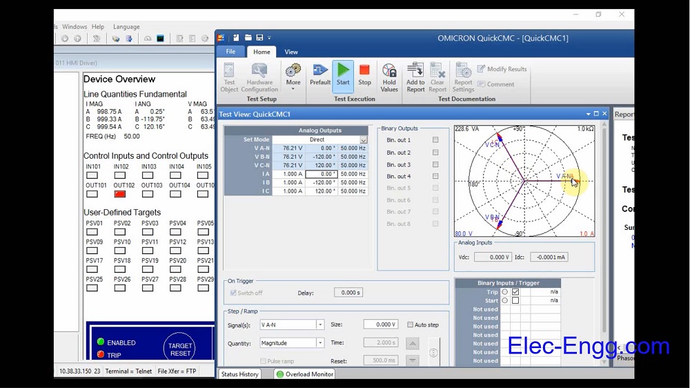
Chapter 4, Part 04: presents how to calculate the CT ratio and time delay overcurrent elements (Ansi 51). Then the coordination between two relays is explained with the help of start view tools.
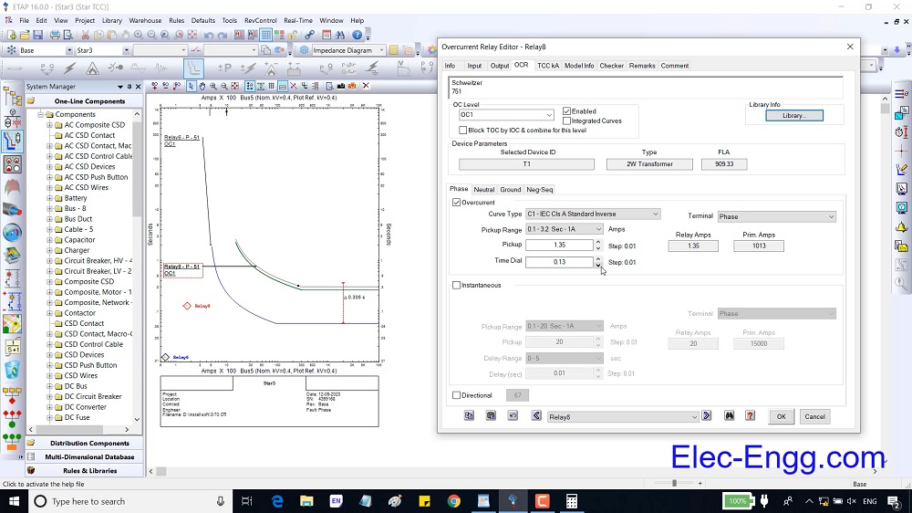
Chapter 4, Part 05: the coordination between three relays and how to test the coordination with the help of the sequence viewer tool are presented.
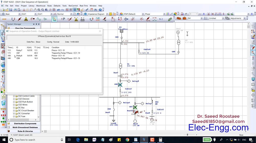
Chapter 4, Part 06: This part explains the plot option parameters in the Star View.
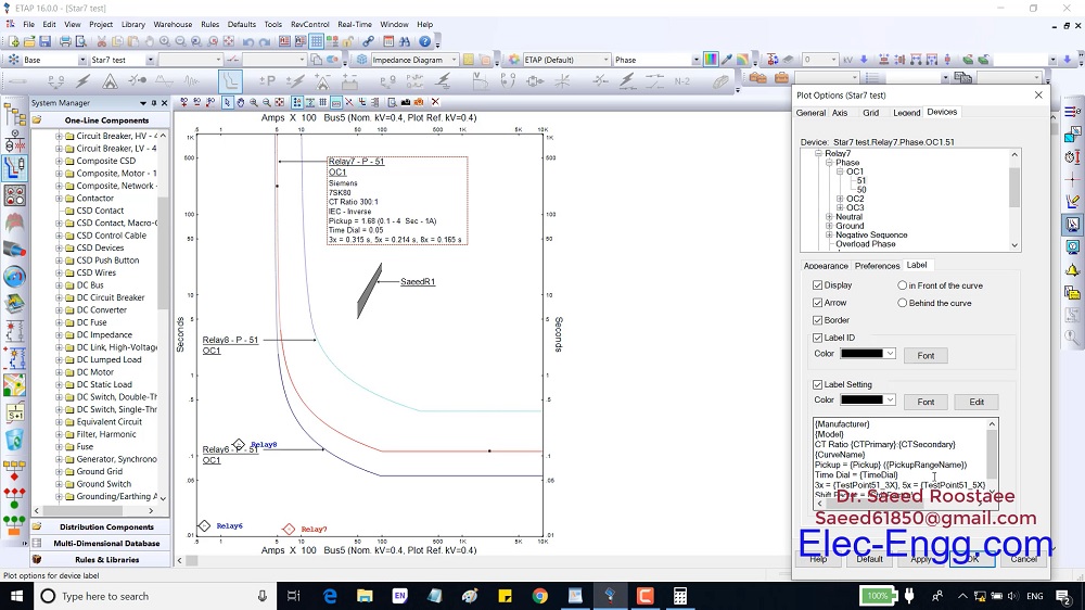
Chapter 4, Part 07: This part explains how to set instantaneous overcurrent parameters (ANSI 50).

Chapter 4, Part 08: presents how to calculate overture ground elements in ETAP and how to set these parameters in the relay.
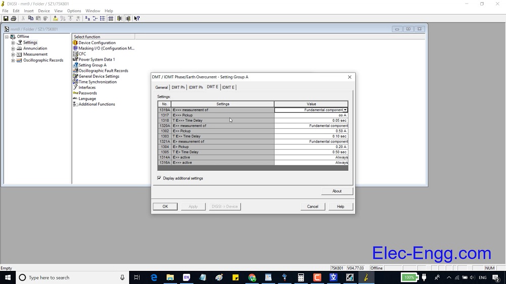
Chapter 4, Part 09: This part presents how to add a proper fuse to a feeder and coordinate the relays with the fuse.
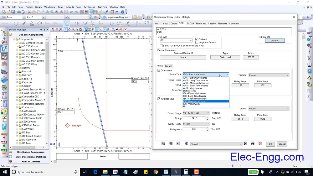
Chapter 4, Part 10: This part explains the protection page of the main elements and how to protect an element with an overcurrent element.
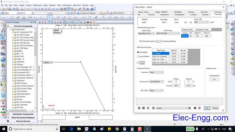
Chapter 4, Part 11: This part presents helpful tools in the protection and coordination study room.
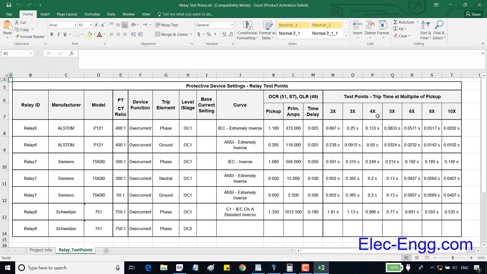
WhatsApp: +989129613659
Email: info@elec-engg.com
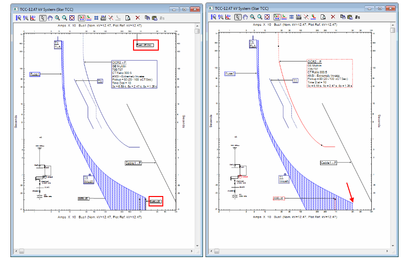
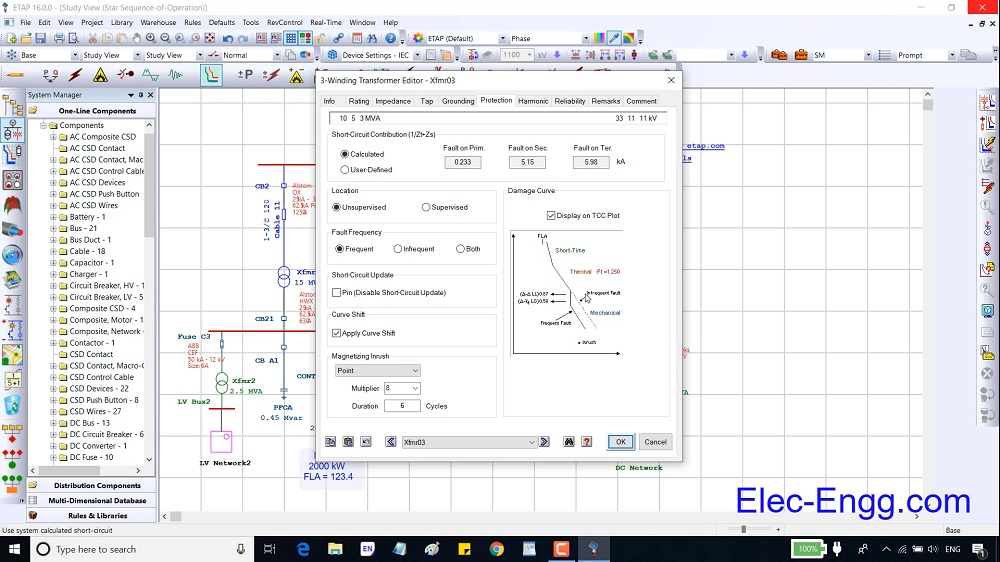
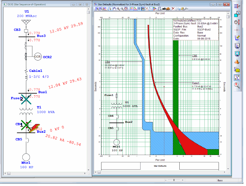


These days can’t perform many of the required analyzes in electrical networks without using the relevant engineering software. Therefore, engineering software has been very effective in industrial environments. One of the most famous software is ETAP which is used in the analysis of distribution networks in industrial Plants and is made by the Operational Technology company. In this training package, in addition to collecting the required technical information in an attractive multimedia environment, various analyzes, and how to do them using ETAP software are presented practically.

Learning is a continuous process and enables us to be competitive in our field.
In this package, you get Trained DIGSI 4 and DIGSI 5 to work with SIPROTEC 4 & 5, how to work with Etap software, and how to use IEC 61850 for integration and communication between different equipment brands.
Product detail:
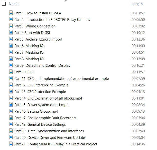
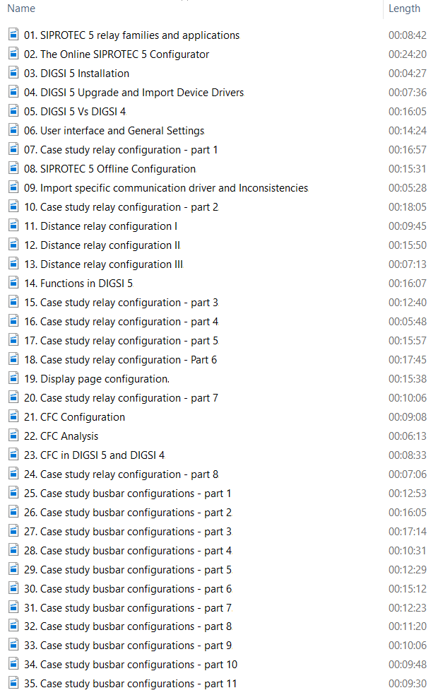

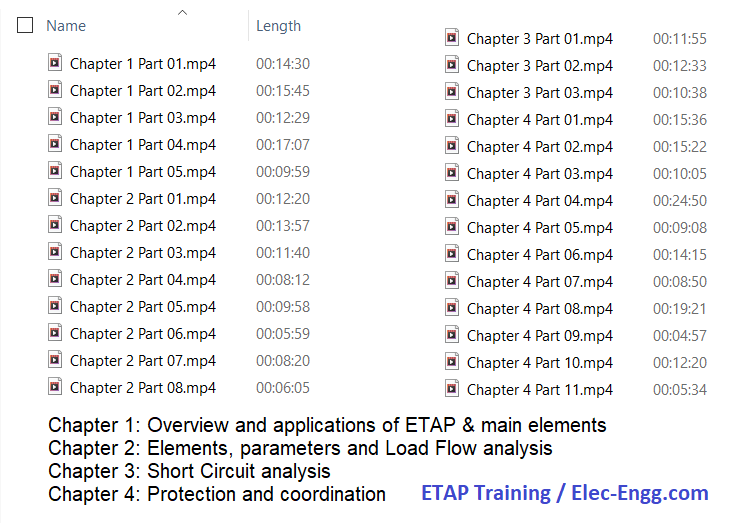

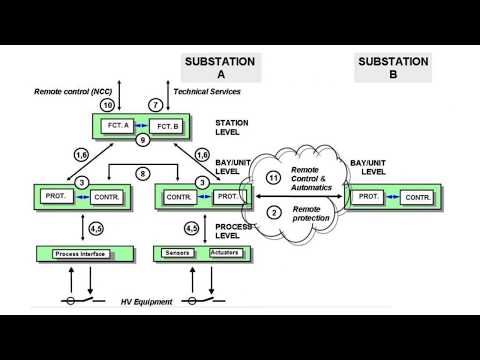


contact us to get this impressive IEC61850 collection

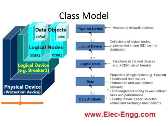


ABB CAP 505 (Computer Aided Programming system) can be used to config the ABB RED 500 and SPACOM series. This training course introduces the hardware structure of the RE 500 series and then the configuration procedure of these relays in CAP 505.
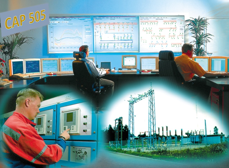
Pre-recorded Videos
Course Contents:
How to access the training course
Buy now and start learning:

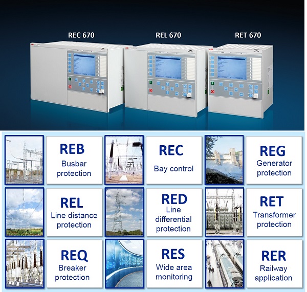
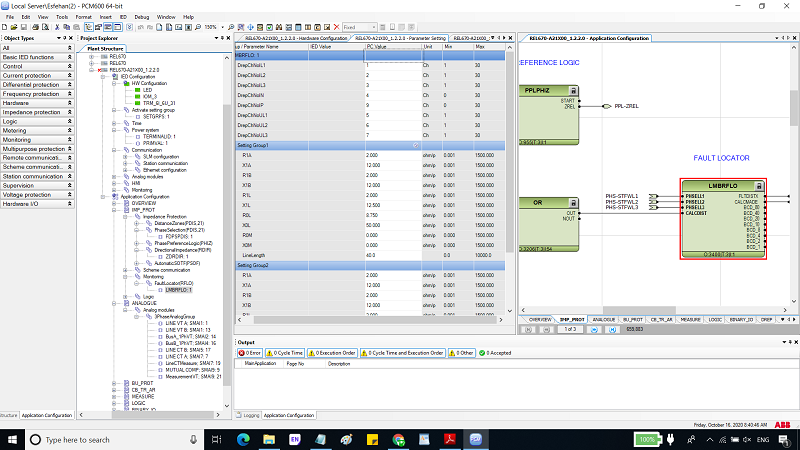
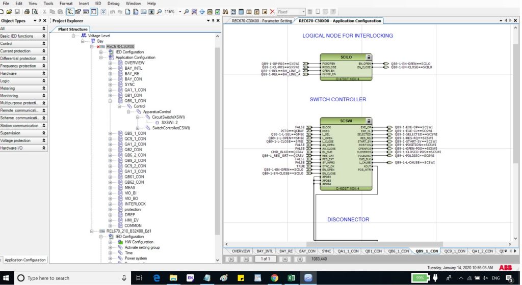


Click here to enroll in the course and get the certificate of the IEC 61850 compilation course
https://elec-engg.com/iec-61850-training-course/

Training delivery: Face-to-face / Online sections on Google Meet + pre-recorded videos
Trainer: Dr. Saeed Roostaee
Using Wireshark for traffic analysis in digital substations

Content:
Supplementary Files: The important related files/ videos /software and attached to the course as extra files.
Any queries, please feel free to contact me at: saeed61850@gmail.com
Part A: Introduction, general settings, Hardware & connection, Impedance/Vector/report View, the test object, …
Part B: Overcurrent and Directional Overcurrent Functions (67, 67N, 50, 51, 50N, 51N)
Part C: Differential Protection Functions (87G, 87T, 87L)
Part D: XRIO and PTL
Part E: Impedance Protection Functions
Part F: Autoreclosure Function (ANSI 79)
Part G: Voltage and Frequency Protection Functions (ANSI 27, ANS59, ANSI81O, 81U)
Part H: Study functions, testing, and commission of SIPROTEC 7UT6
Part K: Study functions, testing, and commission of MiCOM P44x

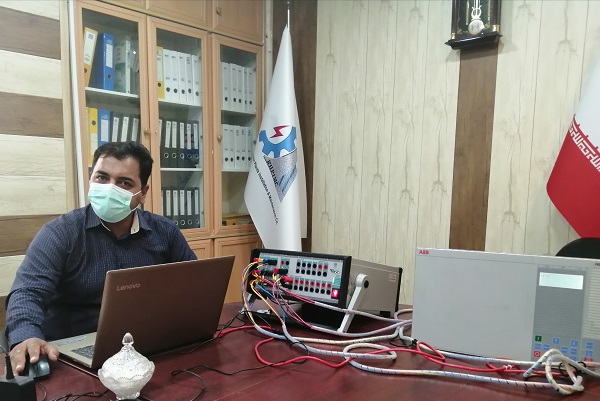

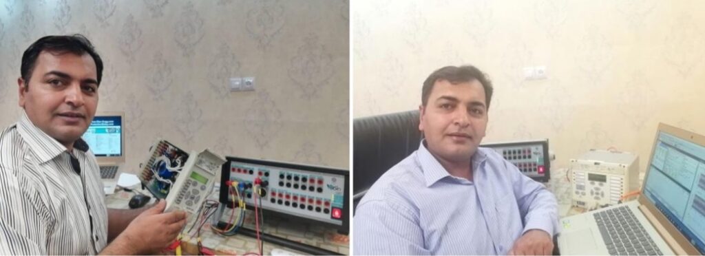
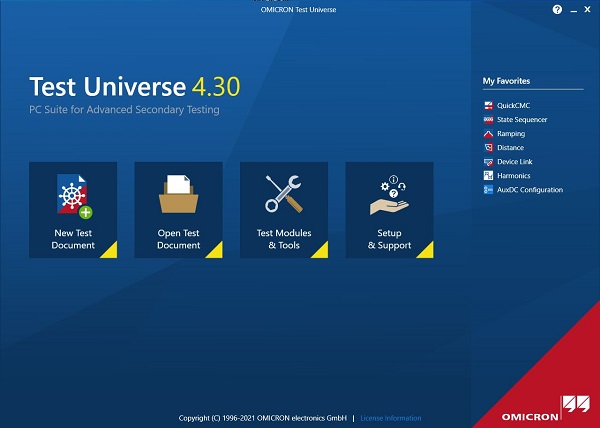
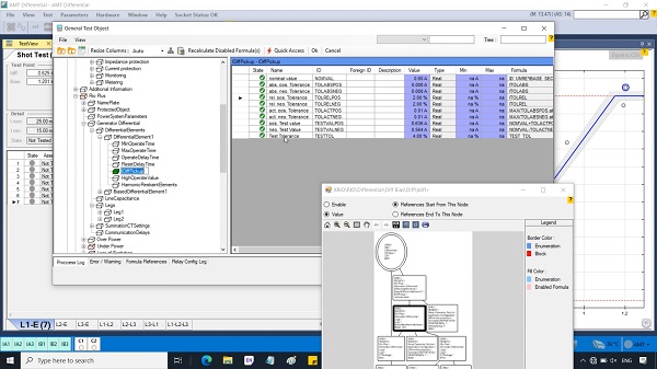
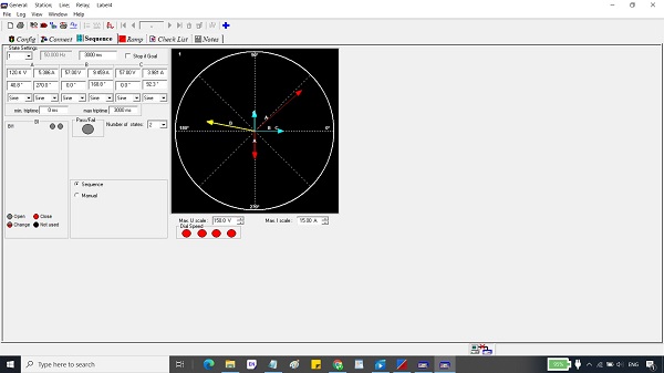
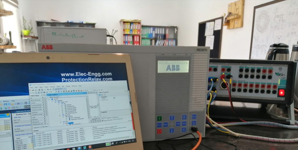
The testing & commissioning of the protection relays can be done by different testing software and hardware. In this training, we have used OMICRON Test Universe, Vebko AMpro, and FREJA win.
Need some experience people to join KBR-AMCDE, Oil and Gas, Al-Khobar, Saudi Arabia
KBR-AMCDE is an entity formed to carry out general engineering and project management services under the Saudi Arabian Oil Company (Saudi Aramco) General Engineering Services Plus (GES+) initiative. KBR AMCDE provides front-end engineering and design (FEED), detailed design, procurement and project management services within the Oil & Gas industry. KBR-AMCDE specializes in front-end engineering design (FEED), detailed design, material procurement, and project management services (PMS). With extensive resources and technology, we deliver quality engineering packages to clients in Kingdom and overseas.
If you are qualified and experienced in PSCAD, please contact Mr. Narayanan Sivakumar with the below details:
Linkedin profile: linkedin.com/in/narayanan-sivakumar-95b80515
Email ID: narayanansivakumar1985@gmail.com
SIEMENS 7UT85 configuration
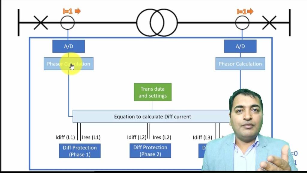
How to enroll in this training course (How to access transformer protection training course):
1- Check out the Transformer Protection Training with the below link (https://elec-engg.com/product/transformer-protection-training/)
2- we will complete your order by sending your license to access the videos (https://elec-engg.com/how-to-access-our-training-courses/)
ِDemo is available
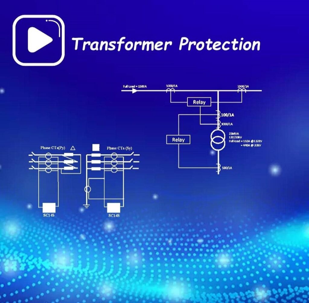
Course details and samples on: https://elec-engg.com/transformer-protection-training-video/

Overview
The IEC 61850 source code library allows a fast and cost-efficient implementation of the IEC 61850 protocols (MMS, GOOSE, Sampled Values) into devices and applications. The APIs are designed to be very easy to use. The basic library is written in C (C99 compliant to provide maximum portability). Due to its hardware and platform-independent design, it can quickly deploy on any platform.
C#.NET Component
The C# library allows the creation of a managed DLL component that can easily be deployed in .NET applications. It is a wrapper of the C library. It can be used to be integrated into GUI applications, SCADA systems …
Features Source Code Library
Source codes that you see in this package:
Application That can create with this library:
Easy programming and development of Scada and Monitoring System for protection Relays and other devices that compatible with IEC 61850 Standard with this package

In this course, you will learn the principles of IEC 61850 programming and building monitoring and SCADA systems for networks that use IEC 61850 protection relays or IEDs (Intelligent Electronic Devices). To do so, first, you will learn about the IEC 61850 standard, including the concept of this standard, the simulation of the IEC 61850 GOOSE, and the IEC 61850 MMS reports. And how to read or write data and control commands to IEDs.
Next, you will learn Programming in IEC61850 Standard. In this chapter, you will learn how to use the IEC61850 Libraries for Programming in C# Language which are prepared by us and attached to the course as a gift. Then you will learn how to write a code for discovering and reading the substation IEDs, Functions, and Data Models. After that, you will learn how to write code to create DataSet and Report from the Data Models and set trigger options.
Learn programming SCADA software based on IEC 61850 for your station as you like!
The IEC 61850 source code library allows a fast and cost-efficient implementation of the IEC 61850 protocols (MMS, GOOSE, Sampled Values) into devices and applications. The APIs are designed to be very easy to use. The basic library is written in C (C99 compliant to provide maximum portability). Due to its hardware and platform-independent design, it can quickly deploy on any platform.
The C# library allows the creation of a managed DLL component that can easily be deployed in .NET applications. It is a wrapper of the C library. It can be used to be integrated into GUI applications, SCADA systems …

Features Source Code Library
Source codes that you see in this package:
Application that can be created with this library:
Easy programming and development of Scada and Monitoring System for protection Relays and other devices that compatible with IEC 61850 Standard with this package
Topics:
working with SIPROTEC 5 multifunction relay IED 7SX800
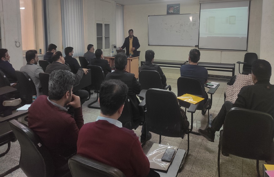

Information
Note: This course can also be held either Online or Face to face based on the request
More info and update about this course: Contac us

Library Global DIGSI 5 Library was opened
Project SaeedRoostaee_digsi5training opened
Analyzed compatibility information
6MU85 configuration requires 0 function points
Starting import of function chart(s) (CFC) from file C:\User
Importing log messages for function chart (CFC) Group warning,
Importing log messages for function chart (CFC) Process mode inactive,
Successfully finished importing
Analyzed software part.,7/27/2023,10:08:10 AM
Line Mode has no settings, so it is not listed under Settings. It is displayed in the Single-line configuration, Communication mapping, and Information routing.,7/27/2023,10:08:16 AM
DIGSI has no settings, so it is not listed under Settings. It is displayed in the Single-line configuration, Communication mapping, and Information routing.,7/27/2023,10:08:17 AM
Web UI has no settings, so it is not listed under Settings. It is displayed in the Single-line configuration, Communication mapping, and Information routing.
Analyzed compatibility information.,7/27/2023,10:09:11 AM
6MU85 configuration requires 0 function points.,7/27/2023,10:09:11 AM
6MU85 configuration requires 0 function points.,7/27/2023,10:09:11 AM
Starting import of function chart(s) (CFC) from file C:\Users\LENOVO\AppData\Local\Temp\3vawjx0o.yc3.tmp into device 6MU85.,7/27/2023,10:09:24 AM
Importing log messages for function chart (CFC) Group warning,7/27/2023,10:09:24 AM
Importing log messages for function chart (CFC) Process mode inactive,7/27/2023,10:09:24 AM
Successfully finished importing.,7/27/2023,10:09:24 AM
Analyzed software part.,7/27/2023,10:09:25 AM
Due to a change in hardware, 1 routing was deleted.,7/27/2023,10:09:28 AM
Line Mode has no settings, so it is not listed under Settings. It is displayed in the Single-line configuration, Communication mapping, and Information routing.,7/27/2023,10:09:32 AM
DIGSI has no settings, so it is not listed under Settings. It is displayed in the Single-line configuration, Communication mapping and Information routing.,7/27/2023,10:09:32 AM
Web UI has no settings, so it is not listed under Settings. It is displayed in the Single-line configuration, Communication mapping and Information routing.,7/27/2023,10:09:33 AM
Analyzed compatibility information.,7/27/2023,10:10:07 AM
6MU85 configuration requires 0 function points.
6MU85 configuration requires 0 function points.,7/27/2023,10:10:07 AM
Starting import of function chart(s) (CFC) from file C:\Users\LENOVO\AppData\Local\Temp\u2zboyex.sai.tmp into device 6MU85.,7/27/2023,10:10:21 AM
Importing log messages for function chart (CFC) Group warning,7/27/2023,10:10:21 AM
Importing log messages for function chart (CFC) Process mode inactive,7/27/2023,10:10:21 AM
Successfully finished importing.,7/27/2023,10:10:22 AM
6MU85 configuration requires 20 function points.,7/27/2023,10:10:22 AM
Analyzed software part.,7/27/2023,10:10:22 AM
Due to change in hardware, 1 routings were deleted.,7/27/2023,10:10:25 AM
Line Mode has no settings, so it is not listed under Settings. It is displayed in the Single-line configuration, Communication mapping and Information routing.,7/27/2023,10:10:29 AM
DIGSI has no settings, so it is not listed under Settings. It is displayed in the Single-line configuration, Communication mapping and Information routing.,7/27/2023,10:10:30 AM
Web UI has no settings, so it is not listed under Settings. It is displayed in the Single-line configuration, Communication mapping and Information routing.,7/27/2023,10:10:30 AM
Analyzed compatibility information.,7/27/2023,10:11:01 AM
6MU85 configuration requires 0 function points.,7/27/2023,10:11:01 AM
6MU85 configuration requires 0 function points.,7/27/2023,10:11:01 AM
Starting import of function chart(s) (CFC) from file C:\Users\LENOVO\AppData\Local\Temp\i5dxb3f4.p3z.tmp into device 6MU85.,7/27/2023,10:11:11 AM
Importing log messages for function chart (CFC) Group warning,7/27/2023,10:11:11 AM
Importing log messages for function chart (CFC) Process mode inactive,7/27/2023,10:11:11 AM
Successfully finished importing.,7/27/2023,10:11:11 AM
Analyzed software part.,7/27/2023,10:11:12 AM
Line Mode has no settings, so it is not listed under Settings. It is displayed in the Single-line configuration, Communication mapping and Information routing.,7/27/2023,10:11:17 AM
DIGSI has no settings, so it is not listed under Settings. It is displayed in the Single-line configuration, Communication mapping and Information routing.,7/27/2023,10:11:18 AM
Web UI has no settings, so it is not listed under Settings. It is displayed in the Single-line configuration, Communication mapping and Information routing.,7/27/2023,10:11:18 AM
Analyzed compatibility information.,7/27/2023,10:11:50 AM
6MU85 configuration requires 0 function points.,7/27/2023,10:11:50 AM
6MU85 configuration requires 0 function points.,7/27/2023,10:11:50 AM
Starting import of function chart(s) (CFC) from file C:\Users\LENOVO\AppData\Local\Temp\kd145sd3.5vv.tmp into device 6MU85.
Importing log messages for function chart (CFC) Group warning
Importing log messages for function chart (CFC) Process mode inactive,
Successfully finished importing.,7/27/2023,10:11:57 AM
Analyzed software part.
Line Mode has no settings, so it is not listed under Settings. It is displayed in the Single-line configuration, Communication mapping and Information routing.,7/27/2023,10:12:01 AM
DIGSI has no settings, so it is not listed under Settings. It is displayed in the Single-line configuration, Communication mapping and Information routing.,7/27/2023,10:12:02 AM
Web UI has no settings, so it is not listed under Settings. It is displayed in the Single-line configuration, Communication mapping and Information routing.,7/27/2023,10:12:02 AM
Function-chart (CFC) compilation,7/27/2023,10:13:01 AM
The project SaeedRoostaee_digsi5training was saved successfully.,7/27/2023,10:15:57 AM
Analyzed compatibility information.,7/27/2023,10:16:38 AM
7UM85 configuration requires 0 function points.,7/27/2023,10:16:38 AM
7UM85 configuration requires 0 function points.,7/27/2023,10:16:38 AM
Starting import of function chart(s) (CFC) from file C:\Users\LENOVO\AppData\Local\Temp\4fklxd5f.hx1.tmp into device 7UM85.,7/27/2023,10:16:59 AM
Analyzed software part.,7/27/2023,10:17:01 AM
Analyzed compatibility information.,7/27/2023,10:18:41 AM
7UM85 configuration requires 0 function points.,7/27/2023,10:18:41 AM
7UM85 configuration requires 0 function points.,7/27/2023,10:18:41 AM
Starting import of function chart(s) (CFC) from file C:\Users\LENOVO\AppData\Local\Temp\q1grapr5.1rp.tmp into device 7UM85.,7/27/2023,10:19:05 AM
Importing log messages for function chart (CFC) Group warning,7/27/2023,10:19:05 AM
Importing log messages for function chart (CFC) Process mode inactive,7/27/2023,10:19:05 AM
Successfully finished importing.,7/27/2023,10:19:05 AM
7UM85 configuration requires 85 function points.,7/27/2023,10:19:06 AM
Analyzed software part.,7/27/2023,10:19:06 AM
Analyzed compatibility information.,7/27/2023,10:20:28 AM
7UM85 configuration requires 0 function points.,7/27/2023,10:20:28 AM
7UM85 configuration requires 0 function points.,7/27/2023,10:20:28 AM
Starting import of function chart(s) (CFC) from file C:\Users\LENOVO\AppData\Local\Temp\1e0gnksz.mfz.tmp into device 7UM85.,7/27/2023,10:20:55 AM
Importing log messages for function chart (CFC) Group warning,7/27/2023,10:20:55 AM
Importing log messages for function chart (CFC) Process mode inactive,7/27/2023,10:20:55 AM
Successfully finished importing.,7/27/2023,10:20:55 AM
7UM85 configuration requires 105 function points.,7/27/2023,10:20:56 AM
Analyzed software part.,7/27/2023,10:20:56 AM
Analyzed compatibility information.,7/27/2023,10:21:48 AM
7UM85 configuration requires 0 function points.,7/27/2023,10:21:48 AM
7UM85 configuration requires 0 function points.,7/27/2023,10:21:48 AM
Starting import of function chart(s) (CFC) from file C:\Users\LENOVO\AppData\Local\Temp\yzrziyf1.5ct.tmp into device 7UM85.,7/27/2023,10:22:26 AM
Importing log messages for function chart (CFC) Group warning,7/27/2023,10:22:26 AM
Importing log messages for function chart (CFC) Process mode inactive,7/27/2023,10:22:26 AM
Successfully finished importing.,7/27/2023,10:22:26 AM
7UM85 configuration requires 330 function points.,7/27/2023,10:22:27 AM
Analyzed software part.,7/27/2023,10:22:29 AM
Analyzed compatibility information.,7/27/2023,10:23:24 AM
7UM85 configuration requires 0 function points.,7/27/2023,10:23:24 AM
7UM85 configuration requires 0 function points.,7/27/2023,10:23:24 AM
Starting import of function chart(s) (CFC) from file C:\Users\LENOVO\AppData\Local\Temp\g5ojtdjt.axj.tmp into device 7UM85.,7/27/2023,10:23:53 AM
Importing log messages for function chart (CFC) Group warning,7/27/2023,10:23:53 AM
Importing log messages for function chart (CFC) Process mode inactive,7/27/2023,10:23:54 AM
Successfully finished importing.,7/27/2023,10:23:54 AM
7UM85 configuration requires 255 function points.,7/27/2023,10:23:55 AM
Analyzed software part.,7/27/2023,10:23:55 AM
The project SaeedRoostaee_digsi5training was saved successfully.,7/27/2023,10:25:01 AM
Analyzed compatibility information.,7/27/2023,10:26:38 AM
7VU85 configuration requires 0 function points.,7/27/2023,10:26:38 AM
7VU85 configuration requires 0 function points.,7/27/2023,10:26:38 AM
Starting import of function chart(s) (CFC) from file C:\Users\LENOVO\AppData\Local\Temp\htzmdc0f.3i1.tmp into device 7VU85.,7/27/2023,10:26:56 AM
Importing log messages for function chart (CFC) Group warning,7/27/2023,10:26:56 AM
Importing log messages for function chart (CFC) Process mode inactive,7/27/2023,10:26:56 AM
Successfully finished importing.,7/27/2023,10:26:57 AM
Analyzed software part.,7/27/2023,10:26:57 AM
Analyzed compatibility information.,7/27/2023,10:27:59 AM
7VU85 configuration requires 0 function points.,7/27/2023,10:27:59 AM
7VU85 configuration requires 0 function points.,7/27/2023,10:27:59 AM
Starting import of function chart(s) (CFC) from file C:\Users\LENOVO\AppData\Local\Temp\djy2bv1q.rly.tmp into device 7VU85.,7/27/2023,10:28:29 AM
Importing log messages for function chart (CFC) Group warning,7/27/2023,10:28:29 AM
Importing log messages for function chart (CFC) Process mode inactive,7/27/2023,10:28:30 AM
Successfully finished importing.,7/27/2023,10:28:30 AM
7VU85 configuration requires 470 function points.,7/27/2023,10:28:31 AM
Analyzed software part.,7/27/2023,10:28:32 AM
Analyzed compatibility information.,7/27/2023,10:29:16 AM
7VU85 configuration requires 0 function points.,7/27/2023,10:29:16 AM
7VU85 configuration requires 0 function points.,7/27/2023,10:29:16 AM
Starting import of function chart(s) (CFC) from file C:\Users\LENOVO\AppData\Local\Temp\drdplp2d.gqq.tmp into device 7VU85.,7/27/2023,10:29:44 AM
Importing log messages for function chart (CFC) Group warning,7/27/2023,10:29:44 AM
Importing log messages for function chart (CFC) Process mode inactive,7/27/2023,10:29:45 AM
Successfully finished importing.,7/27/2023,10:29:45 AM
7VU85 configuration requires 400 function points.,7/27/2023,10:29:45 AM
Analyzed software part.,7/27/2023,10:29:46 AM
The project SaeedRoostaee_digsi5training was saved successfully.,7/27/2023,10:30:09 AM
The project SaeedRoostaee_digsi5training was saved successfully.,7/27/2023,10:30:47 AM
Analyzed compatibility information.,7/27/2023,10:32:33 AM
7VE85 configuration requires 0 function points.,7/27/2023,10:32:33 AM
7VE85 configuration requires 0 function points.,7/27/2023,10:32:33 AM
Starting import of function chart(s) (CFC) from file C:\Users\LENOVO\AppData\Local\Temp\4ynlrvko.squ.tmp into device 7VE85.,7/27/2023,10:32:46 AM
Importing log messages for function chart (CFC) Group warning,7/27/2023,10:32:46 AM
Importing log messages for function chart (CFC) Process mode inactive,7/27/2023,10:32:46 AM
Successfully finished importing.,7/27/2023,10:32:46 AM
Analyzed software part.,7/27/2023,10:32:47 AM
Analyzed compatibility information.,7/27/2023,10:33:33 AM
7VE85 configuration requires 0 function points.,7/27/2023,10:33:33 AM
7VE85 configuration requires 0 function points.,7/27/2023,10:33:33 AM
Starting import of function chart(s) (CFC) from file C:\Users\LENOVO\AppData\Local\Temp\h4jl3ijd.fox.tmp into device 7VE85.,7/27/2023,10:33:53 AM
Importing log messages for function chart (CFC) Group warning,7/27/2023,10:33:53 AM
Importing log messages for function chart (CFC) Process mode inactive,7/27/2023,10:33:54 AM
Successfully finished importing.,7/27/2023,10:33:54 AM
7VE85 configuration requires 75 function points.,7/27/2023,10:33:54 AM
Analyzed software part.,7/27/2023,10:33:55 AM
Analyzed compatibility information.,7/27/2023,10:34:28 AM
7VE85 configuration requires 0 function points.,7/27/2023,10:34:28 AM
7VE85 configuration requires 0 function points.,7/27/2023,10:34:28 AM
Starting import of function chart(s) (CFC) from file C:\Users\LENOVO\AppData\Local\Temp\rlvnzip1.5zo.tmp into device 7VE85.,7/27/2023,10:34:44 AM
Importing log messages for function chart (CFC) Group warning,7/27/2023,10:34:44 AM
Importing log messages for function chart (CFC) Process mode inactive,7/27/2023,10:34:45 AM
Successfully finished importing.,7/27/2023,10:34:45 AM
7VE85 configuration requires 115 function points.,7/27/2023,10:34:46 AM
Analyzed software part.,7/27/2023,10:34:47 AM
Analyzed compatibility information.,7/27/2023,10:35:58 AM
7VE85 configuration requires 0 function points.,7/27/2023,10:35:58 AM
7VE85 configuration requires 0 function points.,7/27/2023,10:35:58 AM
Starting import of function chart(s) (CFC) from file C:\Users\LENOVO\AppData\Local\Temp\d1etzmsn.mav.tmp into device 7VE85.,7/27/2023,10:36:15 AM
Importing log messages for function chart (CFC) Group warning,7/27/2023,10:36:15 AM
Importing log messages for function chart (CFC) Process mode inactive,7/27/2023,10:36:15 AM
Successfully finished importing.,7/27/2023,10:36:15 AM
7VE85 configuration requires 115 function points.,7/27/2023,10:36:16 AM
Analyzed software part.,7/27/2023,10:36:17 AM
Analyzed compatibility information.,7/27/2023,10:37:18 AM
7VE85 configuration requires 0 function points.,7/27/2023,10:37:18 AM
7VE85 configuration requires 0 function points.,7/27/2023,10:37:18 AM
Starting import of function chart(s) (CFC) from file C:\Users\LENOVO\AppData\Local\Temp\hysu15dy.clo.tmp into device 7VE85.,7/27/2023,10:37:41 AM
Importing log messages for function chart (CFC) Group warning,7/27/2023,10:37:41 AM
Importing log messages for function chart (CFC) Process mode inactive,7/27/2023,10:37:41 AM
Importing log messages for function chart (CFC) VoltageSelection,7/27/2023,10:37:41 AM
Successfully finished importing.,7/27/2023,10:37:42 AM
7VE85 configuration requires 115 function points.,7/27/2023,10:37:42 AM
Analyzed software part.,7/27/2023,10:37:42 AM
Analyzed compatibility information.,7/27/2023,10:38:47 AM
7VE85 configuration requires 0 function points.,7/27/2023,10:38:47 AM
7VE85 configuration requires 0 function points.,7/27/2023,10:38:47 AM
Starting import of function chart(s) (CFC) from file C:\Users\LENOVO\AppData\Local\Temp\c0jkcjzm.ff4.tmp into device 7VE85.,7/27/2023,10:39:13 AM
Importing log messages for function chart (CFC) Group warning,7/27/2023,10:39:13 AM
Importing log messages for function chart (CFC) Process mode inactive,7/27/2023,10:39:14 AM
Successfully finished importing.,7/27/2023,10:39:14 AM
7VE85 configuration requires 230 function points.,7/27/2023,10:39:14 AM
Analyzed software part.,7/27/2023,10:39:15 AM
Due to change in hardware, 15 routings were deleted.,7/27/2023,10:39:21 AM
The project SaeedRoostaee_digsi5training was saved successfully.,7/27/2023,10:40:17 AM
Analyzed compatibility information.,7/27/2023,10:42:05 AM
7SX85 configuration requires 0 function points.,7/27/2023,10:42:05 AM
7SX85 configuration requires 0 function points.,7/27/2023,10:42:05 AM
Starting import of function chart(s) (CFC) from file C:\Users\LENOVO\AppData\Local\Temp\rwtxsokr.dq5.tmp into device 7SX85.,7/27/2023,10:42:24 AM
7SX85 configuration requires 74 function points.,7/27/2023,10:42:25 AM
Analyzed software part.,7/27/2023,10:42:26 AM
Analyzed compatibility information.,7/27/2023,10:43:04 AM
7SX85 configuration requires 0 function points.,7/27/2023,10:43:04 AM
7SX85 configuration requires 0 function points.,7/27/2023,10:43:04 AM
Starting import of function chart(s) (CFC) from file C:\Users\LENOVO\AppData\Local\Temp\bhr4svo1.p0w.tmp into device 7SX85.,7/27/2023,10:43:27 AM
7SX85 configuration requires 126 function points.,7/27/2023,10:43:27 AM
Analyzed software part.,7/27/2023,10:43:28 AM
The project SaeedRoostaee_digsi5training was saved successfully.,7/27/2023,10:44:17 AM
Analyzed compatibility information.,7/27/2023,11:00:39 AM
6MD86 configuration requires 0 function points.,7/27/2023,11:00:39 AM
6MD86 configuration requires 0 function points.,7/27/2023,11:00:40 AM
Analyzed software part.,7/27/2023,11:00:46 AM
Analyzed compatibility information.,7/27/2023,11:01:09 AM
6MD86_1 configuration requires 0 function points.,7/27/2023,11:01:09 AM
6MD86_1 configuration requires 0 function points.,7/27/2023,11:01:09 AM
Starting import of function chart(s) (CFC) from file C:\Users\LENOVO\AppData\Local\Temp\oua4evsi.ttf.tmp into device 6MD86_1.,7/27/2023,11:01:28 AM
Analyzed software part.,7/27/2023,11:01:30 AM
Analyzed compatibility information.,7/27/2023,11:02:29 AM
6MD86 configuration requires 0 function points.,7/27/2023,11:02:29 AM
6MD86 configuration requires 0 function points.,7/27/2023,11:02:29 AM
Starting import of function chart(s) (CFC) from file C:\Users\LENOVO\AppData\Local\Temp\erexcpgi.y4l.tmp into device 6MD86.,7/27/2023,11:03:15 AM
Analyzed software part.,7/27/2023,11:03:20 AM
Due to change in hardware, 29 routings were deleted.,7/27/2023,11:03:32 AM
Analyzed compatibility information.,7/27/2023,11:04:08 AM
6MD86 configuration requires 0 function points.,7/27/2023,11:04:08 AM
6MD86 configuration requires 0 function points.,7/27/2023,11:04:08 AM
Starting import of function chart(s) (CFC) from file C:\Users\LENOVO\AppData\Local\Temp\vowhsuzk.axy.tmp into device 6MD86.,7/27/2023,11:04:48 AM
6MD86 configuration requires 60 function points.,7/27/2023,11:04:50 AM
Analyzed software part.,7/27/2023,11:04:51 AM
Due to change in hardware, 23 routings were deleted.,7/27/2023,11:05:00 AM
Analyzed compatibility information.,7/27/2023,11:06:19 AM
6MD86 configuration requires 0 function points.,7/27/2023,11:06:19 AM
6MD86 configuration requires 0 function points.,7/27/2023,11:06:19 AM
Starting import of function chart(s) (CFC) from file C:\Users\LENOVO\AppData\Local\Temp\wojcjuzy.cux.tmp into device 6MD86.,7/27/2023,11:06:36 AM
Importing log messages for function chart (CFC) GRPWARN_POW,7/27/2023,11:06:36 AM
Importing log messages for function chart (CFC) PROCESS_MODE_INACTIVE,7/27/2023,11:06:36 AM
Successfully finished importing.,7/27/2023,11:06:36 AM
6MD86 configuration requires 200 function points.,7/27/2023,11:06:37 AM
Analyzed software part.,7/27/2023,11:06:37 AM
Analyzed compatibility information.,7/27/2023,11:25:01 AM
7UT87 configuration requires 0 function points.,7/27/2023,11:25:01 AM
7UT87 configuration requires 0 function points.,7/27/2023,11:25:01 AM
Starting import of function chart(s) (CFC) from file C:\Users\LENOVO\AppData\Local\Temp\fk53a1ei.qb0.tmp into device 7UT87.,7/27/2023,11:25:20 AM
Importing log messages for function chart (CFC) Group warning,7/27/2023,11:25:20 AM
Importing log messages for function chart (CFC) Process mode inactive,7/27/2023,11:25:21 AM
Successfully finished importing.,7/27/2023,11:25:21 AM
Analyzed software part.,7/27/2023,11:25:22 AM
Analyzed compatibility information.,7/27/2023,11:26:30 AM
7UT87 configuration requires 0 function points.,7/27/2023,11:26:30 AM
7UT87 configuration requires 0 function points.,7/27/2023,11:26:30 AM
Starting import of function chart(s) (CFC) from file C:\Users\LENOVO\AppData\Local\Temp\4h5nmjbt.upq.tmp into device 7UT87.,7/27/2023,11:26:54 AM
Importing log messages for function chart (CFC) Group warning,7/27/2023,11:26:54 AM
Importing log messages for function chart (CFC) Process mode inactive,7/27/2023,11:26:54 AM
Successfully finished importing.,7/27/2023,11:26:55 AM
7UT87 configuration requires 25 function points.,7/27/2023,11:26:55 AM
Analyzed software part.,7/27/2023,11:26:56 AM
Analyzed compatibility information.,7/27/2023,11:28:30 AM
7UT87 configuration requires 0 function points.,7/27/2023,11:28:30 AM
7UT87 configuration requires 0 function points.,7/27/2023,11:28:30 AM
Starting import of function chart(s) (CFC) from file
SIPROTEC 5 and DIGSI 5 training by Dr. Saeed Roostaee
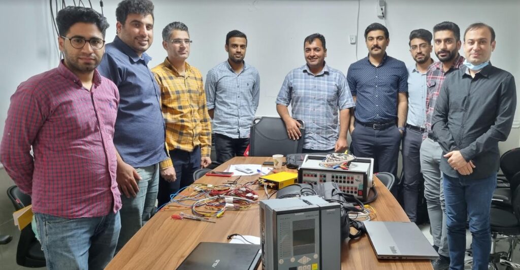
C:\Users\LENOVO\AppData\Local\Temp\zf1oyw44.fey.tmp into device 7UT87.,7/27/2023,11:28:58 AM
Importing log messages for function chart (CFC) Group warning,7/27/2023,11:28:58 AM
Importing log messages for function chart (CFC) Process mode inactive,7/27/2023,11:28:58 AM
Successfully finished importing.,7/27/2023,11:28:59 AM
7UT87 configuration requires 30 function points.,7/27/2023,11:28:59 AM
Analyzed software part.,7/27/2023,11:29:00 AM
Analyzed compatibility information.,7/27/2023,11:29:41 AM
7UT87 configuration requires 0 function points.,7/27/2023,11:29:42 AM
7UT87 configuration requires 0 function points.,7/27/2023,11:29:42 AM
Starting import of function chart(s) (CFC) from file C:\Users\LENOVO\AppData\Local\Temp\kocertsc.mb2.tmp into device 7UT87.,7/27/2023,11:30:10 AM
Importing log messages for function chart (CFC) Group warning,7/27/2023,11:30:10 AM
Importing log messages for function chart (CFC) Process mode inactive,7/27/2023,11:30:11 AM
Successfully finished importing.,7/27/2023,11:30:11 AM
7UT87 configuration requires 170 function points.,7/27/2023,11:30:11 AM
Analyzed software part.,7/27/2023,11:30:12 AM
Analyzed compatibility information.,7/27/2023,11:30:46 AM
7UT87 configuration requires 0 function points.,7/27/2023,11:30:46 AM
7UT87 configuration requires 0 function points.,7/27/2023,11:30:46 AM
Starting import of function chart(s) (CFC) from file C:\Users\LENOVO\AppData\Local\Temp\g1vz3iv4.n3x.tmp into device 7UT87.,7/27/2023,11:31:13 AM
Importing log messages for function chart (CFC) Group warning,7/27/2023,11:31:13 AM
Importing log messages for function chart (CFC) Process mode inactive,7/27/2023,11:31:13 AM
Successfully finished importing.,7/27/2023,11:31:13 AM
7UT87 configuration requires 50 function points.,7/27/2023,11:31:14 AM
Analyzed software part.,7/27/2023,11:31:14 AM
Analyzed compatibility information.,7/27/2023,11:31:47 AM
7UT87 configuration requires 0 function points.,7/27/2023,11:31:47 AM
7UT87 configuration requires 0 function points.,7/27/2023,11:31:47 AM
Starting import of function chart(s) (CFC) from file C:\Users\LENOVO\AppData\Local\Temp\mueys0vx.wkm.tmp into device 7UT87.,7/27/2023,11:32:14 AM
Importing log messages for function chart (CFC) Group warning,7/27/2023,11:32:14 AM
Importing log messages for function chart (CFC) Process mode inactive,7/27/2023,11:32:15 AM
Successfully finished importing.,7/27/2023,11:32:16 AM
Analyzed software part.,7/27/2023,11:32:17 AM
Analyzed compatibility information.,7/27/2023,11:33:01 AM
7UT87 configuration requires 0 function points.,7/27/2023,11:33:01 AM
7UT87 configuration requires 0 function points.,7/27/2023,11:33:01 AM
Starting import of function chart(s) (CFC) from file C:\Users\LENOVO\AppData\Local\Temp\o2l40wo1.1qd.tmp into device 7UT87.,7/27/2023,11:33:39 AM
Importing log messages for function chart (CFC) Group warning,7/27/2023,11:33:39 AM
Importing log messages for function chart (CFC) Process mode inactive,7/27/2023,11:33:40 AM
Successfully finished importing.,7/27/2023,11:33:40 AM
7UT87 configuration requires 45 function points.,7/27/2023,11:33:40 AM
Analyzed software part.,7/27/2023,11:33:41 AM
Analyzed compatibility information.,7/27/2023,11:34:32 AM
7UT87 configuration requires 0 function points.,7/27/2023,11:34:32 AM
7UT87 configuration requires 0 function points.,7/27/2023,11:34:32 AM
Starting import of function chart(s) (CFC) from file C:\Users\LENOVO\AppData\Local\Temp\bx5kvvoj.idx.tmp into device 7UT87.,7/27/2023,11:35:16 AM
Importing log messages for function chart (CFC) Group warning,7/27/2023,11:35:16 AM
Importing log messages for function chart (CFC) Process mode inactive,7/27/2023,11:35:16 AM
Importing log messages for function chart (CFC) DIS_Z4_trip_all_CB,7/27/2023,11:35:16 AM
Successfully finished importing.,7/27/2023,11:35:16 AM
7UT87 configuration requires 150 function points.,7/27/2023,11:35:17 AM
Analyzed software part.,7/27/2023,11:35:19 AM
Analyzed compatibility information.,7/27/2023,11:39:39 AM
7UT87 configuration requires 0 function points.,7/27/2023,11:39:39 AM
7UT87 configuration requires 0 function points.,7/27/2023,11:39:39 AM
Starting import of function chart(s) (CFC) from file C:\Users\LENOVO\AppData\Local\Temp\nwlj1jve.e4e.tmp into device 7UT87.,7/27/2023,11:40:12 AM
Importing log messages for function chart (CFC) Group warning,7/27/2023,11:40:12 AM
Importing log messages for function chart (CFC) Process mode inactive,7/27/2023,11:40:13 AM
Successfully finished importing.,7/27/2023,11:40:13 AM
7UT87 configuration requires 30 function points.,7/27/2023,11:40:13 AM
Analyzed software part.,7/27/2023,11:40:14 AM
Analyzed compatibility information.,7/27/2023,11:41:13 AM
7UT87 configuration requires 0 function points.,7/27/2023,11:41:13 AM
7UT87 configuration requires 0 function points.,7/27/2023,11:41:13 AM
Starting import of function chart(s) (CFC) from file C:\Users\LENOVO\AppData\Local\Temp\s20dfpoq.2kd.tmp into device 7UT87.,7/27/2023,11:41:59 AM
Importing log messages for function chart (CFC) Group warning,7/27/2023,11:41:59 AM
Importing log messages for function chart (CFC) Process mode inactive,7/27/2023,11:42:00 AM
Successfully finished importing.,7/27/2023,11:42:00 AM
7UT87 configuration requires 30 function points.,7/27/2023,11:42:01 AM
Analyzed software part.,7/27/2023,11:42:02 AM
Assignment of offline configuration 7UT87_3_2W 1.5 to another offline configuration 7UT87_1_2W basic is not possible. Assign always online devices to offline configurations.,7/27/2023,11:43:08 AM
The project SaeedRoostaee_digsi5training was saved successfully.,7/27/2023,11:43:56 AM
Analyzed compatibility information.,7/27/2023,11:45:51 AM
7SS85 configuration requires 0 function points.,7/27/2023,11:45:51 AM
7SS85 configuration requires 0 function points.,7/27/2023,11:45:51 AM
Starting import of function chart(s) (CFC) from file
C:\Users\LENOVO\AppData\Local\Temp\1lwlt0co.g3s.tmp into device 7SS85.,7/27/2023,11:46:01 AM
Importing log messages for function chart (CFC) Group warning,7/27/2023,11:46:01 AM
Importing log messages for function chart (CFC) Process mode inactive,7/27/2023,11:46:01 AM
Successfully finished importing.,7/27/2023,11:46:01 AM
Analyzed software part.,7/27/2023,11:46:01 AM
Analyzed compatibility information.,7/27/2023,11:46:52 AM
7VK87 configuration requires 0 function points.,7/27/2023,11:46:52 AM
7VK87 configuration requires 0 function points.,7/27/2023,11:46:52 AM
Starting import of function chart(s) (CFC) from file C:\Users\LENOVO\AppData\Local\Temp\gpn2w0ns.wbw.tmp into device 7VK87.,7/27/2023,11:47:13 AM
Importing log messages for function chart (CFC) Group warning,7/27/2023,11:47:13 AM
Importing log messages for function chart (CFC) Process mode inactive,7/27/2023,11:47:14 AM
Successfully finished importing.,7/27/2023,11:47:14 AM
Analyzed software part.,7/27/2023,11:47:15 AM
Analyzed compatibility information.,7/27/2023,11:48:11 AM
7SL87 configuration requires 0 function points.,7/27/2023,11:48:11 AM
7SL87 configuration requires 0 function points.,7/27/2023,11:48:11 AM
Starting import of function chart(s) (CFC) from file C:\Users\LENOVO\AppData\Local\Temp\by51qi0y.yx1.tmp into device 7SL87.,7/27/2023,11:48:32 AM
Importing log messages for function chart (CFC) Group warning,7/27/2023,11:48:32 AM
Importing log messages for function chart (CFC) Process mode inactive,7/27/2023,11:48:33 AM
Successfully finished importing.,7/27/2023,11:48:33 AM
Analyzed software part.,7/27/2023,11:48:34 AM
Analyzed compatibility information.,7/27/2023,11:49:10 AM
7SL87 configuration requires 0 function points.,7/27/2023,11:49:10 AM
7SL87 configuration requires 0 function points.,7/27/2023,11:49:10 AM
Starting import of function chart(s) (CFC) from file C:\Users\LENOVO\AppData\Local\Temp\ojyjebnh.0lh.tmp into device 7SL87.,7/27/2023,11:49:41 AM
Importing log messages for function chart (CFC) Group warning,7/27/2023,11:49:41 AM
Importing log messages for function chart (CFC) Process mode inactive,7/27/2023,11:49:42 AM
Successfully finished importing.,7/27/2023,11:49:42 AM
7SL87 configuration requires 225 function points.,7/27/2023,11:49:43 AM
Analyzed software part.,7/27/2023,11:49:44 AM
Analyzed compatibility information.,7/27/2023,11:50:19 AM
7SL87 configuration requires 0 function points.,7/27/2023,11:50:19 AM
7SL87 configuration requires 0 function points.,7/27/2023,11:50:20 AM
Starting import of function chart(s) (CFC) from file C:\Users\LENOVO\AppData\Local\Temp\znrrm0rx.ugj.tmp into device 7SL87.,7/27/2023,11:50:59 AM
Importing log messages for function chart (CFC) DISCON_7SL87_7SD87,7/27/2023,11:50:59 AM
Importing log messages for function chart (CFC) Group warning,7/27/2023,11:50:59 AM
Importing log messages for function chart (CFC) Process mode inactive,7/27/2023,11:51:00 AM
Importing log messages for function chart (CFC) RECL_7SX87_1,7/27/2023,11:51:00 AM
Importing log messages for function chart (CFC) RECL_7SX87_2,7/27/2023,11:51:00 AM
Successfully finished importing.,7/27/2023,11:51:01 AM
7SL87 configuration requires 400 function points.,7/27/2023,11:51:01 AM
Analyzed software part.,7/27/2023,11:51:03 AM
The project SaeedRoostaee_digsi5training was saved successfully.,7/27/2023,11:51:57 AM
Analyzed compatibility information.,7/27/2023,11:52:29 AM
7SD87 configuration requires 0 function points.,7/27/2023,11:52:29 AM
7SD87 configuration requires 0 function points.,7/27/2023,11:52:29 AM
Starting import of function chart(s) (CFC) from file C:\Users\LENOVO\AppData\Local\Temp\u2lbfpnj.14x.tmp into device 7SD87.,7/27/2023,11:52:49 AM
Importing log messages for function chart (CFC) Group warning,7/27/2023,11:52:49 AM
Importing log messages for function chart (CFC) Process mode inactive,7/27/2023,11:52:50 AM
Successfully finished importing.,7/27/2023,11:52:50 AM
Analyzed software part.,7/27/2023,11:52:51 AM
Analyzed compatibility information.,7/27/2023,11:53:34 AM
7SD87 configuration requires 0 function points.,7/27/2023,11:53:34 AM
7SD87 configuration requires 0 function points.,7/27/2023,11:53:34 AM
Starting import of function chart(s) (CFC) from file C:\Users\LENOVO\AppData\Local\Temp\ti4eq0z4.04y.tmp into device 7SD87.,7/27/2023,11:53:58 AM
Importing log messages for function chart (CFC) Group warning,7/27/2023,11:53:58 AM
Importing log messages for function chart (CFC) Process mode inactive,7/27/2023,11:53:59 AM
Successfully finished importing.,7/27/2023,11:53:59 AM
7SD87 configuration requires 170 function points.,7/27/2023,11:53:59 AM
Analyzed software part.,7/27/2023,11:54:00 AM
Analyzed compatibility information.,7/27/2023,11:54:43 AM
7SD87 configuration requires 0 function points.,7/27/2023,11:54:43 AM
7SD87 configuration requires 0 function points.,7/27/2023,11:54:43 AM
Starting import of function chart(s) (CFC) from file C:\Users\LENOVO\AppData\Local\Temp\qytlw5aa.tuf.tmp into device 7SD87.,7/27/2023,11:55:18 AM
Importing log messages for function chart (CFC) DISCON_7SL87_7SD87,7/27/2023,11:55:18 AM
Importing log messages for function chart (CFC) Group warning,7/27/2023,11:55:19 AM
Importing log messages for function chart (CFC) Process mode inactive,7/27/2023,11:55:20 AM
Importing log messages for function chart (CFC) RECL_7SX87_1,7/27/2023,11:55:20 AM
Importing log messages for function chart (CFC) RECL_7SX87_2,7/27/2023,11:55:20 AM
Successfully finished importing.,7/27/2023,11:55:21 AM
7SD87 configuration requires 345 function points.
Analyzed software part.,
The project SaeedRoostaee_digsi5training was saved successfully.


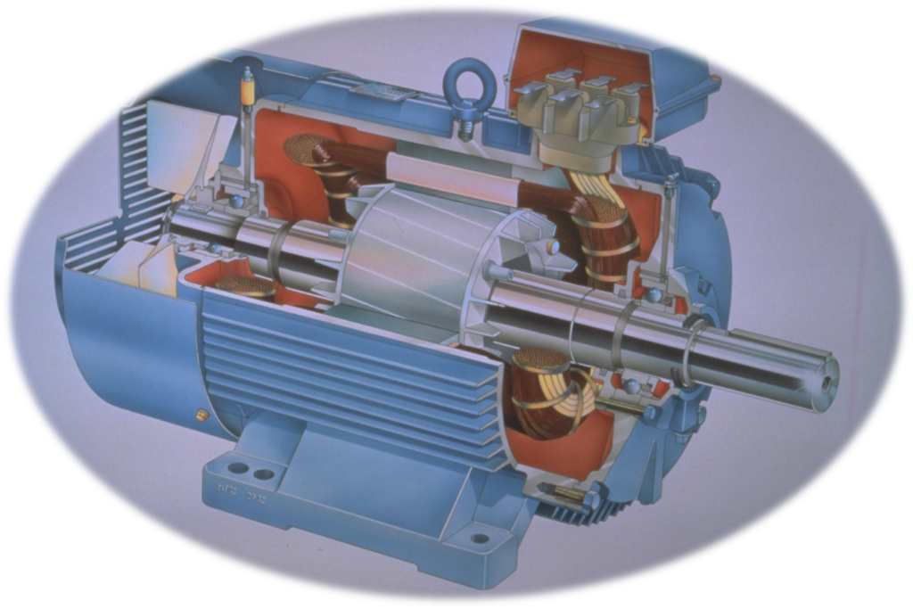
Modern numerical motor relay protection technology must be sufficient to meet the protection requirements of any of the vast range of motor designs. A motor protection relay providing sufficient protection will have the following set of characteristics such as extended start relay protection, loss-of-load relay protection, number of starts limitation, stalling relay protection, short circuit relay protection, thermal relay protection, Earth fault relay protection, negative sequence current detection, winding RTD measurement/trip, under-voltage relay protection, auxiliary supply supervision, …
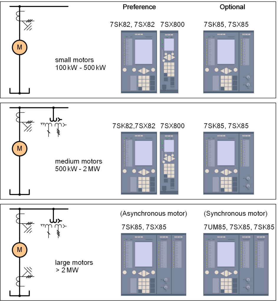
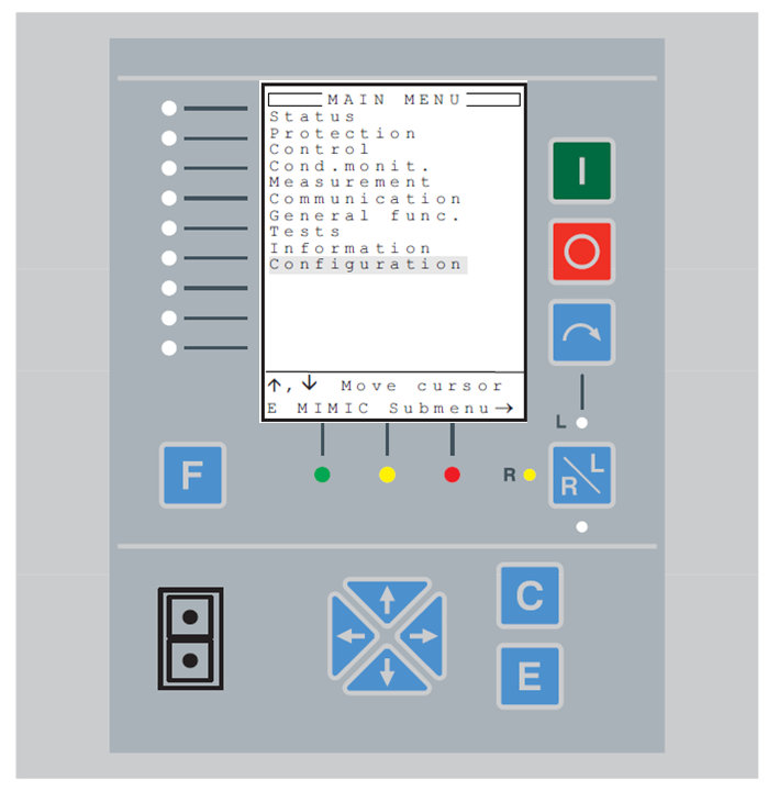
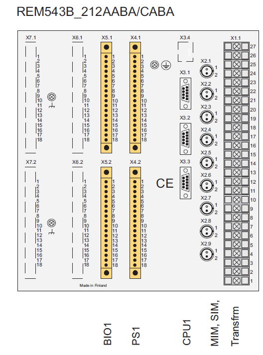
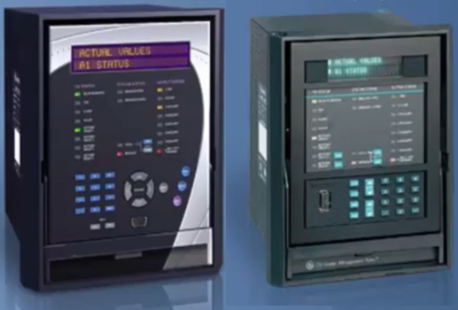
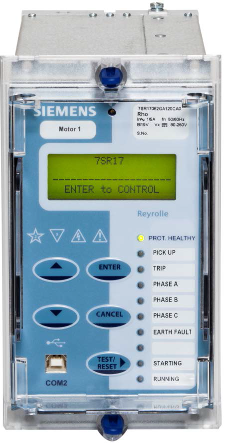

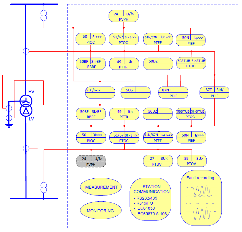

Line differential protection (87L):
The line differential protection consists of three protection functions, phase segregated differential protection function, sudden change current differential protection function and zero sequence current differential protection function.
These three functions are associated with achieving high sensitivity and reliability with capacitive charge current compensation and reliable phase selection during various system disturbances. The precise time
synchronization of sampling ensures the differential protection of both end IEDs to operate reliably
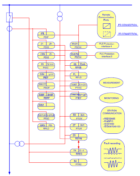
Distance protection (21, 21N)
The transmission line distance protection provides a five zones full scheme protection with all phase to phase faults and phase to earth fault loops independently for each zones.
Additionally, one extension zone is employed to co-operate with Auto-reclosing and tele-protection schemes.
Chapter 1 IED Introduction ………………………………………………………………………………………………… 1
Chapter 2 Local human machine interface ………………………………………………………………………… 3
1 Introduction ……………………………………………………………………………………………………………………… 4
2 Liquid crystal display(LCD) …………………………………………………………………………………………. 6
3 Keyboard ………………………………………………………………………………………………………………………… 7
4 IED menu ………………………………………………………………………………………………………………………… 8
4.1 Menu construction …………………………………………………………………………………………….. 8
4.2 Operation status ……………………………………………………………………………………………….. 9
4.3 Query reports ………………………………………………………………………………………………….. 10
4.4 Set time …………………………………………………………………………………………………………… 10
4.5 Contrast ………………………………………………………………………………………………………….. 10
4.6 Settings …………………………………………………………………………………………………………… 11
4.7 IED setting ………………………………………………………………………………………………………. 12
4.8 Test binary output ……………………………………………………………………………………………. 12
4.9 Testing operation …………………………………………………………………………………………….. 12
Chapter 3 Installing IED …………………………………………………………………………………………………… 13
1 Unpacking and checking the IED …………………………………………………………………………………… 14
2 Installing the IED …………………………………………………………………………………………………………… 15
3 IED connection ……………………………………………………………………………………………………………… 16
3.1 IED connector …………………………………………………………………………………………………. 16
3.1.1 Introduction ………………………………………………………………………………………………. 16
3.1.2 Terminals of Analogue Input Module (AIM) ………………………………………………. 17
3.1.3 Terminals of Binary Input Module (BIM) ……………………………………………………. 18
3.1.4 Terminals of Binary Output Module (AIM) …………………………………………………. 19
3.1.5 Terminals of Communication module (COM) ……………………………………………. 23
3.1.6 Communication ports of CPU module (CPU) ……………………………………………. 24
3.1.7 Terminals of Power Supply Module (PSM) ……………………………………………….. 25
3.1.8 RS232 port ………………………………………………………………………………………………. 26
3.2 Connecting to protective earth ………………………………………………………………………… 26
3.3 Connecting the power supply module ……………………………………………………………… 26
3.4 Connecting to CT and VT circuits ……………………………………………………………………. 26
3.5 Connecting the binary inputs and outputs ……………………………………………………….. 26
3.6 Making the screen connection …………………………………………………………………………. 28
3.7 Optical connections …………………………………………………………………………………………. 28
3.8 RS485 and RS232 ports connection ……………………………………………………………….. 29
3.8.1 RS485 port connection …………………………………………………………………………….. 29
3.8.2 RS232 port connection …………………………………………………………………………….. 29
3.9 Connecting the GPS ……………………………………………………………………………………….. 30
4 Checking before energizing …………………………………………………………………………………………… 31
4.1 Introduction ……………………………………………………………………………………………………… 31
4.2 Checking the protective earth connection ………………………………………………………… 31
4.3 Checking the power supply connection ……………………………………………………………. 31
4.4 Checking the CT and VT circuits connection …………………………………………………… 31
4.4.1 Checking the CT circuits connection ………………………………………………………… 31
4.4.2 Checking the VT connection …………………………………………………………………….. 32
4.5 Checking the binary input and output connection …………………………………………….. 32
4.5.1 Checking the binary input connection ……………………………………………………….. 32
4.5.2 Checking the binary output connection …………………………………………………….. 33
4.6 Checking the screened cables connection ………………………………………………………. 33
4.7 Checking the optical connections …………………………………………………………………….. 33
4.8 Checking the S485 and RS232 port connectios ………………………………………………. 33
4.8.1 Checking the RS485 port connection ……………………………………………………….. 33
4.8.2 Checking RS232 port connection ……………………………………………………………… 33
4.9 Checking GPS connection ………………………………………………………………………………. 33
4.10 Checking the insulation voltage and insulation resistance ……………………………….. 33
4.10.1 Checking the insulation voltage ………………………………………………………………… 34
4.10.2 Checking the insulation resistance …………………………………………………………… 34
5 Checking after energizing ………………………………………………………………………………………………. 35
5.1 Introduction ……………………………………………………………………………………………………… 35
5.2 Test LCD …………………………………………………………………………………………………………. 35
5.3 Test the keyboard ……………………………………………………………………………………………. 35
5.4 Setting the IED time ………………………………………………………………………………………… 35
5.5 Self-supervision HMI data ……………………………………………………………………………….. 36
5.6 Checking the software and hardware version ………………………………………………….. 36
Chapter 4 Read and change setting …………………………………………………………………………………. 37
1 Read and change the setting vaule ……………………………………………………………………………….. 38
1.1 Read and change the setting value via LHMI…………………………………………………… 38
1.1.1 Introduction ………………………………………………………………………………………………. 38
1.1.2 Communication parameter ……………………………………………………………………….. 38
1.1.3 Equipment parameter ……………………………………………………………………………….. 39
1.1.4 Setting values and binary settings for protection function …………………………. 39
2 Switching the setting group ……………………………………………………………………………………………. 48
2.1 Introduction ……………………………………………………………………………………………………… 48
2.2 Method for switching setting group via LHMI …………………………………………………… 48
2.3 Method for switching setting group via binary input …………………………………………. 48
Chapter 5 Testing the communication connection and time synchronization ……………………. 49
1 Testing the communication connection ………………………………………………………………………….. 50
1.1 Testing the Ethernet communication ……………………………………………………………….. 50
1.1.1 Testing the electrical Ethernet communication ………………………………………….. 50
1.1.2 Testing the optical Ethernet communication ……………………………………………… 50
1.2 Testing the RS485 port ……………………………………………………………………………………. 50
1.3 Testing the RS232 port ……………………………………………………………………………………. 50
2 Testing the time synchronization ……………………………………………………………………………………. 52
2.1 Network mode …………………………………………………………………………………………………. 52
2.2 Pulse mode …………………………………………………………………………………………………….. 52
2.3 IRIG-B mode …………………………………………………………………………………………………… 52
Chapter 6 IED testing ………………………………………………………………………………………………………. 53
1 Introduction ……………………………………………………………………………………………………………………. 54
2 Points for attention during testing ………………………………………………………………………………….. 56
3 Preparing for test …………………………………………………………………………………………………………… 58
3.1 Introduction ……………………………………………………………………………………………………… 58
3.2 Connecting test equipment to IED …………………………………………………………………… 58
4 Testing the power supply ……………………………………………………………………………………………….. 60
4.1 Checking the self-startup performance ……………………………………………………………. 60
4.2 DC power on and power off testing …………………………………………………………………. 60
4.3 Checking the expiry date of power supply ……………………………………………………….. 60
5 Checking the analog channel ………………………………………………………………………………………… 61
5.1 Checking the zero drift …………………………………………………………………………………….. 61
5.2 Calibrating ………………………………………………………………………………………………………. 61
5.3 Checking the accuracy and the linearity of analog quantitis …………………………….. 61
5.4 Checking the polarity of analog quantities ……………………………………………………….. 62
6 Testing binary input ……………………………………………………………………………………………………….. 63
7 Testing binary output ……………………………………………………………………………………………………… 64
8 Verifying the IED functions …………………………………………………………………………………………….. 65
8.1 Differential current protection ………………………………………………………………………….. 65
8.1.1 Loop test mode ………………………………………………………………………………………… 65
8.1.2 Normal mode ……………………………………………………………………………………………. 74
8.1.3 Completing the test ………………………………………………………………………………….. 83
8.1.4 Reference setting list for test ……………………………………………………………………. 83
8.2 Distance protection …………………………………………………………………………………………. 85
8.2.1 Verifying the settings ………………………………………………………………………………… 85
8.2.2 Completing the test ………………………………………………………………………………… 108
8.2.3 Reference setting list for test ………………………………………………………………….. 108
8.3 Power swing function …………………………………………………………………………………….. 111
8.3.1 Verifying the power swing function settings…………………………………………….. 111
8.3.2 Completing the test ………………………………………………………………………………… 111
8.3.3 Reference setting list for test ………………………………………………………………….. 111
8.4 Teleprotection for distance protection ……………………………………………………………. 112
8.4.1 Verifying the settings ………………………………………………………………………………. 112
8.4.2 Completing the test ………………………………………………………………………………… 124
8.4.3 Reference setting list for test ………………………………………………………………….. 124
8.5 Teleprotection for earth fault protection …………………………………………………………. 125
8.5.1 Verifying the settings ………………………………………………………………………………. 125
8.5.2 Completing the test ………………………………………………………………………………… 129
8.5.3 Reference setting list for test ………………………………………………………………….. 130
8.6 Overcurrent protection …………………………………………………………………………………… 130
8.6.1 Verifying the settings ………………………………………………………………………………. 131
8.6.2 Completing the test ………………………………………………………………………………… 135
8.6.3 Reference setting list for test ………………………………………………………………….. 136
8.7 Earth fault protection ……………………………………………………………………………………… 137
8.7.1 Verifying the settings ………………………………………………………………………………. 137
8.7.2 Completing the test …………………………………………………………………………………. 141
8.7.3 Reference setting list for test ………………………………………………………………….. 141
8.8 Emergency/backup overcurrent protection …………………………………………………….. 143
8.8.1 Verifying the settings ………………………………………………………………………………. 143
8.8.2 Completing the test …………………………………………………………………………………. 148
8.8.3 Reference setting list for test ………………………………………………………………….. 148
8.9 Emergency/backup earth fault protection ………………………………………………………. 149
8.9.1 Verifying the settings ………………………………………………………………………………. 149
8.9.2 Completing the test …………………………………………………………………………………. 153
8.9.3 Reference setting list for test ………………………………………………………………….. 153
8.10 Switch-onto-fault protection ……………………………………………………………………………. 154
8.10.1 Verifying the settings ………………………………………………………………………………. 154
8.10.2 Completing the test …………………………………………………………………………………. 164
8.10.3 Reference setting list for test ………………………………………………………………….. 165
8.11 Overload protection ……………………………………………………………………………………….. 166
8.11.1 Verifying the settings ………………………………………………………………………………. 166
8.11.2 Completing the test …………………………………………………………………………………. 168
8.11.3 Reference setting list for test ………………………………………………………………….. 168
8.12 Overvoltage protection …………………………………………………………………………………… 168
8.12.1 Verifying the settings ………………………………………………………………………………. 168
8.12.2 Completing the test …………………………………………………………………………………. 173
8.12.3 Reference setting list for test ………………………………………………………………….. 173
8.13 Undervoltage protection …………………………………………………………………………………. 174
8.13.1 Verifying the settings ………………………………………………………………………………. 174
8.13.2 Completing the test …………………………………………………………………………………. 179
8.13.3 Reference setting list for test ………………………………………………………………….. 180
8.14 Circuit breaker failure protection ……………………………………………………………………. 181
8.14.1 Verifying the settings of stage 1 of CBF protection………………………………….. 181
8.14.2 Completing the test …………………………………………………………………………………. 185
8.14.3 Reference setting list for test ………………………………………………………………….. 185
8.15 Dead zone protection …………………………………………………………………………………….. 186
8.15.1 Verifying the settings ………………………………………………………………………………. 186
8.15.2 Completing the test …………………………………………………………………………………. 187
8.15.3 Reference setting list for test ………………………………………………………………….. 187
8.16 STUB protection …………………………………………………………………………………………….. 188
8.16.1 Verifying the settings ………………………………………………………………………………. 188
8.16.2 Completing the test …………………………………………………………………………………. 189
8.16.3 Reference setting list for test ………………………………………………………………….. 189
8.17 Poles discordance protection …………………………………………………………………………. 190
8.17.1 Verifying the settings ………………………………………………………………………………. 190
8.17.2 Completing the test …………………………………………………………………………………. 193
8.17.3 Reference setting list for test ………………………………………………………………….. 193
8.18 Synchro-check and energizing check function ………………………………………………. 193
8.18.1 Verifying the settings ………………………………………………………………………………. 193
8.18.2 Completing the test ………………………………………………………………………………… 204
8.18.3 Reference setting list for test ………………………………………………………………….. 204
8.19 Auto-reclosing ……………………………………………………………………………………………….. 205
8.19.1 Verifying the settings ………………………………………………………………………………. 205
8.19.2 Completing the test ………………………………………………………………………………… 207
8.19.3 Reference setting list for test ………………………………………………………………….. 207
8.20 Current transformer secondary circuit supervision …………………………………………. 209
8.20.1 Verifying the settings ………………………………………………………………………………. 209
8.20.2 Completing the test ………………………………………………………………………………… 210
8.20.3 Reference setting list for test ………………………………………………………………….. 210
8.21 Voltage transformer secondary circuit supervision ………………………………………… 210
8.21.1 Verifying the settings ………………………………………………………………………………. 211
8.21.2 Completing the test ………………………………………………………………………………… 216
8.21.3 Reference setting list for test ………………………………………………………………….. 217
8.22 Monitoring function ………………………………………………………………………………………… 217
8.22.1 Phase sequence of voltage and current monitoring ………………………………… 217
8.22.2 3I0 polarity monitoring ……………………………………………………………………………. 218
8.22.3 Monitoring third harmonic of voltage ………………………………………………………. 218
8.22.4 Reference voltage monitoring…………………………………………………………………. 219
8.22.5 Auxiliary contact of circuit breaker monitoring ………………………………………… 220
8.22.6 Broken conductor monitoring ………………………………………………………………….. 220
9 Checking before operation …………………………………………………………………………………………… 223
9.1 Checking the LED …………………………………………………………………………………………. 223
9.2 Checking the display on LCD ………………………………………………………………………… 223
9.3 Checking the clock ………………………………………………………………………………………… 223
9.4 Checking the voltage and current ………………………………………………………………….. 223
9.5 Checking the setting group ……………………………………………………………………………. 223
9.6 Checking the setting ……………………………………………………………………………………… 223
9.7 Checking the binary input ………………………………………………………………………………. 224
9.8 Checking the normal operation mode ……………………………………………………………. 224
9.8.1 Trip and close test with the circuit breaker ……………………………………………… 224
9.9 Put into operation ………………………………………………………………………………………….. 224
Chapter 7 Operating maintenance …………………………………………………………………………………. 225
1 Attentions during operating ………………………………………………………………………………………….. 226
2 Routine checking …………………………………………………………………………………………………………. 228
3 Periodical checking ……………………………………………………………………………………………………… 229
4 Operation after updating software or replacing modules ……………………………………………… 230
4.1 Operation after updating software or replacing CPU module …………………………. 230
4.2 Operation after updating software or replacing communication module…………. 230
4.3 Operation after replacing the binary input or output module ………………………….. 231
4.4 Operation after replacing the analog input module ………………………………………… 231
4.5 Operation after replacing power supply module …………………………………………….. 231
5 The alarm information and measure …………………………………………………………………………….. 232
5.1 Alarm information class I and the measure ……………………………………………………. 232
5.2 Alarm information class II and the measure …………………………………………………… 232
Chapter 8 Transportation and storage ……………………………………………………………………………. 235
1 Transportion…………………………………………………………………………………………………………………. 236
2 Storage ………………………………………………………………………………………………………………………… 237
Chapter 9 Appendix ……………………………………………………………………………………………………….. 239
1 Arrangement diagram of modules ………………………………………………………………………………… 240
2 Typical diagram ……………………………………………………………………………………………………………. 241
Trainer: Dr. Saeed Roostaee
Course outline


Technical brochure SPRECON-E-C
Technical brochure SPRECON-E-P_DS6
Technical brochure SPRECON-E-P_DD6
Technical brochure SPRECON-E-P_DQ6
Technical brochure SPRECON-E-P_DL6

Requirements: Knowledge of the most important terms of automation technology.
online course + pre-recorded videos
For more info about this training package, please contact us

Parts of the course topics:
⦁ Introduction to power system
⦁ The Per-Unit System
⦁ Per Phase Analysis
⦁ Symmetrical Components
⦁ Fourier Transform signal
⦁ Faults in Electrical System
⦁ Consequences of SC Faults
⦁ Types of Electric Faults
⦁ Establishment of SC
⦁ SC Calculation IEC 60909
⦁ Typical Fault criteria
⦁ Intro Power Sys Protection
⦁ Electromechanical Relays
⦁ Numerical Relays
⦁ Current Transformers
⦁ Voltage Transformers
⦁ Overcurrent
⦁ DOC (ANSI 67)
⦁ Coordination
⦁ Earthing
⦁ Line-To-Ground Faults
⦁ Earth Fault 50N 51N
⦁ Sensitive Earth Fault 50Ns 67Ns
⦁ Power Transformer Faults
⦁ Winding & Terminal Failures
⦁ The Effect of Through Faults on Power Transformers
⦁ Tap Changer (OLTC) Failure
⦁ Transform Miscellaneous Failures
⦁ How do we Protect Transformers?
⦁ ABB RET 670
⦁ Differential Protection
⦁ Transformer Differential Protection
⦁ Differences between digital transformer differential relays
⦁ Simulate different cases and test the differential transformer protection function
⦁ Restricted Earth Fault Protection(REF) in Transformer
⦁ High Impedance Restricted Earth Fault Protection working principle
⦁ Stability Resistance and Metrosil Resistance in REF Protection
⦁ Low impedance REF
⦁ Transmission Lines
⦁ Line Constants
⦁ Transmission Line Faults
⦁ How do we Protect Transmission Lines?
⦁ Distance Protection for Transmission Lines
⦁ Earth-Faults and Fault Resistance
⦁ Residual Compensation Factors
⦁ Short Zone
⦁ STUB
⦁ SOTF
⦁ Power Swing
⦁ Tele-Protection and weak infeed
⦁ Fault locator
⦁ Line diff
⦁ ABB REL 670
⦁ An overview of the PCM 600 functionality as well as how to get the software
⦁ Communication and Project setup, establish communication between the physical IED and PCM 600, Manage project with PCM 600, Hardware configuration
⦁ How to use the Application configuration tool in the PCM 600
⦁ How to use the Graphical Display editor tool in the PCM 600
⦁ How to use the Read and Write tool in the PCM 600
⦁ How to use the user management in the IED and PCM 600
⦁ IED online monitoring, event viewer, signal monitoring, disturbance handling
⦁ signal matrix editor tool in the PCM 600
⦁ The parameter setting tool in the PCM 600
⦁ Writing configuration into IED
⦁ IED compare
⦁ Config a simple distance protection function (SMAI, SMBI, SMBO, ZMMAPDIS, ZMMPDIS, FUFSPVC, …), configure sample signals based on the 7SA diagram
⦁ Config a simple 67N protection function, config disturbance reports (ARDAR, BRDAR, LED)
⦁ Parameter settings, XRIO format
⦁ Product guide for a pre-configured distance relay, and ordering, and modifying pre-configured distance relay based on our projects, Analog inputs (current &s for voltage), Distance Protection functions, and Communication logic
⦁ Current and Voltage protection functions and Earth Fault Protection Communication logic, Circuit Breaker Autorecloser and Tripping logics, Signal Logic and General IED functions, Virtual Binary inputs and outputs, Disturbance report analog and binary inputs
⦁ Function Block ActiveGroup
⦁ Function Block CMMXU
⦁ Function Block DRPRDRE
⦁ Function Block FXDSIGN
⦁ Function Block INTERRSIG
⦁ Function Block LEDGEN
⦁ Function Block LHMICTRL , LocalHMI
⦁ Function Block SINGLECMD
⦁ Function Block SMBI
⦁ Function Block SMBO
⦁ Function Block TESTMODE
⦁ Function Block TIMEERR
⦁ Function Block TIMER
⦁ ABB RET 670 Transformer Protection Application Template
⦁ ABB RET 670 Configuration and T2WPDIF Function block
⦁ ABB RET 670 Parameters and T2WPDIF parameters
⦁ Simulation of the differential protection algorithm in the ABB RET 670 relays

⦁ Omicron Test Universe Start page
⦁ Omicron Test Universe General settings
⦁ Omicron Test Universe Phasor view, Impedance view
⦁ Omicron CMC Hardware connection
⦁ Omicron Test Universe Test object, Overcurrent RIO block, testing of overcurrent
⦁ Omicron Test Universe Settings of the Overcurrent test module
⦁ Omicron Test Universe Diff parameters
⦁ Omicron Test Universe Diff RIO block
⦁ Omicron Test Universe Diff configuration
⦁ Omicron Test Universe Diff Operating Characteristic
⦁ Omicron Test Universe Diff Trip Time Characteristic & Diff Harmonic Restraint
⦁ RIO and XRIO history and why we should use this format for relay testing, RIO structure, XRIO structure, Differences between RIO and XRIO files, XRIO features & benefits, LinkToXRIO
⦁ XRIO template, How to Import Relay Settings, How to find a proper XRIO template and filter based on the relay
⦁ Common problems while loading the relay settings into a template and how to solve the issues, XRIO template based on the relay versions
⦁ Explain a case study XRIO file
⦁ Modify a case study XRIO file
⦁ Modify the XRIO template, RIO blocks
⦁ Distance RIO block
⦁ Advance Distance Test Module settings
⦁ Distance protection function principal, Impedance View
⦁ Analysis of several faults visually in the impedance view
⦁ Analysis of several distance relays (RAZOA, ABB REL670, SEL421, Siemens 7SA8x, MiCOM P442, NR PCS 931S, Protecta)
⦁ Distance Test Module settings
⦁ Preparing XRIO file for testing of impedance protection functions
IEC 61850 is an international standard for communication and interoperability of substation automation systems. It is developed by the International Electrotechnical Commission (IEC) and is widely used in the electrical power industry. The standard defines a comprehensive set of protocols and data models for the exchange of information within and between electrical substations.
Purpose and Benefits of IEC 61850:
IEC 61850 aims to standardize the communication between various devices in a substation, such as protection relays, intelligent electronic devices (IEDs), and control systems. It provides a common language and framework for integrating different substation automation functions, including protection, control, monitoring, and maintenance.
The standard promotes interoperability, allowing devices from different vendors to communicate and work together seamlessly.
IEC 61850 enables advanced functionalities like centralized control, system-wide monitoring, and improved fault diagnosis in substations.
It supports the move towards digital substations, where traditional analog signals are replaced by digital data exchange, leading to increased efficiency and flexibility.
Communication Architecture:
IEC 61850 defines a client-server-based communication architecture. The devices in a substation are categorized as servers (IEDs) and clients (control systems or HMIs). Communication between devices is facilitated through Ethernet-based networks. Data is organized into logical devices, which represent different functional units within a substation, such as circuit breakers, transformers, or measurement points.
Each logical device contains data objects, which represent specific information like status, measurements, settings, or control commands.
Data Modeling:
IEC61850 utilizes the Common Information Model (CIM) as the foundation for data modeling. CIM provides a standardized representation of power system information.
Services and Protocols:
IEC 61850 specifies a set of services and protocols for communication between devices. These include Generic Object Oriented Substation Event (GOOSE), Sampled Values (SV), and Manufacturing Message Specification (MMS).
GOOSE enables fast and reliable transmission of real-time information, such as trip signals or alarm messages, using multicast communication. the exchange of sampled analog and digital values between devices for real-time monitoring and control applications.MMS provides a comprehensive set of services for configuration, control, and data exchange between clients and servers.
IEC 61850 plays a crucial role in the modernization and standardization of substation automation systems. It enables efficient and reliable communication between devices, facilitates advanced automation functionalities
PSS SINCAL, a product of Siemens, is a simulation software for electricity and piping networks for generation, transmission, and distribution. PSS®SINCAL is used by transmission and distribution planning engineers, protection engineers, consultants, power plant and industrial grid operators, operations planning engineers, information technology specialists, researchers, and more. This software is part of the Siemens Xcelerator modular series. Siemens Xcelerator is an open digital business platform that enables you to accelerate your digital transformation easier, faster, and at scale. The software is also very flexible and customizable through its modular design.
The system offers a wide range of analysis functions for the planning, design, and operation of power systems, allowing you to simulate and study the following: power quality, frequency stability, distributed generation connection, coordination Conservation, supply reconstruction, economic design decisions, etc. With PSS®SINCAL, the planner can collectively study the overall impact on both systems and enhance future grid planning about new renewable integration and energy storage strategies. Protection engineers can tackle the complex field of protection with powerful simulations and visualizations, from protection coordination, validation, and configuration calculation to automated system-wide protection studies, protection performance evaluation, and thermal degradation analysis.
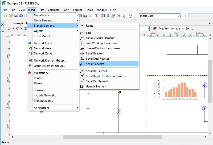
https://www.youtube.com/playlist?list=PLJExit9rQ0EqWE5FfR_IVVVBv6j50DckY
PSS® SINCAL Platform 19.5
Face-to-face / Online
Trainer: Dr. Saeed Roostaee (Profile)
Online Sections:
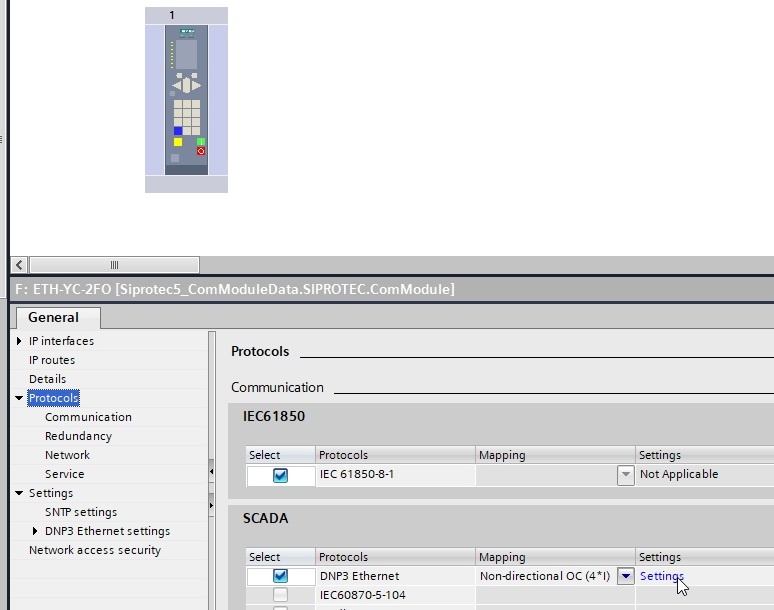
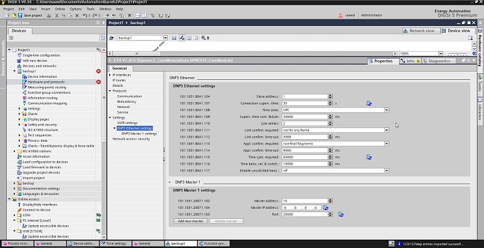
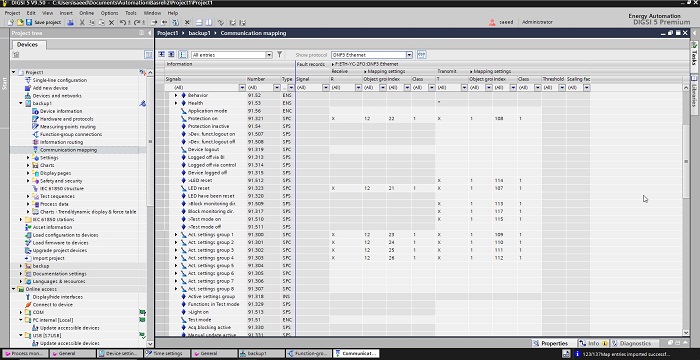
Configuration in DIGSI 5 SIPROTEC 5: basic DNP3 settings of TIM/CP (Device Configuration); configuration of a DNP3 connection in DIGSI 5; SIPROTEC 5 time synchronization in the DNP3 protocol; transferring analog values, counter values, and Boolean values time stamping, and event-buffering; Transferring Commands and Setpoint; peer-to-peer communication; serial & IP/Ethernet-based communication;
Exercise for simple system configurations with Ethernet-based networks …

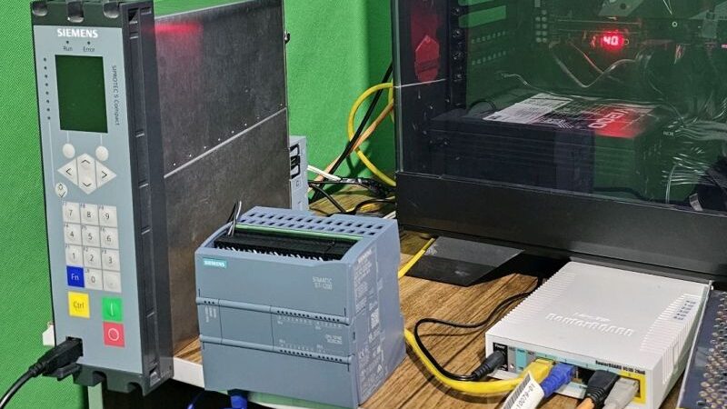
| Date | Status |
| 22-24 March 2024 | Full (no seats available) |
| 6-8 May 2024 | Open (EUR 1100) |
| 18-20 June 2024 | Full (no seats available) |
| 16-18 Aug 2024 | Open (EUR 1400) |
| 14-16 Nov 2024 | Open (EUR 1400) |

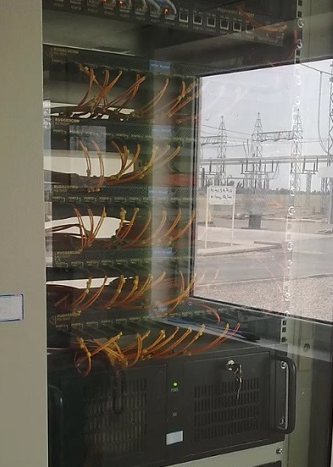
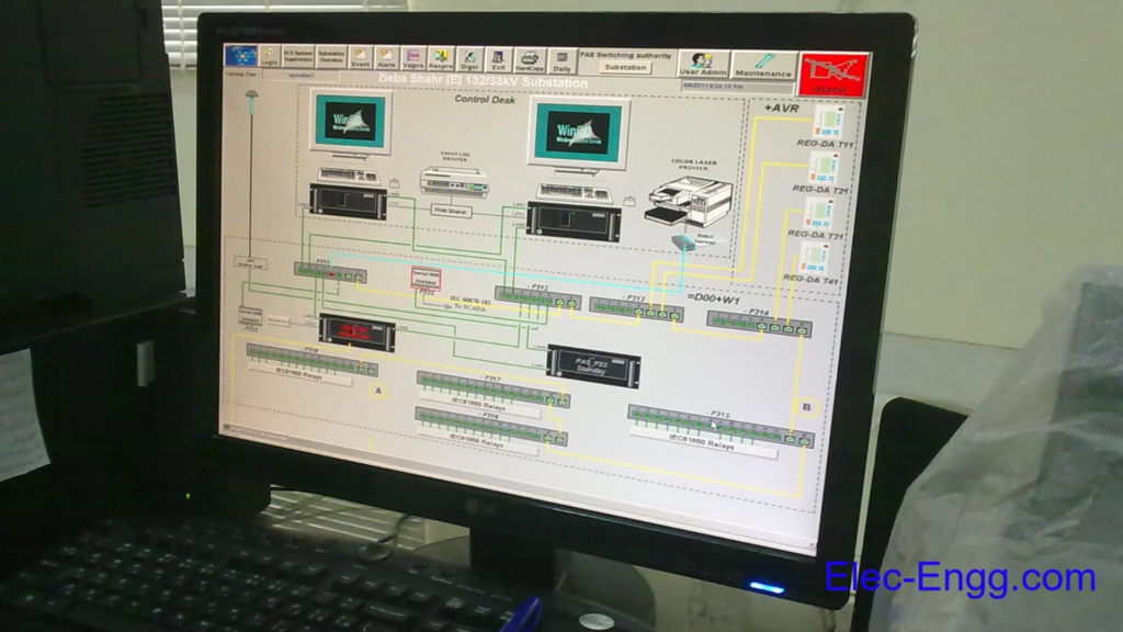
The Transformer Protection Training training course explains how the Differential protection algorithm works.

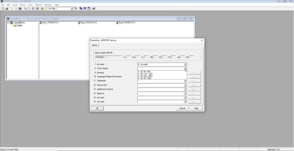
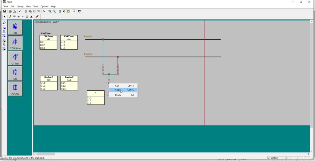

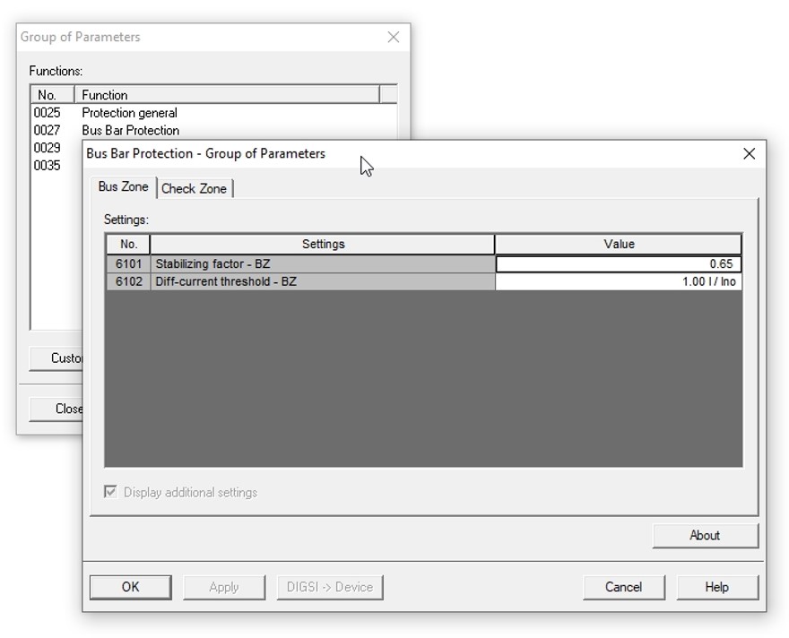
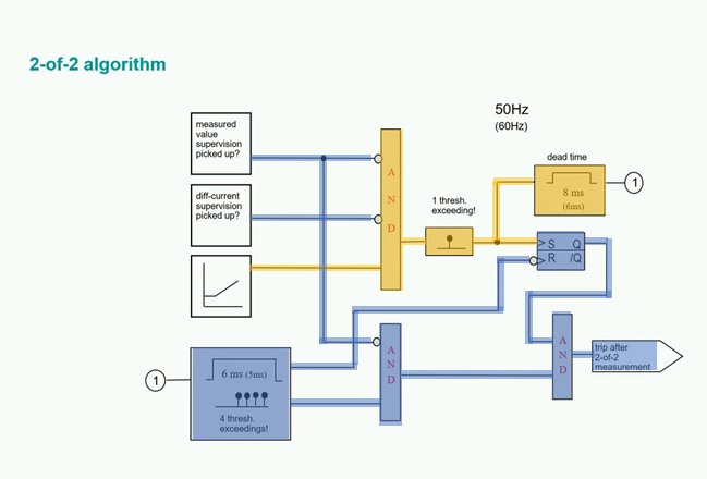
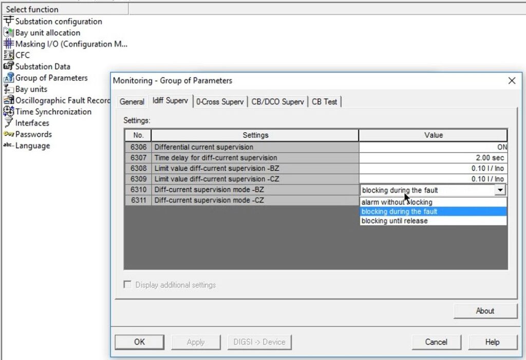
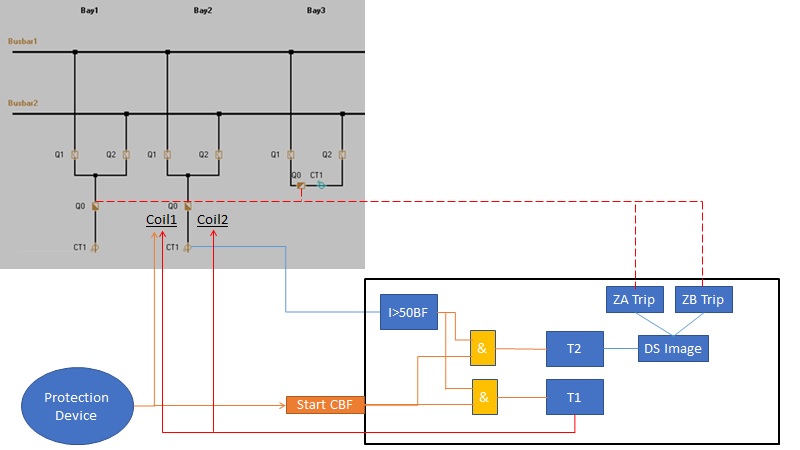
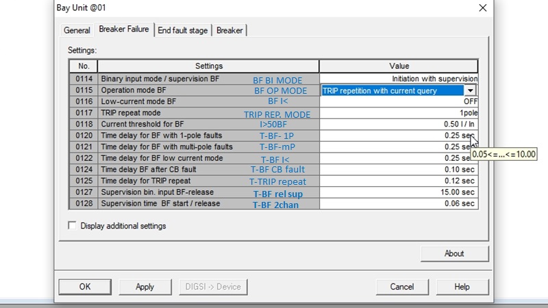
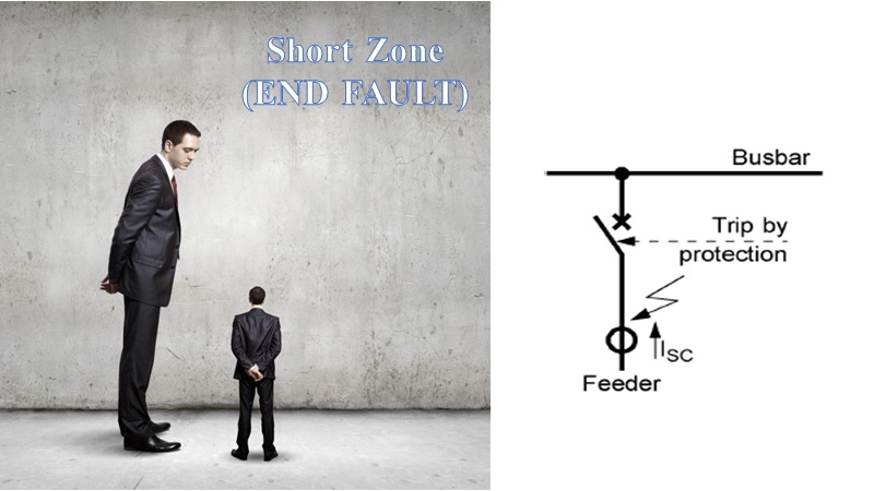
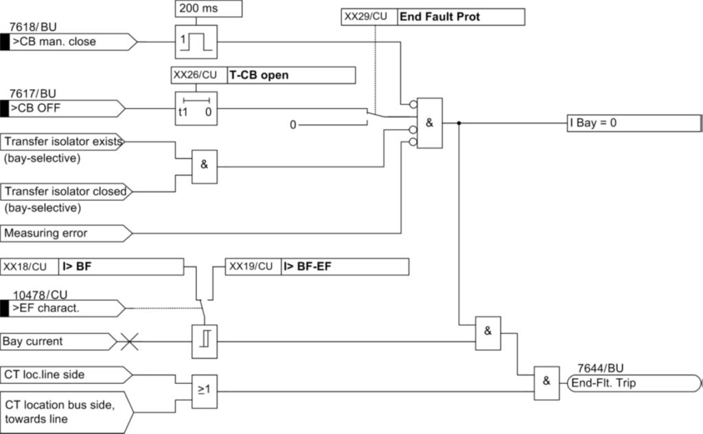

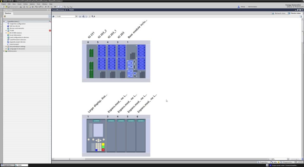
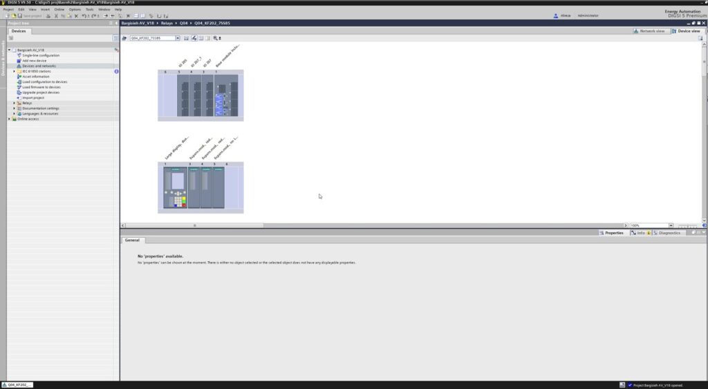
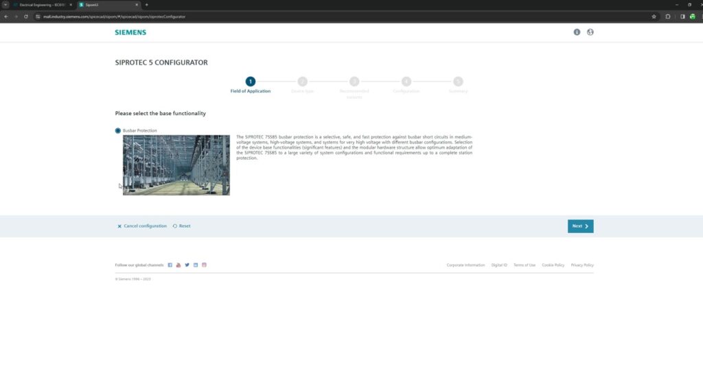
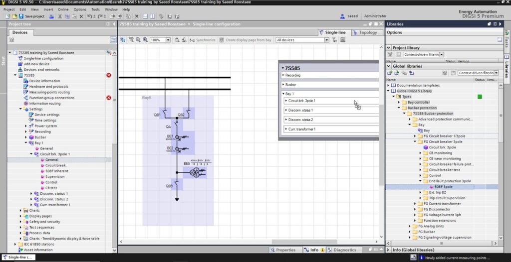
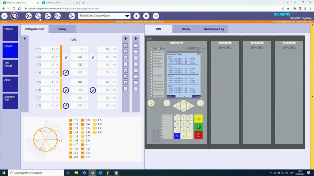
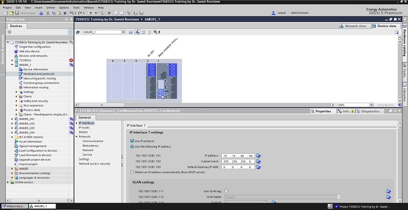

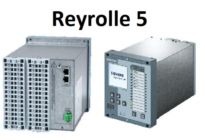

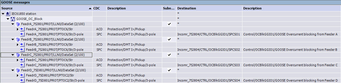
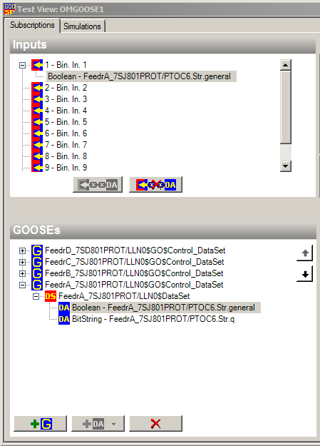


