you can start your learning from wherever you are.
You can save time and money.
you get a certificate of completion.
you can get free updates automatically.
Learning SIPROTEC 5 & DIGSI 5 with ease
Learning DIGSI 5 and SIPROTEC 5 relays becomes easier and more effective when the course is updated continuously and you can learn it anywhere. This course is pre-recorded, and all updates will be added for free.
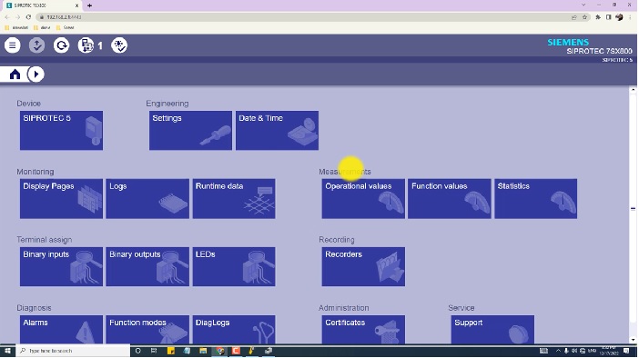
SIPROTEC 5 relay families and applications; How to install, transfer License and upgrade DIGSI 5; Import DIGSI 5, Device Drivers and Start with DIGSI 5 DIGSI 4 VS DIGSI 5 and DIGSI 5 Overview; Online and Offline SIPROTEC 5 Configurator; Functional Scope and Function Points; Working with Libraries and Elements; Managing Projects and Devices in Projects Single-Line Configuration; Signals; Information Routing; Routing Measuring Points; Function Charts (CFC); Display Page; Advantages and Disadvantages of SIPROTEC 5 and DIGSI 5; Case study project; Configure SIPROTEC 5 Devices based on diagrams.
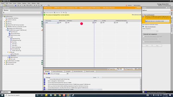
The spontaneous indication log which is available in online mode is a very good tool for testing and commissioning the SIPROTEC 5 devices. This log shows the indications immediately at the moment of occurrence (No wait for a cyclical update or initiating the manual update).
DIGSI 5 spontaneous indication
DIGSI 5 & SIPROTEC 5 topics:
Parameter set, Connection to an online device, Updating firmware, showing truncated texts completely, Showing tooltips, The Add new device entry is an action. This lets you open a dialog to add a new SIPROTEC 5 device./ Open the Device View to configure the hardware of a SIPROTEC 5 device. Adjusting Working Area, Maximizing the DIGSI 5 working area, Minimizing DIGSI 5 working-area objects, Splitting the working area vertically or horizontally in DIGSI 5, Separating objects from the DIGSI 5 working area, Restoring the working area, Starting to Add Using the Project Tree in DIGSI 5, Single-line and display elements in DIGSI 5, Global DIGSI 5 Library, Starting to Add Using the Single-Line Configuration and the Library, Select Voltage Variant, Select function point class, And port J functionality, Application Template, Communication firmware version, Network view, and device view, Plug-in modules, Siprotec 5 online configurator, Update short product code list /TNS list, For instance, line protection, SIPROTEC 5 7SA, SIPROTEC 5 7sa82, SIPROTEC 5 7sa86, SIPROTEC 5 7sa87, SIPROTEC 5 7SJ, SIPROTEC 5 7SD, SIPROTEC 5 7SL, SIPROTEC 5 7VK, Overcurrent protection, phases 50/51, Overcurrent protection, ground 50N/51N, Directional overcurrent protection 67, Negative sequence 46, Voltage-dependent overcurrent protection 51V, Directional overcurrent protection, ground 67N
To join our protection relay WhatsApp groups, please send “interest” on Whatsapp,Click
Discussions sample in groups:
– In Siprotec 4, the default password is 000000 – Hello friends. How to recover siemens relay 7sJ801 from monitor mode? – Just turn off DC supply and turn on. – Just In Monitor Mode, you can see the reset option in the drop-down list, please reset the relay and it will recover to the original. If It happened after the FW update, You have to initialize the device.
– plz tell me about PSB protection operated in brief. – PSB function avoid a huge load of fault. as a matter of fact metering, DZ/DT.Since a fault is high speed but a load is a low speed or DZ/DT – Performance monitoring reporting system In the MICOM Transformer relay manual it is mentioned that 41% of winding (Say 20% setting of In if CT secondary is 1 Amp) will be covered under differential protection and the balance 59% will be covered in REF protection for star winding connection transformer. My Query is how much winding will be covered in differential protection if transformer windings are delta connected Dd1. – Is there any document available to understand how the current flows inside each branch of delta winding during the health conditions, during Phase to Phase fault, and during Phase to Earth faults? – Please can you help out by briefly explaining, how the problem was resolved? – if it is Dd Connection then REF can not be applied unless you use a zigzag transformer as a grounding transformer. if so then you will use the same percentage – Hope License is the problem, please try with a Genuine License Number. but I did put a genuine key when asked during the DIGSI installation – Hope, License might be utilized before and it might not be multiple user License. Please check with Siemens.
– I’m getting an error while installing DIGSI 4.91 in Windows 8.1 saying the operating system is not supported – C&S make MRR1 rotor Earth fault relay is not giving any alarm when output is not connected but it’s giving alarm as soon as output wire is connected, What can be the cause – is it a dry contact? – Yes – maybe the internal relay is powered by the control voltage itself. does it happen in other relays also? – No What type of relay is this? Try to avoid this type of msgs – Output relay testing procedure is here in this manual
– Anyone experienced in MPD 600 for PD measurement – Hi, how pilot advance transformer (PAT) works? How its connections will be? These transformers are used in rural agricultural feeders to ensure 3 phase power during non-peak hours and single-phase supply during peak hours. (single-phase supply for rural houses and three-phase for agricultural motors in farms).
– Dear, someone Will have the IEC 60480 standard – https://www.sis.se/api/document/preview/566910/ – PSL in micom relay, areva ,Siemens, Abb, and SEL?! – Micom – And for other brands? – 1. Areva, Schneider, Alstom, GE – are using Micom products-PSL-Programmable scheme logic 2.Siemens-CFC- Continuous function chart 3. Abb-ACT- Application configuration tool -And SEL? – Psv – Please sir do you have a procedure on how to commission RPH3?
– could you share about the SOTF function in distance Relays? – Switch on to Fault – If ur going to energize one feeder in that feeder has a fault is existing and we gave a closing command to Breaker, then in that case SOTF protection will immediately trip the Breker.
To know more about our PSCAD Training click on the picture
– Please explain the time synch process in Simense relay using SNTP. – Anti-pump relay – Anti pumping to protect the closing coil
– Some switches come from the factory but you can also design logic. – Some power switches. – please anyone, how to read the ICD file for abb relay? – Go to parameter settings then click on the file from the menu bar after that select export parameters and select which type of file you want to export – Siemens 7sj8011, how can we change it? – Through DIGSI Software – Use DIGSI. Only by software DIGDI
– What is pre-close and post-close in trip circuit supervision, can anyone explain? – This is for the trip circuit supervisor relay concept. Pre-close before closing the breaker trip circuit in healthy condition. Post close means after closing the breaker trip circuit healthy condition. This trip circuit supervisor relay check the trip circuit coil must be healthy in pre-close & post-close conditions. If the trip circuit fails protection relay give any trip commend it will not operate. That is why the protection scheme has two number trip circuit schemes. This is called pre-close & post-close.
– Please I looking for ABB RED 615 file setting for comparison. – How to set Directional overcurrent protection? – Very nice, also when mechanical protection operates. it will send the trip command directly to lockout without going through the main relay. – Breaker is not working automatically. we need to press it manually for the operation of the pump.
– Breaker or contactor? – Contactor – we need the schematic diagram for the rectification – Quickly check the float switch by force, if the supply is not reaching up to the contactor coil, then there may be a problem in the loop or float switch itself.
– Download the S1 studio password hash generator – And set a password – AAAA – Please explain the function of the resistor connected series in tripping coil – It’s the trip circuit supervision circuit. It limits the current through the trip coil below the pickup value. – A diagram is not clear! – Can we use single pole ac MCB in DC Circuit in negative polarity where positive polarity is grounded, dc system voltage is -48V. If the answer is yes then why? – Brother MCB has nothing to do with voltage. In your specific circuit, whatever the voltage is, doesn’t affect MCB. Any kind of circuit breaker works on Current and it will work fine unless your circuit is designed ok. Even then it wouldn’t be a circuit breaker that would be an issue but the design of the circuit. – But I am asking about dc and ac MCB difference. Whether the can be used interchangeably -Yes they can, I have used them But it depends on the insensitivity of your circuit as well. if an MCB is designed for AC, it will trip sooner if used on DC, in case of fault. In normal conditions, it works fine – What I think is all breakers are rated to work with all types of voltages in ac and dc. – Only the short circuit capacity will change according to the voltage – Some are dedicated to DC, their coil doesn’t get heated as fast as AC. – Yes those are special breakers
To know more details about this package, click on the picture
– Where,s the protection system in these cases? – Hi. Is there anybody who has tested abb SwitchSync relay L183 Or any other SwitchSync relay from other manufactures like SIEMENS? – Synchro-check relay SPAU 140 C – but SPAU 140 C is a synchro check relay, not a sync switch relay – Switchsync PWC600 is ABB RPH3 ALSTOM. Controlled Switching with the Siemens Phase Synchronizing Device (PSD) the MCS025 Sync-Check Module Schneider
– Would you please give me test procedures or settings that have worked for testing these relays – GREETINGS FROM TRANSCEND HR CONSULTANCY! – Anyone has a good document to understand ABTS and TOP.
– Engine with a power of 250 kW 1500 rpm and a 1500 kW 1500 rpm engine – Anyone working or heard abt a company called Valmet? – Hi, There is an opening in Schneider Electric, Chennai, India for a Commissioning Engineer with 5 to 7 Years’ experience. Candidate must know on 1) Commissioning of Numerical protection relays ( Distance, Differential, Busbar, Overcurrent & E/f ) 2) Hands-on experience in configuration and testing different make protection relays with Omicron 356 / Double testing kits. 3) Provided setting calculations for the above-said protections including CT & VT sizing. Candidates may need to travel Global sites if required for commissioning and training customers.
– Could you share any data about the DCS systems in substations? – What kind of DCS do you want? – Siemens,Arefa ,Abb, Vatec, Wincc or sicampas -User: zivercom, Password: 0000, another password: Ziv
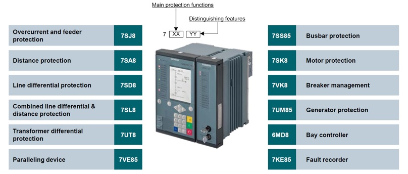
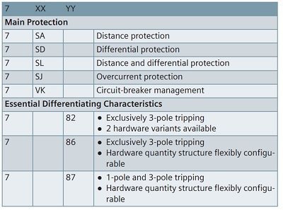
– What is the equivalent model of RED670 in SIEMENS? – 7SA52 – For Siemens relays 7SD…. means Line Differential Protection. 7SA Distance Protection as the main protection function. Depending on the device type distance or line diff is available as the main 2 functions. 7SL … Line and Distance Protection. (SIPROTEC 5)
– In Micom relays can I upload the revised PSL while the relay is in service? – Will there be any maloperation? – PSL uploading may result in Pick up of BI/BO and then output contact. – Check the connection Or disconnect the DC from the relay for a while and try again
– Has anyone done distance and differential relay calculation in excel? – Anybody has a calculation sheet in excel for voltage drop and current carrying capacity of cables Is it password-protected?
– Anybody knows how to protect the three-phase ground earth fault? For MV network. For single-phase, there are many ways but for a three-phase, we have a problem.
– I want to config distance relay model VAMP 259 but there is no option to enable fault locator. I can see the related option under the distance menu but nothing is submitted (in KM or Ohm), is there any way to enable fault locator? – Three-phase to the ground will not detect as earth fault because no zero sequence or no current will flow in the neutral. It is just an over-current.
– A 132 kV SF6 circuit breaker rated for 220 volts aux. Voltage is to be used in a substation where 110 volts DC voltage is available. Please advise which changes are necessary to be made to the Circuit breaker. – If you want to modify the equipment in the circuit breaker for 110v you need to change more equipment. Better try to connect the two 110v supplies in series – When the available voltage is 110VDC, Change the following parts 1-closing coil one unit 2-tripping coil two units 3-all the dc contact relay. Otherwise wise Manage 220VDC Indication Lamp
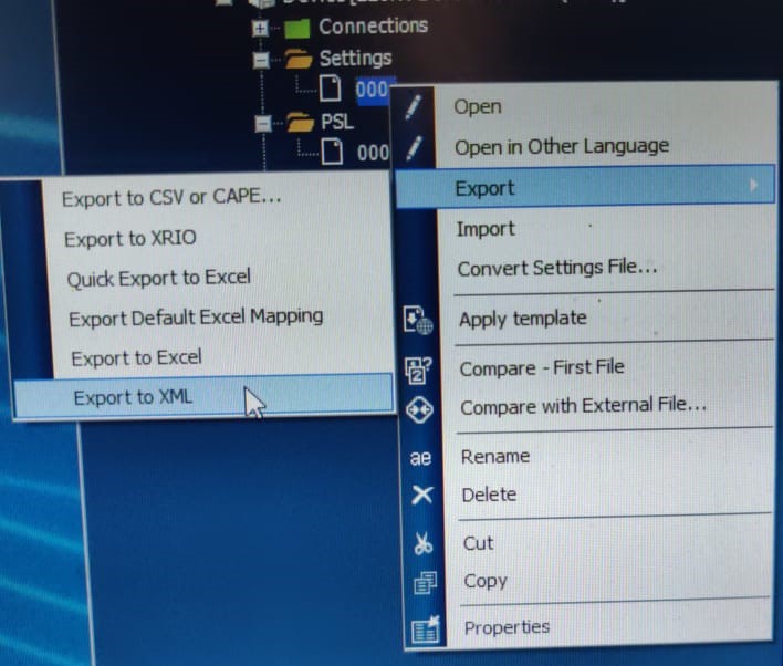
– I am trying to export Micom 442 set file into xrio format by using Schnider s1 studio, but IML cannot find xrio option in the export menu.
– You can go to setting file on the right side of software, and press right-click by mouse, and go to export setting, Rio – I did it this way, but xrio option was not available. I think the software version does not have this option. But I am not sure. – Anyone has a good document to understand ABTS and TOP. – Anyone has a Method of statement For Transformer stability and Generator stability?
– Can you give me transformer testing IEC standards? If the SF6 in HV CBs becomes very low. What is the standard action in this case? does the CB trip or does it must be locked out? If it is locked out does any breaker failure must be initiated? – Stage 1 alarm, stage 2 block. Block gas pressure <•5 Mpa. Block is no more operation, open or close. If fault then if it is line Tele protection will activate if trafo feeder or normal feeder BF will operate. – In 500 KV if stage 2 appears the breaker immediately trips! Is it correct or need discussion? – In our scheme at 500 kV level, if stage 2 appears the breaker immediately trips, in my opinion, CB lockout must take place rather than the trip! Am I right? – I have only experience up to 400 kv Siemens CB, second stage not trip from CB scheme. But PSB functions can make trips. I do not know PSD (Phase Synchronizing Device)
– We are getting Generator Rotor Earth Fault in Relay. How can we ensure that it is a false alarm – this is dangerous to trip the CB in case of stage 2 appears. it may not be able to quench the arc properly as sf6. pressure is low. so it’s advised to block tripping in case stage 2 operates. – If sf6 gas content is reduced breaker trip – Level 1 OTTER TAIL – Stage 2 trip must be a lockout, which means Breaker will trip and shouldn’t Close until SF6 Gas is refilled to the specified pressure.
– Lockout means one needs to reset the Lockout relay before closing Breaker. But don’t reset until the gas is refilled to the required pressure. Nominal pressure for 132kV is 5.6 bars absolute.
– Does Micom P741 and P742 need separate software for the PSL edition? – No, s1 studio can do it. – but if I want to edit a single-line map of the substation? – In this case, you must use topology editor for Mmicom – Do you have any applications for that? – IEC 60076 – If you want to go with diagnostic testing for transformer please refer to C37.152 22/abb, 23:02 – abb: Can any tell me about IEC standards for GIS, MV switchgear, transformer, protection schemes, and IED testing and commissioning
– NIC NO RESPONSE in Micom p142 and p143 What to do to solve this problem and what is the cause for it? Problem with the hardware. -restart the IED, the alarm will disappear and after some days alarm will come again. Permanent solution: Need to change the network interface card and update the respective nic file to that board. – Plz share Rio/PTL file for P44T relay Alstom make,
To join our protection relay WhatsApp group, please text us, Click
– anybody has a serial number for the Micom topology editor or can edit SDL for Micom p741? – In Micom S1 studio, while uploading PSL files to relay, we get three options, the First is Enhanced logic only, the second Logic only, third Full form. My question is what is the difference between these three options? – The difference is in the settings updated with the PSL update.
– In the below attachment, the Generator Stator earth fault is detected by connecting Neutral side NGT secondary voltage in series with Phase side open delta voltage which is derived through external IVT. The query is how this works and what will be the output voltage of this combination which is measured by the MICOMP345 relay. – Someone had omicron test templates cmc356, for overcurrents, differential, etc, and also some good bibliography for generator protection.
– Does anybody have a protection relay testing handbook – As you notice this book is volume 4 in the series. I would appreciate it if you send volumes 1-3
Here is one of the other video training courses, ABB PCM 600. You can see detail by clicking on the picture.
– I have a problem with the earth’s fault. We have used Siemens o/c relay which is functioning very well for o/c,e/f, and s/c. For the earth fault whenever it’s happened either one or two phases it’s working, but whenever it’s 3phase. the relay is not working. – Always trips with 3phase faults? – For another fault it’s ok but the 3 phase Earth fault is not detected by primary current injections each phase individually functioning. – What are the magnitudes and angles of the 3 phase currents you injected for the test? – What SIEMENS OC relay model? -7SJ601, Version 3 – The earth fault setting for stage one I> 15A. If faults are even 20A no functioning. 3 phase fault is not an earth fault. even if 3 phases to earth will not detect by earth fault protection. – If you inject three equal magnitudes with 0,120,-120. the earth’s fault will not function even if it is more than the earth’s fault setting. While you are injecting current, check relay measurements and make sure that the neutral current exceeds the setting value (15A). If the current exceeds the setting then you have to check whether the directional function is enabled or not. Also sometimes you need to check the earth fault calculation method if it’s measured or calculated. Finally check the current connection to the relay. Make sure that the current circuit loop is closed – balance values will not initiate the earth fault function. – I agree that the balance magnitude will not result in earth fault. Check the neutral current flow – The 3phase fault is considered a balance three-phase fault so no earth fault will detect, you need active o/c protection. Even if E/F operates with a three-phase fault it will be due to unbalance not a real earth fault. – Just reduce the setting for testing purposes and inject the current in all three phases monitor the neutral current flow now increase the current value in only one phase until the neutral current value reaches your setting value it will trip according to the curve. Check the setting whether it is nondirectional. – Hope you are testing the directional earth fault. Check the voltage magnitude which you are injecting into the relay.. it shouldn’t be zero. Most relays require a minimum of 3Volt for sensing the right direction suggest giving 10V in the Y and B phase and 5V in the R phase and injecting the fault current above the setting. – if the three currents are not shifted between them by 120 degrees, even if they have the same amplitude, it will trip because the vector sum of the three phases becomes different from zero. (Io # 0A)
– I am facing a problem with Siemens 7SJ8041 When Relay Trips on Under Voltage and Voltage comes back to normal and I try to reset the Relay Binary outputs and Leds then the relay does not reset. I have to go into the Test and diagnostic menu and have to reset the whole relay from there. any solution? – check the drop-out ratio of the relay. normal drop out is 1.2 for under-voltage.
– Secondly in 7s8041 Relay does not trip on Reverse Power – check additional functions available or not? -Yes available and setting at 166.5W. It is available in u/v settings. But you need a Laptop and active additional settings
– If anyone this relay manual English electric, CDG31FF8051JL(M), electromagnetic relay kindly reply me – If a transformer is protected with both REF (64REF) and Differential (87) as we know REF is more sensitive than 87 and operate for the unprotected winding near the neutral side. My question: is any 87 trip means also a REF trip at the same time? – No, REF only responds for earth faults inside the zone. if the fault is not related to the earth then the only differential will operate in the case of earth faults, both can trip the transformer( the faster will trip first), and if the transformer has high impedance grounding, the earth fault near the star point ( less than 40% of winding) may not initiate 87 ( when you apply slope and operation and restraint) in this case, only REF will operate. Right? – Yes, this is right. And this is why we use REF together with Diff protection.
– What is the difference between high impedance and low impedance when dealing with Differential and REF protections? – The high impedance method uses an impedance in series with the operating coil of the relay. The impedance value is chosen to damp the current of the relay under setting current in the case of the worst fault (a fault near cts with one ct saturated). The low impedance method uses a restraint coil to dampen the current of the operating coil in the case of the worst fault. The relay will trip when the operating coil current is maximum than the restraint coil current. – In which condition the operation of 52PD, pole discordance protection will be blocked? – the pole discrepancy is an arrangement of controls, typical of the power switch. – It is already blocked by time. if PD happens it must operate after 2.5 seconds.
– In which cases and configuration I must install and program “inter trip signal protection “in case of transformer protection?
– PD trip function is normally blocked by any pre-scheduled single-pole operation of CB like single pole auto reclosing or manual opening of a single pole of CB. – in the monopolar switch the discrepancy time must exceed the reclosing time.
– I have a 7sj62 Siemens relay and it’s going to monitor mode then I tried to initialize the Dex file not succeed and activated device reset from the HMI after that it’s gone again monitor mode and relay restarting automatically when power on – Hopefully by upgrading Firmware Version, it may work fine, kindly contact Siemens and ask for an updated firmware version. you must initialize the device with the digsi. – Please share experiences and knowledge about “power swing blocking” in distance protection – Hi guys, I need help setting up an auto recloser on the Sepam series 20 relays. In double bus bar protection, what is the difference between single CT and Double CT methods for bus coupler
🌟Follow the group rules and objectives of the group 🌟This is an international group, just text in English 🌟Actively participate in the group. 🌟Don’t make any personal message to the group members 🌟 Post your message in one single chunk of text, don’t post every word or sentence in a new message. 🌟Advertisements, announcement of the event of other groups needs approval from Admin before circulation 🌟If any member is not following the rules, we have the authority to remove them from the group 🌟 No greeting and another personal discussion. Do not say good morning, good night, thanks, etc.
– What is the use of Line CVT in relays? – Synchro Check
– How do you test relay GE SR3, Thermal Overload function with alarm and trip? – in DIGSI4 4.92, when I wanted to archive a file, this window was displayed and required a password And got this log file – There are some requirements for installing DIGSI like c++, have you installed them? – I need 12 units of the above to relay Fro where to get it?
– How distance protection is functioning in HVDC transmission? – Transposing is required in long-distance HV cables Or cross bonding is enough? – Both will be required – Conventional distance protection is not applicable in the HVDC system as the reactive part of the impedance is absent due to zero frequency – Cross bonding is required to reduce the induced voltage, and transposing is required to make C mutual equal between three phases. This job shall be done each 400 meters and cross bonding shall be connected with the earth by the special box or with SVL + earth – SVL mean shield voltage limiter
– When I tried to extract XML files from DIGSI, this error came. Kindly advise – It depends on how u extracted – There are 2 ways to extract – Which one was yours? – Both ways same error
How to tackle DC-link over Voltage faults In VFD. Application HVAC chilled pumps. G120
increase the DC overvoltage fault limit to 130%. default is 125%. but this solution may lead to stress VFD which may lead to some future issues.
Update ur firmware to the latest. It will work right away – old versions are not prone to motor oscillations which in case u free run a motor may oscillate. in which frequency band u r facing overvoltage? – Really I just retrieved data from the customer. But from where I can find it – siemens website. – No, frequency band – run the motor. increase speed slowly. you’ll start hearing sizzling sound in a particular band
– I cannot modify the protection setting on ABB REF 542 plus manually or online through cable. I always got “setting not saved properly”. Can anyone help?
– Hi. I used the key to change the protection mode to SET. Is this enough? Should it be used also to change a setting? – Please anyone can help me with the password viewer for ABB Red 615. We are facing one error while installing ABB PCM 60. Can anyone help? – Try to Separately download and install SQL server and then install PCM – anyone knows about this error while exporting in. XML extension? – This is the 1600A breaker feeding the Chillar. Could anyone please tell me what would be the setting of this Breaker for Long, Short, Inst. & Ground? DLL file is missing. Copy the DLL file from another working laptop(C drive) or reinstall the software. For long char. Settings are 1.0 and time is 3.0. Switch not clear but for L =1 and T=144s ;S=1.8;I=8;G=.4 – Can anybody tell whats the max current in which we can use MCCB only for load break? – Cable size 300sq mm – That’s due to thermal effects. The thermal tripping point would go down after each tripping and if tripping takes place at 370 A after 2 hours, the MCCB might trip at 350 or even below (may) after every one and a half hours or even earlier – Then what solutions shall we change this MCCB if yes what would be the rating. any other solution instead of MCCB because it’s placed in between transformer secondary side and LT panel. – Check the tightness of each bolt Properly torque it. – Phase sequence is ok my site is running fine load is 240 kw. 240 kW? rate amp is 408 amp. This is a connected load but running is 225 kW – Can you test the MCCB By primary injection? -383 amp – There is an overload, short circuit, instantaneous, and ground fault by doing the method of primary injection? – Yes I am doing by primary injection only – Can u tell me which combinations for overload test in primary injection? Single-phase or phase to phase? – You can use Phase to phase and phase to neutral for overload, instantaneous and short circuit. And phase to neutral for ground fault.
I can’t open the IEC61850 station in DIGSI 4.88 – Maybe the target digsi file version differs. – What should I do? – Install Digsi4.91 & try. – Anyone who has Digsi 4.88 update? – It use Siemens-Configurator-Version”>04.88.08.995 – Create Siemens User ID & u can download it on the Siemens webpage
– what is the maximum length for a line that can use Teleproection in distance relay? – Which relay? All relays have different limits – Siemens – 400km, 300km, 200km,100km, I talking about the distance I can use Teleproection in distance relay?
– Hi everybody, does ABB REL 511 have an under frequency and over frequency protection? – No – Is there any way to activate this feature in this relay?
– What is the default password for Easergy Studio 7.1.0? – In Easergy studio 8.0.0 the procedure to connect to relay is different, has anyone been able to use that? – AAAA – Thanks but it does not accept – Use the Micom studio hashtag for crack.
– How to calculate maximum through fault current to set the relay stable in bus bar protections? Say voltage is 400kV. – It was based upon your load – If exact load details are not available? – I don’t have a clear idea but have a suggestion u can decide regarding your CT primary, But the normal load current may be less than the CT rating – How to create CID & ICD files to ZIV 87T(CGL make) relay for integration with SAS? – You can get a rough idea of the maximum CTR of all the CTs connected to the bus.
– Please I need to communicate with argus 1 relay over current reyrolle by rs 485 – You can not extract. The only vendor that can give you – You can edit in ziver cid – Sir I don’t have CID, then how can I edit? – Arrange to take from the vendor. If you don’t have CID then get it from ziver CID soft. You can Extract the CID via ZiverCid software. It will create the file, And btw you should not be touching ZIV relay if you do not have a basic idea of Ziv software Because there are chances you will make the firmware corrupt For which you have to make it a hard reset, which is also not an easy process, short but risky. So please contact your senior on-site & inform him about the situation. Otherwise once the relay is gone into the dead mode, it won’t be even hard to reset by calendar method – I have ZiverCID software then how can I extract there is an option? – I think to go to ziver complus and then setting and then edit. This file will automatically open in ziver CID. If he has CID module installed
– Hi, Is anybody familiar with the F650 GErelay? – What do you want to know? – About Plc logic configuration – Can we write the logic for transformers changeover -How do you want to make it work as a changeover? – You must have that. Download use Filezilla to extract CID. For extract, you don’t need any credentials With the definition of CB status and timer. For download username: Ziv And password: *ziv#
– I have a problem with my fault recorder, 7ke85 siemens. The Disgi5 software show fault in port E, the front panel is active run (green), and error (red) Led. I can’t communicate – This fault locator is not functional As long as the error led is glowing. – what is the solution? – This problem has no solution -Yes in CFC, the ladder is having a signal which is not masked – Remove that – I can not inspect the relay, I can not communicate – Relay is in error mode means the software is having inconsistency between source & destination – If you have a backup check CFC and send it to the relay. And if you are new to siemens relay, better do as I say, right away – When I want to communicate with the relay for local or remote but in two situation does not allow any communication the relay – That’s because of an ERROR in the relay’s file. This relay requires Re-Flashing of firmware
To join our protection relay WhatsApp group to be a part of problem-solving, please send interest on Whatsapp (CLICK)
– hi, I was wondering if anyone could please tell me how to check the measurement of 2nd harmonic content in the 7UT85 Siprotec 5 device? – In RET 670 transformer differential relay. I want to check the diff and bias current I found Please solve my problem related to NR relay. -When AR has been operated in 400kv line then one end AR successful while other end line became trip while both ends have AR-enabled. then why? – On other end, it is operating in Pole discrepancy or AR lockout? -No. Direct trip -Check all conditions for AR in other ends – On other end, it is operated in Zone 1 or Zone 2? – Zone -1 – CB’s health status is ok? Yes – It means? – No PD and AR lockout operated trip command goes to the breaker – I suppose u assigned any DT to send a signal to the remote end? While AR From the local end – Check the time setting at both ends Of the AR – 86 Operated? – At one end it may be 1sec n other end 350ms – So by the time at one end AR operated it sent DT signal to other end – Then you check the logic for 86. 86 should not operate for zone 1 single-phase fault – Due to which 86 operated. DT received in the remote end? – Carrier received at other end And carrier send by our end? – No DT received and send by both end – Carrier aided tripping sent from your end – No this is not correct.86 operated for single-phase fault -Ok. On the remote end, 86 is operated or not? – Yes. Then check the logic for 86 in the remote end. I think in the remote end 86 is assigned for all faults. Check the time setting at both ends for AR. Both end Fault in Zone 1 then ZCOM Trip will not happen. That is not necessary.
– Anybody has 500MVA 400kV/220kV/33kV T&R Make Autotransformer 8 Channels FO-based Tempr Hotspot details Based on FBG?
– Please help, what type of fault it’s showing? This relay connected with 3 phase motor – STS light blinking. The motor run for a while and the stopped Resistors are rated in ohms and wattage. How to identify the short time withstanding wattage of resistor which is available in hand? Generally, how much will be the short time withstanding capacity of the resistor for rated capacity? Working in System Protection as Manager Power System Engineering. – We are providing all the testing and commissioning services in Electrical switch gears. – How did this one become a big day? – We have to think before using electricity. Go green. Think before use – What are FPFM and FPSM in Line protection relay? – FPFM. This is meaning feeder protection is the first main. FPSM This is meaning: Feeder protection second main – Set-1 and Set-2 right ? – Yes
– we need support for setting calculations for the transformer feeder which fed on 13.8 kv. – here in Saudi Arabia we used feeder protection (Line) 2 relays, both make the same function, have the same setting
– As per your requirement, he is having more contacts regarding purchase. – I want to synchronize my server with a Meinberg GPS in SICAM PAS .anybody can help me? – Which model of GPS are you using for time sync? – M300 – Yes I can not start NTP on my server – Why don’t u try SNTP? – What’s the networking protocol you are working on? – As far as I remember M300 is compatible with NTP & SNTP both – Firmware MUST be updated – NTP – What? NTP is NOT A NETWORKING PROTOCOL. – Oh, my network protocol is Ethernet
– Siemens Siprotec 7SS52 Busbar Bay Unit in error & alarm mode, after removing & Connecting Aux., DC supply, it will come in Run mode & after 30min again the BBU goes to error mode. What is the solution to this problem?
– Initialize main unit and bay unit from software or menu. – Reset MCU still having the same problem
-Hello need some help with this error Relay P643 Alstom make. Communication error – First, check the Test Connection and then proceed. In the test, the connection selects the correct port to which your serial cable is connected. – Port is verified but still, the error shows while communicating. – We had used 2-3 converters but the same error was observed. Then change the port and try once – Which converter you are using? – BAFO And another is a local make – Try with a different port once – This error comes only when you are sending right? – Yes – Select only settings and not psl then send. – Tried but not working. – Sir, the port changed but the same error occurred. – Try to use a different converter other than you have – We have 2 converters same error for both the converter – If it has ethernet on the backside of the relay you can use that also – Which software you are using? – Agile v1.3.1 – New relay or an old one? – New relay – Try with Easergy – Changed port advance settings. Solved now
– anyone informs that Schneider which software is available for checking the Goose (IEC-61850) Signal? – The password of protection relay type p143 has been modified? is there any way to restore the default password. – why when the change between some tabs in kvgc relay is blocked? – NIC Card faulty – Replace with a new one – Reason for this problem is IEC61850 Support configuration file is not available in the relay at the moment. -I want to start NTP on my server but the system shows an error. anybody can help me?
– Can anyone define “breaker abnormal alarm” in the signal list? – Cb abnormal can be given by spring not charges, or Sf6 pressure or TC not healthy – Make or gate & give final op as CB abnormal -+Local selector – Polo discrement – When programming Nondirectional overcurrent test in Omicron getting Out of range error. How do I correct it? – CT Secondary 5 Amps – I guess you write the wrong number to CT primary/secondary ratio at device settings. Check again pls. – Use CMC 356. I think 256+ will not deliver this much. – Check the max amps settings in test object details. – use the 3x25A setting. Parallel three current injectors with other 3. This would provide 25A per phase. your requirement is 12.88A that’s why it’s showing out of range. – Please check the connection setting and select the proper port number and baud rate by looking into the device manager -Everything is correct only Check test correction once or use another serial cable. Check earthing of the relay as well as your laptop charger. – Check the communication port configuration from the communication menu usually this error appears due to wrong port selection and configuration – Yes, you uploaded the wrong menu text file to the IED. To make it normal you need to send the right default menu text file via parallel port again or updating the same firmware will make the IED to go default settings and menu text. If you are planning for a firmware update make sure that IED is not in service.
– I’m getting this error while installing digsi4.93 – I had V4.92 loaded and it deleted it. I tried again without V4.92 loaded but got this same error. – Do we require to test, “inter trip” during end-to-end testing of line differential function Or only for distance? – Yes you have to check
Our DIGSI 5 Course is available. Click on the picture to know more info
– Hi all I want to implement Autorecloser in PSL and assign an output contact to it (for Micom Agile p443). Which output logic DDB signals, Should I use?
– Hi everyone can anyone help me with this issue? I am configuring IEC. Here is my settings relay subnet: 255.255.255.0 laptop IP:10.22.91.100. now if I put relay IPs from 10.22.91.1 to 10.22.91.92, I get the response from it. but 10.22.91.93 to 10.22.91.253 aren’t working. what could be the solution? there is no subnetting, why is it restricting me to 92 devices? – Relay subnet and switch subnet must be the same. What’s the subnet in the switch? – does a switch has masking? I don’t think so. – Every switch has IP & Mask If you know the IP address of the switch – Type in ur browser, and there u can also check the subnet mask – Which switch u r using? – that is something diff, that is just to access the switch conf – the ports aren’t assigned to any VLANs – so no need for that – It is linked with relays communication, the relay fiber would be connected to switch if both are not synced, communication with IEC won’t work – You can check that as a part of troubleshooting – it’s working with IPs 1-92. That’s what I’m saying, maybe another switch has a different subnet due to which relay won’t be accessible with laptop IP – Install device model.
To join our protection relay WhatsApp groups to be a part of problem-solving, please send interest on WhatsApp (CLICK)
– I have faced some issues in Micom p642 agile regarding fault recording trigger. Relay doesn’t trigger at the time of differantial trips so please help me with it I have tried all the options for the fault trigger all other faults are triggered but when only differantial protection trip at that time fault is not triggered or on the graph was generated.
– Micom relays and SEL RTAC connected in the same network.. is it possible via RTAC, DR files from Micom relays can be downloaded – future scope of power system protection. future scope of relay coordination. What innovation is required in relay coordination?
– anybody having a protection relay panel O&M manual of any Kv level. Pls, share if U have. – Please don’t touch any electric pole especially when it’s raining. – Any anyone knows how to test Thermal protection in ABB REM 543
– How to change CT Ratio in a secure Energy Meter? Could you share the P441 manual for the Areva brand? – I need software for Micom p 741. Remote HMI. Please
– When DC Source 1 is failed our Breakers got tripped. What could be the reason for the same? – Check CTD – Please share the control diagram of the breaker with us. Selective tripping? – Undervoltage shunt – Kindly how I test REF in 7UT612 siemens with 1 phase current inject? – This wire is for voltage equalizing. so CT body will be the same voltage as a bus bar. if not connected will cause floating voltage for the CT body and result in partial discharging. – I think it’s a capacitive leakage wire to connect to the capacitive indicator. You can eliminate capacitive insulators if your CTs have this capability(capacitive leakage).
– anybody has a VFD Test format or procedure? – anybody configures RSTP at Micom p546? – Guys anybody have a Test format for Diesel Generator? – Can anyone tell what could be the reason for the battery blast in dg during Cranking? – Short circuit on crank cable or in the crank. The second reason crank can be stuck or engine
– How to calculate stall rotor time in SIMOCODE? – Use VRLA type to avoid the blast – This battery is 12V;180AH Tata make almost 2.5 years old used to crank 415KVA Dg – Is there any pole calibration happening in ACB for any make to close all-pole at the same time? And if happen then how it’s done? – Why do we use a coreopsis conductor inside a tubular conductor? – If anyone facing this issue in Siprotec 5 BCU(6md86), after restarting the device then manually operate the master trip relay (86.1&86.2), that same time given reset command from SCADA but it’s not getting reset. while communicating ABB relays, how do I know which versions of PCM I need to use? ( 2.6 or 2.9)
To join our protection relay WhatsApp groups to be a part of problem-solving, please send interest on WhatsApp, Click
– What might happen to this insulator failure? – Sepam 80 fails to operate shows maintenance key 1. any ideas? – Converter issue – Which converter? Relay is communicating on Ethernet/LAN – In VT secondary injection. How to calculate phase to phase voltage in unbalanced conditions? Eg. we inject 20V in the R phase & 40V in the Y phase. What should be the phase-phase voltage? In actual condition, the multimeter reads 53V. how to prove it theoretically. – vector sum – Ip1(cosPhy+i sinPhy) + Ip2(cosPhy+ i sinPhy) – Values are not matching.
– how to calculate the operating region of directional overcurrent and earth fault relay? – u cant add a real and imaginary part. I= 2root ( real sq + imag sq).this is how u add a real and imaginary part – Can anyone please help me provide an XRIO converter for RED670 V2.1.0? I’ll be grateful – Can anyone tell me the meaning of the number mentioned in the box? – Order information I believe
– I need RDS-pp codes for equipment used in the wind Power plant. RDS-pp is a Reference Designation system for power plants. – Digital kits like omicron, meggar can inject voltages and currents of desired magnitudes. – As a Protection Engineer you have to roam all around India for different projects. – I am getting a network error while downloading from the server
– Anyone can explain CT sparking – Looseness or open Circuit – Isolate the system to avoid any mishap – Loose connection on side phases!
– What is the main difference between low impedance and high impedance bus bar protection schemes? – High impedance in the Low impedance relay is nothing but based differential relay in this we have the slopes to avoid relay operation from the through fault current and CT saturation condition also.
– Hey I need help can I find here someone who works with Elster A1800 consumption counting – Anyone has auto manual change over test Format. – CT connection is ok? – check the serial cable. also, try (test connection) from the device list. -Tried with other serial cable Problem solved.
– what is the criteria for Grounding control and power cables, should it be grounded from both ends or one end” And the reason for grounding is both sides or a single side? -1 core power cable shield must be grounded only from one side, otherwise transformation current with inducted to the shield. I&C& signal cables as well. In this case, the induction is from the outside. However, for 3core, 3phase cable it could be grounded in both sides – what about multicore control cable? – In Siemens design which is used for many power plants, it is mentioned that only one Side must be grounded to prevent circulating current.
– Hi world someone can help me with F650 HMI with GE config. I need to make hmi with Modbus protocol – Check relay HMI -Should not b in the Submenu? – Make it to the main menu page -Plz check the Technical key of the IED in the software, is that compatible? – Check the report details in the common read/write tool to get more information. Note: It’s not recommended to do a common read with a lower version of PCM600 if the IED is configured with a higher version of PCM600.
– display error name is flashed v1.0, – For parallel operation, you need to synch both transformers first, then close the breaker. Changing load from one transformer to another, Different tap positions mean different voltage levels (if both transformers are fed from the same source & in case of under-voltage, the load will draw more current, which might result in OC Fault, overheating of cables. The breaker may trip in the second case but in the first case, straight damage if you haven’t installed AVR. Breaker doesn’t care for Voltage, it only trips on high currents, But one transformer connected to load which has a voltage of 10.4KV – it mainly depends on uk% and loads current. having enough data, you can simulate the Network using DigSILENT. In my experience, you can parallel both transformers without worrying. – Check impedance voltage percentage Within limit, u can – Check impedance voltage percentage at nameplate data -When u have two transformers in parallel then you may have to look at the circulating currents that might flow when tap positions are not matching. Account for that circulation current as it will be an issue – Sir the same I read in a document due to low impedance in the transformer which has less tap position certain amount of current will circulate within the winding but why? – difference in impedance of the transformer more than 10% will have a circulating current too. even if taps are the same and the voltages are the same – 66kv breaker CG make -There is no need for SC capacity coordination, your new breaker may be oversize but that’s not a problem – 40kA/3sec means it can withstand up to 40kA which is higher than 31.5kA. if 31.5kA for your substation is ok, then 40kA is ok, too. – Not a problem higher capacity only.
– Can anyone have an idea, what is meant by the cross trigger input TFR (fault recorder)? – Cross triggering is used between TFRs to initiate recording all the TFRs and provides system-wide dynamic recording e.g. Power swing
– Please provide earthing in HT cable termination at both ends, must in HT earthing is very important – In transformer slope testing what is I bias calculation that needs to be set in the omicron test? – What is the IBias calculation equation to feed in the omicron differential characteristics for generator protection – When we send the configuration to the relay we will face a syntax error at the last step, what is the matter? – Depends on what relay u are testing. – In the shot test, you choose the points on the characteristic curve and the software tests only at those points. In the search test, u select the sweep for IBias e.g. 0.2 to 5 with some intervals. This will create vertical lines on the characteristic curve and the test set will then determine the Idiff value on each of those lines. The test set will determine the Idiff value at which the relay operates. Search is like making the test set determine whats the characteristic curve and if the searched point is within the tolerance limit then only the test is considered passed
– I have a p443 distance relay(Micom Schnieder make), I tested this relay in zone 1, but it also trips in zone 2 and zone 3 simultaneously..and although I marshaled output contacts to trip.. it does not send tripping order to test set. anybody solves this issue – Which test set are u using? Have u checked the current or voltage connections? Normally this happens when u are injecting current or voltage in reverse, which means the relay is looking in reverse. Check whether the reverse zone is enabled or not. – omicron 356 – U using a distance module? Check your trip contact type, And double-check the PSL file. – I test this relay manually through the test set, not through the laptop. I am using the time module. -Ok. First, confirm ur output relays are properly working and connections are ok or not. Force them from the Commissioning menu and check continuity using a multimeter. Check ur wiring. U using a dry connection or wet contact.? – Maybe the relay SOTF function is on – Good point. Ensure there is a pre-fault. time set on the test set. Normally it is 1 sec. – There are 2 issues. One is ur relay tripping on all zones. And second ur binary output feedback not reaching the test set. Solve them one by one. – Usually, zone 1 is inside zone 2 and zone 3 (if all your zones are forward direction).
– We have one 13.8KV (15KV sys voltage) Switchgear. Due to an increase in the connected load, we want to change the CT in one of its Cubicles. The new CT suggested by the Supplier has the following Specs: *CT 300/5, Burden 15VA, 5P10, BIL 10KV. now my question is the 5P10 & the burden suggested by them is correct for this MV Switchgear? I’ve seen some CT having 5P20. Where we will select 5P10 & 5P20? Also, do we need to replace the metering core, as well as a load, that is increased? – all CT replacements should have a CT CALCULATION ( sizing) according to circuit parameters. You should ask for this document first – To say if it matches or not you need to know the maximum short circuit current, and also you need to know your relay and cables burden because 5P10 means this CT will be stable and will not saturate in the range up to 10 times the nominal current and with 15 VA burden. If you calculate your actual burden then 5P10 might be equivalent to 5P20.
– if we have 1K ohm shunt resistors of 180W for high impedance cable diff port. But need to change the resistors to 500 ohms as per settings, so how we can calculate watts for 500 ohms resist I think the definition of the armature is not exact and correct – I was just skimming over the pdf and noticed that. The armature is where voltage is induced in it
– Do we have any stationary armature in the power plant machine? I haven’t seen – Alternator I guess? – In synchronous generators Armature is stationary and the dc voltage is applied to the winding on the rotor to have a rotating magnetic field – It is easier to have a stationary three-phase output than having a rotating one – Probably it is a technical dictionary For practical uses But from an academic point of view, things are different And brushless synchronous generators have a rotating armature. The rotating armature is mounted on the rotor to excite the generator’s field circuit – I don’t say that we don’t have a rotating armature. I’m saying that the armature and the rotor are 2 different subjects – I think there are only two terms of stator and rotor. depending on various conditions and requirements we use either stator as armature or field or vice versa. – Maybe in a special type of machine the armature is mounted on the stator And a field circuit is on the rotor. – And for the other type The reverse may be true – yes. if there is a time-varying magnetic field and a stationary coil. the voltage will be induced in the stationary coil irrespective of stator or rotor or field or armature terminologies may differ as per circumstances. – I think it’s not a network fault like a short circuit. It’s about the relay hardware itself As the title suggests Hw error – But that’s what I think I’m not sure
– How error relay has a hardware problem? – I can’t open the diagram. It’s a network topology for DMMs and Relays single ring with redundancy characteristics for the 61850 networks, but the question is the connection between HSR &RSTP is correct or not? And can I use PT-G503 or other switches required? – I think u can’t use different protocols in a single ring. But if u have a separate ring connected separately with the switch, there won’t be an issue. RSTP and HSR can both will work fine about the switch PT503, if it’s an industrial switch, it will work fine.
– Can anyone share the Easergy studio software password? – AAAA – Can anybody help me? This switch has been faulty and I don’t know why. – If you’re having a dual DC source then check the healthiness of both DC supplies. In some cases, If one DC source fails then the switch will give that indication – you should connect to the switch and read the logs. there may be an alarm for acknowledging for example a link was down, a link was disconnected, etc.
– Hello everyone, Need some help with testing of SR 489 Multilin Phase Differential Characteristic curve using Omicron Diff Operating Characteristic. Has anyone ever verified its operating characteristic? – In the one substation we have license errors in WinCC frequently (siemens automation)What I should do for getting rid of this alarm? – It’s a hardware key. U contact Siemens helpline. No, It,s software licenses cc no pas, We have a dongle for sicam pas And our server doesn’t have any problem – Error about pas cc configuration – I think I have missed this license – It is showing In license.log what is exactly missed – Ok I will check it – This license is trial and limited – If you press the details it shows what is exactly missed – Ok. How I can repair it? – https://support.industry.siemens.com/cs/document/24200966/ – But one question, what about the WinCC License? – I’m dealing with SCC 9, for using that version we have to install WinCC at the first step, license it, then install SCC and license it – Click details.
-PASCC-configuration license is missing or expired – but how fix it? – The trial version is expired. This is for deleting the trial version
-I need to know just how to communicate with the relay and uploading and downloading procedure? – I tried to communicate TIA15 – Regarding communication and upload and download I need to know the actual way, Because I have experience in Digsi and reydisp software with that I do that blindly but I couldn’t get the correct methods
To join our protection relay WhatsApp groups to be a part of problem-solving, CLICK
– I Install PCM 600 software, after the installation, I update the connectivity package by using the update manager. It shows an error like that ” server couldn’t connect”. How to resolve it? – Check your connection, if you are using a private network such as your company this may occur – but I use my internet and I turn off my firewall also but it again shows the same error. – PCM needs SQLSERVER, this software comes with a PCM package and during installation, you will see that at first SQLSERVER is installing. Maybe it doesn’t install correctly depending on your windows configuration – It’s true but I don’t think is this problem, it’s most likely of being something with an internet connection, try using VPN – Uninstalled SQL server then reinstall issue will be resolved – In the one substations sometimes we have a false alarm. Can anybody help me for finding the reason? – Check IED events and the MMS 61850 mapping – Probably another event is triggering the wrong MMS mapping – the IED did not save anything in the events. How I can check 61850 MMS mapping? – Can you cause this event again? – You can use a package monitoring software – I should trigger this signal manually – I’m not good at supervisory but I’m pretty sure you can track down on this one the logical device/logical nod..etc until discovering which event is causing this false alarm – Please try to load the CID once again in the IED – It seems they are some kind of GI? Don’t you think? Anyone knows how to resolve – Restart relay. – Already restarted – Try to read with PCM 2.6 And PCM 2.9. Try with a different laptop. – Already tried with another laptop – Kindly install the latest Hotfix file on your laptop.
– I doubt if we install fuse and MCB in the same rating, then if overload comes what operates first either fuse blown first or mcb operate first if it is so why? Reason. The same for short circuit condition – Fuse – Response time is faster than McBride -Could you please share with me the response time for MCB and fuse? – The answer depends on the thermal capability curve of each – How we can clarify? Any documents for this
– When Three generators are running in parallel, suddenly one generator got trip. What happens to other generators? I know that the speed of other generators will increase but I don’t know why? – According to the drop curve In other words they all agreed to provide the grid with a 50/60 Hz sinusoidal voltage waveform. You can only see the actual increase in speed when you disconnect the generator from the grid. This question is quite complex, the generators are running on the grid or isolated from the Power system? If are connected you need to know how big is the influence of these generators in the system. In other words, you will need a load flow simulation and a transitory simulation engine to know what will happen with the other machines because synchronous generators have angular stability that depends on the intrinsic constructive characteristics. If the system is isolated is most likely that the tripped machine will accelerate and the other machines will decrease speed, if the variant of power is the inside capability and angle stability the speed regulator and the voltage regulator will set a new operation point to guarantee the operation delivering the same amount of power (sorry for bad English, just woke up) – Actually, this is on a machine connected to an “infinite power” bus. If we are talking about a big loss of generation the machines will swing around the main frequency raising/decreasing speed, right? – If the frequency of the other two generators was raised means the speed has to increase right? – Because for speed=120f/p In synchronous machines speed -> frequency. But again, it’s most likely that the speed of the two remaining generators will decrease. Once you have the same amount of load and have to decrease your generation the electrical current on the remaining generators are higher, this will result in a bigger magnetic flux that will make a force in the opposite direction of the primary machine (turbine), in other words, this should break the generator. But as our colleague said, in a big power system you shouldn’t have speed variations. It will all depend on your system. Is impossible to give a precise answer without the information? – The speed will decrease most likely depending upon the governor’s response if they running in an isolated system. A change in active power demand or production causes a fluctuation of the speed (frequency). If a generator trips, the frequency will decline. If the loss of generation is greater than the spinning reserve, the frequency could eventually stabilize at a new value lower than the desired one. However, in practice, under-frequency relaying is used to reestablish the balance between power demand and available production. If the frequency decline is excessive, generating units can be automatically tripped off causing an additional decline of frequency, and possible collapse of the system. Acceleration torque (Ta) = T (mech) – T (elec). For small variations 😛 (mech) ≈ T (mech) P (elec) ≈ T (elec)
– how to download Micom Alstom relay software If you have any software links send – Google MiCOM S1 Agile
– Does anyone have Torkel win 3.0 (or any) software available? – I need to download digisi 4.91 or 4.93 with Windows 10 Pro 64 bit – Anyone can help me to give me site, I can download it directly
– this relay does not turn on why? – Pls ensure the polarity of the Auxilary supply 26- Ok C1 is + and C2 is – – Are you sure about the exact output of your dc source? – Insulation failure at the termination… may be due to too much dust or deterioration of the Elbow connector
– Do you know how to reset the password of this device? – Yes, I have confirmed a polarity, some problem, relay not turn ON! – Is it a new relay? – Yes I used a CMC 256, auxiliary source. – When u turn On the supply measure the applied voltages on the terminals of the relay using a multimeter. – What happens when u use a test set. When u apply the voltage on the relay, the voltages drop. I face the same issue on Sr 489 relay using a CMC 356 – Check the applied voltage using a multimeter. – With changing the configuration and sending it to the relay, this error appeared, what the reason is? – Relay is in pickup condition, which function? – How can I find it? – Check General Introgation – Exit the pickup condition
– I am unable to connect through DIGSI – Can somebody guide me – Any fault is there – What is that LED glowing? – Check com number of laptop in device manager—> ports – Change your laptop serial Port configuration, Select the same com number in the laptop, and digsi. Maybe you don’t install the device driver. – Please check the VD address in ur digsi. Check your Siprotecs drivers
– Can anyone tell what is the password for the ABB 545 Feeder management relay? – To access the protection setting and to change the settings – Can anyone guide about Generator Overcurrent with Voltage Restraint protection – in our dcs system we can get disturbance records of all relays but one. I checked the relay with ied explorer, cfg exists in the relay but the bus doesn’t get it. The Comtrade directory address and everything are fine. Can I use Wireshark to see what’s happening to the file? I used the MMS filter, but I need a more specific one. Does the file transfer through MMS protocol at all? Can anyone guide me?
– We have AVR fed by PMG, can we disable the Voltage Restraint or Voltage Controlled function? – Kindly use Wireshark and check this shall help u – With which filter? – Can anyone in the group help with this – What is the effect of ambient temperature on SF6 gas pressure! – Guage readings could be different in day and night timings? Especially in winters – Pressure will reduce in Winters And especially at night, u might face an alarm or trip in the night and that alarm may go away in the morning – 7 bar at 20 degree
– During one phase PT failure, will overflux relay work? Has anyone seen this kind of voltage transformer connection? – Why is B-phase winding grounded on the secondary side? – Can u share the nameplate details of the PT. – yes, in an oil company, usually they only use 2 PT inputs and make it a delta connection in the relay – That’s an open delta voltage transformer or potential transformer. – It’s mainly used as an input to detect earth faults using neutral voltage displacement. – Typically the sum of the voltage across D7 and D9 is zero. however, should there be an earth fault and one of the phases hit the ground? you will get voltage across the open point. – Such schemes are used in ungrounded systems or on generator-transformer sets. there is no path for earth fault. – Sorry open wye but the scheme is the same. – Open delta connection, Yellow phase normally will ground. But as per the drawing seen some conflict. Normally 2 VT Winding we can see.
– This is a star connection with the y phase grounded Not an open delta. I was reading on the internet it’s some old practice followed in the UK.
– Anyone has any experience with diesel Genset paralleling on the common neutral resistor? How many generators can work connected to the resistor and how many can work isolated in parallel mode? That’s a very big open question. – Yes, it is problematic to solve its protection system. – Yes we typically run the neutrals to a common neutral bar. Install at least 3 the neutral earthing resistors and contactors – Are you talking about medium-voltage generators? – Yeah. – How did you calculate the size of resistors? – Please, can you share some calculations? – I need a setting guide for directional protection. – If any example for Double feed SubStation with the tiebreaker normally closed – What is the Apts scheme?
– For this system, with the two Transformers secondary breakers and the tiebreaker normally closed, and installing directional on the two secondaries, I need some guidance on how to make the setting for the directional, And if anyone has a similar case I will be glad if he shares his settings and how to make them? – the intention of the Directional on the secondary side is for backup protection? I ever encounter an application that uses the secondary side 67 as a backup by looking up into the transformer and if it operates it will trip both HV and LV.
– Can anybody share about the zig-zag transformer? Principle operation of it.
– Anyone has SR 469, SR 650, and SR 750 test formats? Which is software used for these relays? Anyone pls help?
– What could be the cause of the SF alarm? – PLC is communicating with another PLC over Profibus – Well, it can be a lot of stuff, but the first thing I always have for this alarm. SISTEM FAULT means that you may have some unit programmed inside your PLC that is not connected in the field. – So if it still works let it be – with that alarm all parameters of the slave address become red – This is not something to concern, just be sure you have a good backup of the PLC program. but if it remains, it will not let the startup of the Engine – Yes, but if it is already working, maybe is only a module programmed in the PLC but not connected in the field, but I say, I saw processes going on for Years with this SF, and nothing ever happened.
– We have a problem with the Generator Micom P343 that does not boot, please help us how to fix it, thanks – Check the ribbon resistance of HMI to relay. We have faced the same and asked Alstom then after they checked and replaced the ribbon, and fixed the issue. – Where is the ribbon? – Open the front side of the relay then there is a connecting ribbon cable u can find – This, is not Bad contact Ribbon the message is clear (Micom Booting) with Led Alarm lightning in red Fast It’s like PC booting, I think it’s a microprocessor issue. – We have faced the same problem in our reliance industries Jamnagar plant and Alstom itself give us a solution and change all the ribbons. Micom rebooting issue may be from the HMI problem/relay power card problem but if it comes even after replacing HMI look forward with manufacturers. It’s not just like pc booting issues. There is no chance of error in the relay or bugs like a microprocessor. – I might be wrong but I share what I experienced with the same problem. – Any vacancy for a Facilities Manager – How do I determine distance characteristics in the L90 GE relay? do someone has a commissioning manual for L90 relays?
– I want to know what you guys as an Electrical Department are doing to fight COVID-19 in their workplace. – 132kv circuit tripped showing R Y B phase and zone 1. And the same circuit is energized from another end at no load. Also, no fault was found on the circuit during patrolling. What will be the fault? Distance Relay type Micom P 441. It could be transient or pic up fault – Does it show any distance in zone 1? – Grid staff is not too efficient to check the fault recorder. I will go to check it tomorrow and will discuss it again – What is the status now does the line charge from both ends? – Only from another end at no load – Sir but usually these transients will be blocked by numerical relays rights – I think it may be DC grounding – Check the fault recorded to see the fault current and voltage – Lighting – Depending on the magnitude and relay Makes. We have had similar invent without any trace of a physical cause -can you share with us the Comtrade file
– What is the standard setting of the characteristic angle for directional overcurrent phase and ground (67/67N)? – does somebody has this relay technical manual ABB PCD for the recloser?
– Hi anyone has a static VAR compensator (SVC) protection scheme that can share? – What is the standard setting of the characteristic angle for directional overcurrent phase and ground (67/67N)? – For typical distribution networks (up to 33 kV), I set it to 30 degrees. For sub-transmission/transmission, I set it to 45 degrees, between the current phase and voltage polarizing quantity. – However different scenarios may require different angles and have to be worked out. – This angle for directional phase overcurrent? What about the angle for directional ground over_\]\]\]]]\\]]\current 67N? – Are there any references for how to make the setting for directional phase and ground overcurrent 67/67N? – I would typically read the relay manual, And use the default recommended value. The actual math behind setting them can be very tricky. – Which relay are you using? – Sepam s40 – The application is two parallel Transformers – What’s the voltage level and how far is the relay from the supply transformer? – From experience, RCA is 20~40 – For 67N, the value is dependent on the type of grounding. Please refer to NPAG, it was clearly explained there – Anyone has a digsi4 Activation Key? And for 67, if I am not mistaken, RCA is set based on the impedance angle of the system
– Anyone tested Transformer DIFFERENTIAL 7SR242 DUOBIAS. I have some doubts about bias characteristics! – This is the complete manual, but the bias equation is not clear on it! – Does anyone here got any information about ct accuracy class 0.1 PL 270 R6 – I want to know knee point voltage and resistance
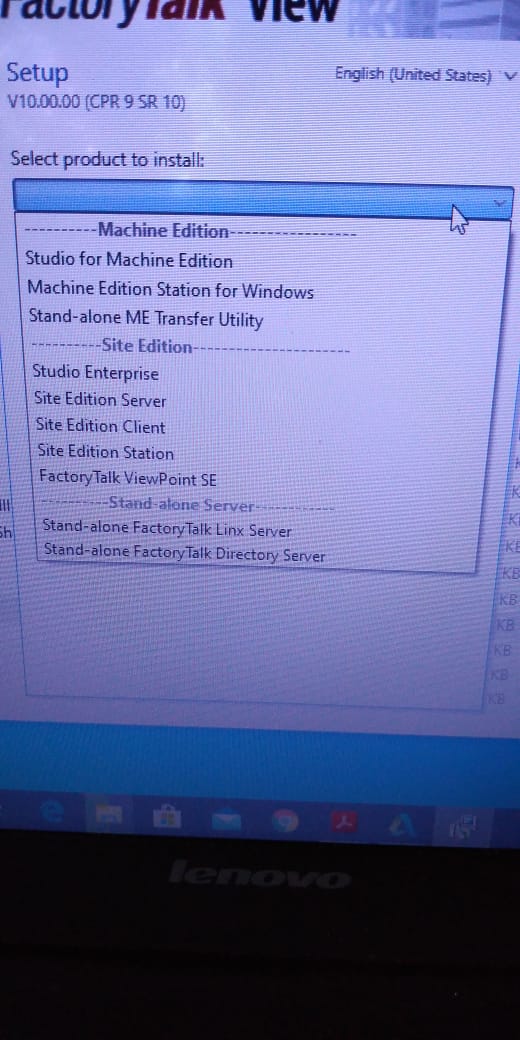
– Install Studio Enterprise this is a combination of all SCADA & it will work as per your licensing
– Does anybody here has experience with Toshiba relay GRL 200? – I want to ask about the IO config – Why don’t you Let the admin look into it? Please send me any study material regarding AVR – For a substation – Little emergency for my undergraduate project – I can send you the datasheet of Engine AVR – ABB Unitrol 1000
– I have to change CT/VT ratio in an Elster A1800 energy meter. Already got established communication with the meter via Metercat 3.5 software. I believe CT/VT ratios can be changed via the function “Program” but I am not able to proceed as everything at the “Program” popup window is grey (not editable), I request you support me in changing the CT/VT ratios. – You have to enable changing xt ratio on the parameters function
– There is no Parameter menu in Functions? please clarify in detail or send a snapshot – Hi Guys, I have a question for the 220KV level, which is suitable for either CVT or IVT(PT)? And why Usually we are adopting IVT(PT) in Andhra Pradesh India – CVT always – Sir can you please support your statement As we have observed the drift in secondary voltages is more in CVT compared to IVT over a time span – Mainly installation reasons. they are lighter, cheaper, and Safer (transfer of emf when a fault occurs) as there is no direct connection to the primary voltage source. – Can you explain how does the voltage drift? – Deterioration in the capacitance levels throughout operations results in variations in secondary voltages Can’t that be fixed during maintenance? (Note: I don’t have any experience in maintenance and operation Even I don’t have any experience in Maintenance. But I am not sure we can improve this ineffective manner) – CVT for transmission circuits or High Voltage i.e greater than 66kV and IVT for distribution circuits 33kV and below – Moreover, we are mostly using IVT in 220KV levels also so, I am not aware of fixing methods. I believe it’s a cost trade-off. In India IVTs in 220kV class are more affordable than CVTs. And yet you may see them actively used in 220kV stations where the transmission system is at 220kV level. This is because the same CVT would be used as a coupling capacitor for PLCC communications as well. – That’s my understanding – Why when we calculate short circuits at transformer secondary we should consider no-load ph to phase voltage not rated voltage?! – Yes.CVT is more affordable to be used since the consideration of its(equipment) isolation to H.V. – Yes, we can track and analyze its dissipation factor( Tan Delta measurement) – Which position? – This is an AVR relay from ZIV bringing. -anyone has the pin configuration of this relay? – If you mean bias setting, then I would say it has to be calculated based on the transformer parameters – Hello everybody, good morning. Do any of you run the digsilent program? – What /which are the switching operations and commissioning procedures of HV / EHV equipment considering the safety rules of power system operation? -P94V Undervoltage relay showing continuous trip, but no alarm present and all functions disabled, need technical support .can anybody please help? – Go to view record and reset led Did, but still not going – To increase the contact Resistance with the Ground!
– Why stone and whether it’s the only solution? – Cheapest – Another reason stones are used is because it helps in the fire. mitigation, especially where oil traps/ sump pumps are not available.
– The leaked oil will have less surface area exposed to air that can burn, thereby reducing the fire hazard. – Weather dry sunny temp 35c approximately Fault 132kv lighting arrestr and HV bush of power transformer 20/26MVA damaged – 132kv CT side clamp -Counter of lighting arrestr – Lighting arrestr – Structure damaged After fault jamper – Analysis as per our senior-most retired chief Engineer such type of fault occurs due to delay of lighting arrestr counter delay. This type of fault occurred in Pakistan time by a time when lightning arrestr having counters are installed. Due to the delay, the HV bush of the power transformer was also damaged – Did the Hv bushing pass the lighting impulse test? – At the time of manufacturing or now – Bushing may be damaged due to pressure of conductor available 132kv surge arrester if required plz context 03214484444 – I wonder if you have the fault recorder of this lighting surge impulse on your relay – Are there any lightning arresters at the top of the transformers firewall/ other location? – What’s the fault in the protection relay or fault recorder? – Ds agile documentation please, guys how can I get cooling oil for a 1000-volt transformer – What is the relay saturation of the IDMT curve in sepam T80 and S82?
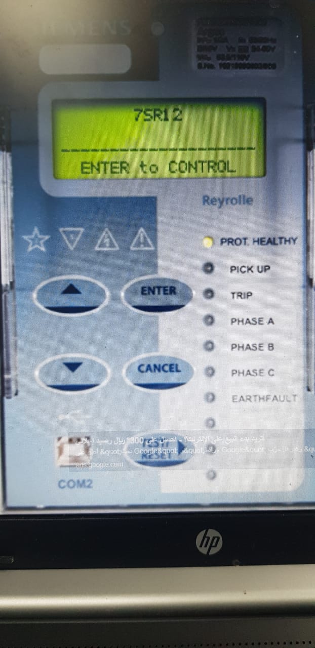
-Any have experience In Reyroll Relays.! I need help with how to change the “Out of service mode”.
– We need to do an 87L test, as you can see in the secondary current to relay is very low 0.044A. We did a second injection for the GE L90 relay and found it doesn’t read 0.044A. Value is fluctuating and gets stable at 0.1A.
– why the 51N protection of the REF615A relay operates in an almost constant time of 0.06 seconds – reviewing the operation curve the minimum operation time is 0.02 seconds at least the first 3 tests would have given me the correct value – check the other seating. Check the type of curve selected in the relay, Whether it is time or IDMT -1 group setting might be clashing with another one, check all stage settings group-wise. – Work Is for Automation Visit in Kolkata. Just visit the site in Kolkata only people from Kolkata plz contact me.
– A Power distribution full project including the design of LV and MV component – 40mva x-mer tripped on differential during charging of 33kv feeder with Idr= 0.49pu, Idy= 0.50pu and Idb,= 0.53pu. Both sides LA have physically verified and found ok. – Did you check the %of Harmonics during charging from the DR? – please do a stability test and after that examine the results.
– might anyone have the design book of transformers with CRGO steel core and amorphous metal core – Please guide how to reset DR full alarm in DPR Micom p442 Schneider Electric – Maybe you can right-click on the device and select supervise device
– Anyone has a VALANCE book on “How to Test Breaker Failure Element Logic”?
– I have a problem with Micom P443 for Distance Protection. I have a problem with System Checks for Autoreclose, anyone can tell me what is the difference between CS1 Close Enable dan C/S AR Immediate? – Cs1 close enable is the setting of sync check on which you want to recloser the circuit breaker like on Live Line Live Bus or Live bus Dead Line or Dead Bus. – If you enable c/s AR immediate then it means that if during the dead time system check conditions are met then it will reclose the breaker without waiting for the remaining dead time period, – Like for example if dead time is 1 sec – And system check conditions are met during 0.6 seconds of dead time, then the relay will give reclose command without waiting for the remaining 0.4seconds of dead time. But you have disabled the system check conditions on shot1 which means it will reclose the breaker without looking into any system check conditions, – Sys check on shot 1 should be enabled too.
– Hi Guys I have a question: what is the problem with a 3phases motor run by A frequency driver, if I want to run it very slowly for instance at 4HZ normally it runs at a modulated Frequency variable between 50Hz and 0 but what happens to a very low frequency? – I know that it will run slow, but it will warm up a lot right? but more than that what will it happen? somebody, some documentation to explain this phenomenon? – It depends on the loading. The higher its loading, the more power is needed to turn the output torque. If you don’t have a load, just make sure your lower frequency setting has a minimal current to move the rotor otherwise, it will overheat. – I even reinstalled my windows not going, I checked the internet settings also.
– how we can develop an HMI screen of operator name tag id selection in Schneider Vijeo Designer Basic HMI software – Can Anyone suggest or provide a link for low-cost alternatives for moxa U port 1150 type connectors with similar capabilities? – USB to Serial converter
– Does anyone have sft sav diagnostic software for the Sepam relay? – Does Anyone know about selec Twix-2 PLC communication with Schneider HMI – Please have someone ever configured SEL 487B busbar protection? – The SEL Technical Support Line is available at +1.509.338.3838
– does anybody here has the SUE3000 configuration tool – Some examples of End Fault Protection with SEL 487B?
– Anybody can please share with ME Schneider Software SFT SAV? – what does this number means 6000 of this RCD? – It can open currents up to 6000A. 6kA – Note it’s RCBO not RCD – What s the difference? Because some tell me it is the max number of trips. RCBO stands for residual current circuit breaker. It can open faults up to 6000A. It can be used for short circuit protection as well as sensitive faults of 30ma. RCD is a residual current device. It’s used only to pick up sensitive 30ma faults. They can’t open full short-circuit currents. -Think of RCBO as RCD+MCB – No it’s the rated fault level.
– We have the following problem with ER making DUOBIAS relay for Transformer differential protection – Can anyone guide what to be done with this? – Hi anyone tested the commissioning motor differential protection relay procedure please Sharing – Short circuit level for this device – This kind of error shows in sverker 900 Megger relay test kit anyone has an idea what is this?
– Maybe you could try to restart the device. And try jumper each phase RST to the neutral phase. – Jumper are arranged like this is it ok? – I have restarted the kit but it not working – Jumper I1to neutral, then I2 to neutral, and so on. Simultaneously inject a small current to monitor the device voltage ports are also not working – How about the current ports? -They are also not working – Make sure when you start the device the knob selector is in an off position. – Check the fuses too
– Does anyone know if you can force or simulate voltage on an ABB relay? That is, without using a device like Omicron – someone helps, how can I test the GE L90 diff relay as a stand-alone without connecting with another one? You can only force digital outputs and simulate inputs. You can’t force analog signals such as voltage and currents. You need an external source – I’ve never dealt with this relay but If it is for line differential, chances are that you’ll need two relays. the receiver and transmitter – But you can still use the primary injection method to do the testing – Do you have to test line differential? – You can go to setting, testing, channel test, and loopback. Inject currents, the relay will consider one current as local and one as remote
– Hello guys, I’d like to ask maybe some of you ever test this type of relay. – Where can we find the tms – I think tms is 2 – TMS is nothing but a round dial – Yes it is 2 – In this case, it’s 2
– for ref relay input problem. Ref620 – From the drawing, check the terminal point associated with this input. Isolate it then troubleshoot that circuit to find out where the “high/positive” signal is coming from – why does inside relay see this message drawing as not a problem?
– I am working with a 2X300 MW thermal power plant in India and our 400 kv switchyard is having Alstom MICOM P 441, and REL 670 for protection also for the generator we are having siemens make 7UM622 and MICOM p345. Is there any standard that speaks about the frequency of relay testing? – Normally frequency of Numerical Relay testing depends on the utility practices.
– In our utility, we do it annually. But in my opinion, it is not required annually. – Numerical relay can be tested for 5 years once. Scheme testing can be done annually. – anyone has a cracked version of IED smart or IED scout for the IEC 61850 simulation? – How to do scaling of this pressure sensor – these transmitters are of a fixed range – 615 series? -RET620 – try to use a new project. if still like that try to factory reset the IED but if it is still operating
– How to connect GPS to this siemens relay 7VE632 -synchronization via IRIG-B – someone assists me with CPC 100 software. – You either need IRIG B port on the GPS receiver or you need NTP to IRIG B converter
– Please find below the parameters you are expected to use as discussed with RTM; Reactance = 0.2215 ohm/km Inductance = 0.20808 ohm/km Suseptance = 0.07573 ohm/km Distance = 313km – Please how can I find the positive and zero sequence impedances from the above parameters thanks – 400 KVAR 90 UNITS. 132KV CAPACITOR BANK. neutral CT 5/5. 132kv CT 400/5. Capacitor protection or unbalanced relay current setting? Relay type SPAJ 160 C – Normally Unbalance protection has one special other CT different from CT 132kv phase or CT neutral but if This CT 5/5A is just for SPAJ protection we adjust the setting unbalance between 10 (..)20% In for nominal current this CT 5/5A
– Please explain the working of the reverse power relay at the consumer end for the small hydropower plant with a declared capacity 24.75 MWWhat is recommended Characteristic angle for Directional Earth Fault protection (67N) on SEPAM
-Sepam relay is on the closed-loop network. -System grounding: resistance grounded (Two NGR Prallelled: 2x800A: 1600A). The type used for 67N on Sepam: Type-02 (the protection function uses I0 vector magnitude). Residual Current input on Sepam: Calculation of Summation three-phase current (not residual CT).
– I want to know if my raw data for the sensor is 0 to 32767 and I wanted it to show in HMI in the format of 0 to 100 bcoz if in system sensor mistakenly gets faulty or I have to replace the sensor and the sensor of any other company in my system, so due to this I can change from HMI raw data in the format of 0 to 100 is it is possible?
– Hello, Micom p-243 protects the compressor after start 15 minutes then trip. The indication in local HMI (motor fault alarm )but in the protection relay no indication but became an open position. When I go to the record I see this in the pic – I do isolation resistance for the motor by using 5kv meggar the result was 4Gohm
– In HMI how to create an operator name error -It’s over Current, what’s your starter motor current start pick and protection Micom configuration? – Respected members, Please guide me on how to carry out the Hi-Pot Test/Dielectric strength test for 22kV 3ph Breakers/Bus bar. -If the available source is DC for testing, how much voltage is to be applied, and are any references of the standard for the same? – How to write scripting language for 0 to 50 Low and 50 to 100 high values in C programming for HMI?
– on Nari pcs9611 relay, when powered on it displayed sub-supervision Alarms. Alm-device, Alm -time sync. How can I cancel? – set the time synchronization to off instead of sntp – Under settings? – under device config or communication.
– Does anybody has ZX0 ABB switchgear O&M.manual – Especially Gas handling procedures – HB 600-05 en – HB 605 Gas handling Manual for ZX0 – I tested my lightning arrestor for 11KV after removing it from the line and the IR value was 400 meg. – A few minutes later I tested it again the value was raised to 15 Gig.
– Please I need the manual of Siprotec 7SA87 – Hello everyone, could you help me with the function of the TC1 on the delta winding? – It’s a current transformer for the winding temperature gauge
– someone knows what is the difference between I> and I>>? – I> is the short-time protection setting and I>> is the instantaneous protection setting of the overcurrent relay – Can somebody tell me what happened if the tripping coil resistance and a closing coil resistance of vcb are the same? then there is any impact on the performance of vcb? – You can return to the datasheet of the circuit breaker and closing and tripping coil, you can find the standard values of the resistance of the trip and closing coil and compare it to the measurement – I just want to know the theoretical answer Behind this. – From an electrical engineering point of view – closing coil resistance is designed much less than tripping coil resistance to having a stronger magnetic field – Yes I know it is designed, but my question is if they are the same then, what happened?
– does somebody here have some “how to configure Modbus protocol in SEL relays” document or some kind like that? – Someone has a method statement for Testing CVT Tan Delta
-Does anybody have a project for the RED670 relay? – Anything, in particular, you are after !’vv? – Current line differential relays fairly straightforward?
– Anyone knows what is the problem when a source (power plant) transmits power to a substation, then the neutral current monitored in the power meter is a bit higher than normal? – I know that It means that there is an unbalance current in each phase. But what else can be that causes the phenomenon? – The P.F on phases R and S are lagging 0.9, but phase T shows a leading P.F.
– In case it’s an internal fault, just assume that the 87 T relay and Ref relay will trip. – your understanding is correct. But apart from it, if primary Overcurrent (50/51P) works, it will trip the CB 150 kV, and how about the CB 20 kV? – Is it required to trip the CB 20 kV too? – 87T trip, REF not really, depending on the fault. PP fault or 3P internal fault won’t initiate REF – To isolate the power from the LV side too, in case of bus section on the 20 kV side is closed – Depends on the control scheme we use in most of the cases we adopt if HV side CB trips on protection LV CB also gets a trip, and REF is more sensitive for earth faults in the differential zone. If it is an earth fault REF trips faster than Diff. – I think that 20 kV CB will need to trip too to prevent reverse power from the remanent voltage (power) at Bus 20 kV side. But if there is a remanent voltage on the 20 kV side, is it possible to induce a voltage in the primary winding to create a current? – Since you have NGR, an earth fault close to neutral may not be detected by REF. – Percentage of the unprotected zone can be calculated based on relay settings and CT ratio. – Yes. due to the resistance, the sensitivity will be limited. – Have everyone ever tried the induced voltage on the secondary winding of step down Transformer i.e. let’s say 150/33 kV. How about the primary winding transformer, does it will generate a low current or a harmonic current? – Actually, fault moves towards the source. In actual LV will not trip because the fault current will move towards the source side (150kv) side but if inter trip function is available then LV 20kv side will trip too – Anyone knows about the calculation to get the value of Z1 Sensit? Iph>1 ? – Fault current should be above this value to identify zone 1 or zone 2 faults – I got it. But how to get this value? – Okay. I have found it was 1.2 x CCC / CT Ratio – CCC indicates which value? please clarify I doubt the Current Carrying Capacity Of the conductor – In Distance Relay – Anyone knows the CB IS( In-Service) Time function? – Since I close my CB then the IS time starts to count to set AR Block – If CB is manually closed then after this time CB will be considered in service and the Auto Recloser function will be enabled too. – But why it AR block indication appear? – After the CB IS Time starts to count. Still struggling on this distance relay – Because during CB IS time AR Function is disabled to block the AR on SOTF fault, change to ABB REL670 – What type of relay is this one? – P443 Micom – does anybody here has a p14d Modbus register – who knows the ZIV default password – Any ZIV relays specialist – Hello all, does anyone has a GRL 200 Toshiba Line Current Diff Manual Book? – Four corner numbers 7931
Join 20 WhatsApp groups for protection engineers
20 WhatsApp Groups for protection engineers
WhatsApp Grp 01: Protection Relay – General
WhatsApp Grp 02: Substation Automation – General
WhatsApp Grp 03: Transmission line protection
WhatsApp Grp 04: Transformer protection
WhatsApp Grp 05: Motor protection
WhatsApp Grp 06: Generator protection
WhatsApp Grp 07: Overcurrent and Earth Fault Protection
WhatsApp Grp 08: Busbar protection and Bay controller
WhatsApp Grp 09: Breaker protection and control
WhatsApp Grp 10: Protection Relay Testing and commissioning
WhatsApp Grp 11: DIgSILENT
WhatsApp Grp 12: ETAP
WhatsApp Grp 13: PSCAD
WhatsApp Grp 14: IEC 61850 configuration
WhatsApp Grp 15: Switchgear GIS & AIS
WhatsApp Grp 16: GE Relay Configuration
WhatsApp Grp 17: SIEMENS Relay configuration
WhatsApp Grp 18: Schnider Relay configuration
WhatsApp Grp 19: SEL Relay Configuration
WhatsApp Grp 20: ABB Relion configuration or more services
send a message to our WhatsApp support number, (Click)
Sample discussion:
– I have a Zivercom relay for the Tap changer. everything looks fine but it’s not Tapping who can assist tanks – is anyone familiar with Siemens Siprotec 4 7SD Line Current Differential Relay? For example, if one end of the relay is selected in Commissioning mode(test mode), will the remote end relay differential protection be in commissioning mode or test mode also? – Commissioning mode at one line end will not turn on commissioning mode automatically to another side. Plus commission mode is completely different from the test differential mode. – Can you explain a bit more about the test differential mode? Does turning the test differential mode at one end also activate the remote end’s test differential mode? – Anyone REM620 relay this message what problem – Anyone has the actual standard IEEE 485 or an excel sheet? I need to size the substation battery charger, please! – IEEE 485-2020?
– Does anyone know what these signals are used for? – Apparently, they are permissive to Switches – RECEPTION RRR, RRA, RRX, and RRY – the arrangement of the substation is as follows – Have anyone tested Cap bank differential protection in Siprotec 5 7SJ85 relay?
– constantly get this error while writing to the IED – delete the HMI page first – do the license update tool – Does anyone have software for this relay micom2.1? – I have found Micom software if anyone can give Ziv software as well plz Our substation incomer feeder is tripping downstream and upstream without any fault when switching on outgoing feeders. – Please suggest any ideas to solve the above-mentioned issues – What fault was recorded by the relay? – There is no fault on the relay but upstream and downstream are tripping when switching on any outgoing feeders.
To join our VEBKO WhatsApp group, plz text our support team on WhatsApp(Click)
– Any circular regarding the fair service life of various testing equipment in the power sector. – Hi, has anyone ever replaced these manual annunciator window tiles with a 3rd party tiles? or other alternatives? – We are facing this kind of rebooting issue with the AREVA Micom P742 peripheral Unit for busbar protection. Does anyone have any idea regarding this issue? How to overcome this?
– Can we use a 10 ac drive on a 15 hp motor? – 12.5 hp drive on 15 hp motor – Hi, do you guys ground the shield of control cables at both ends or only a single end? – Single-end – How about for CT VT Cable?
– May I know if would there be an issue if we use a CT with a high Burden (15VA for example) for a protection relay (microprocessor type). For the old mechanical type, I understand that the CT needs a higher burden to drive the armature – when I turn on the generator in this panel my generator has an unstable frequency but when I operate it manually the frequency stabilizes. what may be the cause of this? – Is your gen-set in synch with other gen? – no sir. What is voltage? – plz check the gain & another setting for your operator panel – 460v – there is no problem with the engine & gen-set itself it is the only problem with the operator panel feedback signal which will be generated as per setting – Cause freq regulation is in the generator itself not in Woodward – we try to bleed fuel on the generator. but nothing happened – I thought Woodward only does parallel synchronization and some protection functions but is only using small loads that’s why we don’t sync our generators. – I looked at the manual for easygen. There is a function of frequency control. I have the same system – But never got time to check every function in Woodward. – I do check some functions but the configuration has a password. the management told me that the supplier has the access to its unit.
– does anyone knows about arc resistance and tower footing resistance value for the 765KV transmission line?
– I need to disable goose controls in the REF 615 ABB relay. Is it possible from HMI? – who can assist me with an IED scout that’s licensed REG630 how to test method DOPPDPR function Power Angle setting anyone to have a formula – Could anyone be having transformer test guides preferably based on megger make test equipment? – Paci’s configurator from Schneider, can anybody have this software if yes kindly send me the link, it’s urgent please help me – Somebody has REX640 TERMINAL DIAGRAM? – Does anyone know how to choose a zero-sequence transformer? – In the VAMP300 relay display LED continues to glow without assigning, without mapping with DI points. what is the issue please kindly suggest!
– Need help in ABB RVC APFC Relay programming. – If anyone has a license for REB500. Can help me, please? – ABB normally does not release that license that allows you to configure 31etap 12:00 – abb pcm600: The user license there isn’t much you can do with it.
– Kindly someone tells me that in C264 Relay, how to change synchro-check parameters and find the passwords? – Connect to Cat tool to these devices n check network parameters. Trying to read the setting but the reading takes a few hours. Are there any solutions? – I assume some delays in the network..try connecting them one-to-one if possible. – Try to reboot the relay – what could be the problem if Generator Shuts Down on High or Over Frequency, Over Frequency Runaway – If you are connected to the grid Burn the rotor due to induced currents. If you are in islanders mode: damage the connected equipment.
– is it ok to run a generator that varies 59.9-60.1 frequency? – Trying to read ABB RET 670, but the messages show up like this – Any insights into this problem – Does anyone knows how to add delay time in VT Fail ABB RED 670 – Not very sure but An inconsistent state means the current values in PCM are not reflecting the IED values. If a reader does not resolve this try to see if there is a new version of PCM. – 132kV transformer HV breaker was closed on NO load and the LV breaker was open, but suddenly differential relay operates and gives a differential trip. In the fault study, the HV side current was 860 Amp. Somebody tell me what could be the reason? – For how much time the transformer was on no load? 132/11.5kV? -Approximately 10 to 15 minutes – MVA? -132/22 kV (wind power plant) – There must b some issue, – So this is not inrush – Do TTR and winding resistance, – If it is the newly commissioned plant then the issue will be in the relay setting otherwise check transformer winding. do the IR. – I did an excitation test @ 10 kV and the results were OK. – Plant is in operation for the last 4 years. You will have to do TTR and winding resistance to diagnose the matter, Hope you will get the problem by doing these tests,
– Any mechanical protection PRD, BUCH has operated. Did u retrieve the fault records from the relay? – TTR? – turns ratio test – No trip from mechanical protection. – In the fault record HV current was 860Amp and LV current was 0 amp. – Check the CT ratio adopted in the differential relay and what was the differential current setting adopted and actual current during the relay operation? – Transformer turns ratio
– 860AMP WAS A SINGLE PHASE OR TWO PHASES OR IN 3 PHASES? – In 3 phase – Did you check the lighting arrester AT 132 KV SIDE? – Yes surge arrestor can also be damaged or weakened, as you are using Yard CT for Differential protection – do also check your HV arrestors
– Can anyone help me with the PACiS configurator? – Physically that was OK, for counter I will check – Do hipot test of arrestors, which might be differential tripped because of arrestors, If u have a secondary injection kit like Omron or Freja plz do the secondary injection to know that there is no problem from the relay side. – can I ask why my plc doesn’t read flow? – Check that the analog signal is reaching from your flow meter to plc? – Check 4 to 20 amp signal
– Hello guys, does anyone know how to avoid distance trips when VT Fail occurred on 3 phases in REL 670? – Anyone has any material for Artificial intelligence application in Protection?
– Pls help me how to install PCM 2.10 – Strongly recommend installing on virtual machines – After 3~4 different versions, they always conflict and give errors. – I run different virtual machines on the ESXi hypervisor.
– I need help analyzing this Disturbance Fault Record whether it is due to Lighting or Flash. – It was a fault on Line Diff and Reclose on Phase R. – Plz tell me, what is relay coordination and what its functions are. – Line auto-reclosed successfully?
– We have 50/1 5p15 CT installed on a 33 kv feeder whose fault current initially was very less but now the Power supplier has installed a 50MVA transformer with 11% impedance 29etap08:55 – abb pcm600: And fault current is almost 8000Amps, I believe I need to upgrade protection CT to meet the high fault current – Can anyone suggest What’s the 33kv fault level? – Now it is 8000 amps. Fault current level 50 MVA transformer installed at state electricity board substation and we are consumers with 33 kv feeder voltage – 50MVA 220/33 KV star/ star connected transformer 11% impedance – Is the ct used only for over current and earth fault? – Yes 50,51, 50G, 51G – Strictly speaking, I would put 200/1 5P40 2.5 VA. However, if the relays have CT saturation detection, you could go lower. – What’s the relay being used? – P127 – Do you have the CT test results? In particular the DC resistance of the CT. -Can you give your consideration or calculations for this selection – So you need an accuracy limit factor of 40, with a low burden.
– you won’t need much burden as the relay is numerical and installed inside the switchgear – Your existing 50/1, 15 VA may actually work if you knew the DC resistance. – Do I have to check with the CT testing kit?? – I believe CT supplier should have this information – Yeah if you have test equipment (Omicron CR analyzer or similar) that should be easily possible – That’s possible, however normally the manufacturer will not specify the DC resistance for 5P/10P class acts. No harm in asking them though – CT’s Analyser – Ok I will check with him today, as I don’t have an omicron kit available nearby That is the only option I have
– How do you coordinate DC resistance with fault current? – So if Rct<= 1.75 ohm, you can use it For a 50/1 A ct this may be achievable. need to Replace 33 kv side CT with, 1000/1A, 5P10,15 VA With this approach, I’d reckoned to check the pickup values.
– Ynynd1 And tertiary (delta winding) are unloaded? – Then no issue transformer will follow the system phase sequence,
– What is the difference between IN-HV Deriv Angle and IN-HV Measd Angle on monitoring online? – Derived means the neutral current has been calculated by summation of IA, IB, and IC whereas measured means the neutral wire of ct secondary is connected to the neutral element of the relay, and it is being measured, – What is a dead zone in protection?? – Dead zone is the Zone between CT & Open CB. It’s the point not seen in the zone of protection that of a relay. If a fault occurs at this point, the relay will not issue a trip. Usually between CT and breaker – IN HV derive is neutral vector calculation, meanwhile In HV measured is a neutral REF winding – We cannot say it is neutral ref winding until we see the setting of the relay, – the setting of the wiring diagram is right. The relay and schematic drawing setting depict the connection of the ct secondary wires with the differential relay.


 DIGSI 5 Training€90