- Installing DIGSI 4
- Managing Projects
- Working with the Devices
- Optimizing Parameterization
Sample page of the file:
The first step is to create a new project. The DIGSI Manager has been started, a project dialog box has not yet been opened.
Click File- New of the menu bar, enter a new project name and confirm with OK.
The project dialog box is displayed.
Names and symbols of all project containers are displayed in a hierarchical tree structure. To put it less complicated, we could say that containers are displayed. This pane is called a tree view. An opened folder is the first symbol to be displayed in this pane. The opened folder is designated as project 1 and represents the top level, the project itself.
The right pane of the window shows a folder-type object. If the DIGSI 4 Remote program is installed, a phone book type object and modem type object each are displayed in addition. Otherwise, this pane of the window continues to remain empty. This page serves to display further names of symbols of objects, which are contained in one of the selected containers of the tree view. To put it less complicated, we could say that this pane shows objects. Since the right pane of the window is represented as a list, this structure is called a list view.
Up to four objects are first automatically created within a new project of the tree view.
– Project (cannot be inserted manually)
– Folder (to structure a project)
– Phone Book (station addresses for a modem connection)
– Modem (for the communication SIPROTEC between your computer and the SIPROTEC 4 device
modem connection for the storage of modem profiles).
Phone Book and modem will be created automatically if the DIGSI 4 Remote component has been loaded.
The SIPROTEC 4 device object type represents a real SIPROTEC 4 device with all its setting values and process data.
The V3/V2 device object type serves to create shortcuts linked to the V3/V2 devices within the project structure. These device data are processed with DIGSI-V3.x.
The SIPOROTEC 4 version object type is created to document different parameter settings groups of a SIPROTEC 4 device. The device address (VD number) of the corresponding versions is identical to that of the original device.
The left window pane contains the names and symbols of all project containers in a hierarchical tree structure.
The right window pane displays the objects of the selected folders. The structure is designated as a list view.
Your first step to creating a system-specific project structure is to insert folder-type blank containers in the corresponding levels.
Click a folder object to insert a subordinate folder via the menu command ® Paste. A maximum of 9 levels is the permissible hierarchy depth.
Several objects can be juxtaposed in parallel.
The names of the folders can be renamed to easily adjust to the requirements of your operation.
As a first step, you create a new project. The DIGSI 4 Manager is started, no project window is open.
- Click File ® New in the menu bar.
- In the New dialog box, enter Project 1 as a name for the new project.
Don‘t modify any other settings. - Click OK.
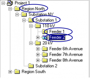
The project window is now displayed in the working range. Put it to full size. - An object of the type Hierarchical level is inserted automatically upon creating a new project.
- Click this object and then click the selected name. Enter Region Nord as a new name.
- Right-click an existing hierarchical level and insert the lower-level hierarchical level via the context menu Insert new object ® Hierarchical level. Enter the new name.
- Click a hierarchical level, e.g. Feeder 1, and open the device catalog via the context menu.
- Select the device and draw it on the hierarchical level.
The Device Catalog shows all SIPROTEC 4 devices available (installed) in the DIGSI 4 Manager.
The device catalog is an independent item. When you open the catalog, a button is created in the taskbar by Windows. The device catalog can remain open while working with the DIGSI 4 Manager to install all required SIPROTEC 4 devices.
Select a folder type object and click View ® Device Catalog to open the Device Catalog window.
The device catalog has a structure. Clicking a plus sign or double-clicking a folder icon will open the subordinate level.
For example, if you double-click 7SJ (time overcurrent protection), all installed SIPROTEC 4 devices with the device type names and the variant numbers will be displayed.
Short technical information is displayed on the lower catalog border for each device selected.
Note: Devices cannot be placed directly underneath the project folder!
The MLFB tab serves to determine the order number of the selected SIPROTEC 4 device in DIGSI 4. The order number is the code for the type and variant of the SIPROTEC 4 device. The order number is called the MLFB number.
Order number determination in DIGSI 4 affects all further parameterization options. Identical MLFB numbers are necessary for the communication between the DIGSI 4 device operation and the connected SIPROTEC 4 device. This is checked when setting up the connection.
The MLFB tab contains several drop-down list boxes. The drop-down list boxes related to the selected SIPROTEC 4 device are activated, only. These drop-down list boxes serve to select the order numbers to define the SIPROTEC 4 design and type in DIGSI 4.
As a first step, create a new project. The DIGSI 4 Manager is started, no project window is open.
Click File ® New in the menu bar.
- In the New dialog box, enter Project 1 as a new project name.
Don‘t change any other settings. - Click OK.
The project window is now displayed in the working range. Put it to full size.
When creating a new project, an object of the type Hierarchical level is inserted automatically.
Properties like object name, comment, or date of creation, have been assigned to all objects (General tab).
Some properties only refer to certain objects, for ex. the MLFB number for the SIPROTEC 4 devices or the device communication settings.
The values of the majority of the properties can be changed.
Select the object and click the View ® Details menu item to display the object properties. You can also open the Object Properties dialog box via the context menu or via the menu item Edit ® Object Properties.
If the property values are grayed, they cannot be changed. Depending on the entries you made in other text boxes, such text boxes may be activated. Property values in white/empty text boxes can be edited.
DIGSI 4 training pack