  • Trainer: Dr. Saeed Roostaee
  • Comment on this post or contact us for more details
  • Duration: 4 days
  • Type: Face to face

Parts of the course topics:

⦁ Introduction to power system
⦁ The Per-Unit System
⦁ Per Phase Analysis
⦁ Symmetrical Components
⦁ Fourier Transform signal
⦁ Faults in Electrical System
⦁ Consequences of SC Faults
⦁ Types of Electric Faults
⦁ Establishment of SC
⦁ SC Calculation IEC 60909
⦁ Typical Fault criteria
⦁ Intro Power Sys Protection
⦁ Electromechanical Relays
⦁ Numerical Relays
⦁ Current Transformers
⦁ Voltage Transformers
⦁ Overcurrent
⦁ DOC (ANSI 67)
⦁ Coordination
⦁ Earthing
⦁ Line-To-Ground Faults
⦁ Earth Fault 50N 51N
⦁ Sensitive Earth Fault 50Ns 67Ns
⦁ Power Transformer Faults
⦁ Winding & Terminal Failures
⦁ The Effect of Through Faults on Power Transformers
⦁ Tap Changer (OLTC) Failure
⦁ Transform Miscellaneous Failures
⦁ How do we Protect Transformers?
⦁ ABB RET 670
⦁ Differential Protection
⦁ Transformer Differential Protection
⦁ Differences between digital transformer differential relays
⦁ Simulate different cases and test the differential transformer protection function
⦁ Restricted Earth Fault Protection(REF) in Transformer
⦁ High Impedance Restricted Earth Fault Protection working principle
⦁ Stability Resistance and Metrosil Resistance in REF Protection
⦁ Low impedance REF
⦁ Transmission Lines
⦁ Line Constants
⦁ Transmission Line Faults
⦁ How do we Protect Transmission Lines?
⦁ Distance Protection for Transmission Lines
⦁ Earth-Faults and Fault Resistance
⦁ Residual Compensation Factors
⦁ Short Zone
⦁ STUB
⦁ SOTF
⦁ Power Swing
⦁ Tele-Protection and weak infeed
⦁ Fault locator
⦁ Line diff
⦁ ABB REL 670

sdr


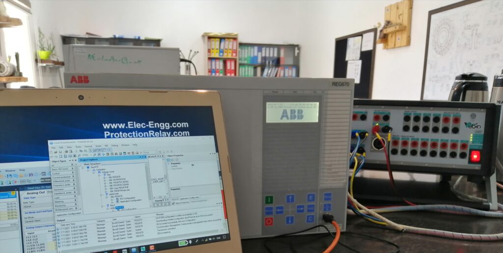
⦁ An overview of the PCM 600 functionality as well as how to get the software
⦁ Communication and Project setup, establish communication between the physical IED and PCM 600, Manage project with PCM 600, Hardware configuration
⦁ How to use the Application configuration tool in the PCM 600
⦁ How to use the Graphical Display editor tool in the PCM 600
⦁ How to use the Read and Write tool in the PCM 600
⦁ How to use the user management in the IED and PCM 600
⦁ IED online monitoring, event viewer, signal monitoring, disturbance handling
⦁ signal matrix editor tool in the PCM 600
⦁ The parameter setting tool in the PCM 600
⦁ Writing configuration into IED
⦁ IED compare
⦁ Config a simple distance protection function (SMAI, SMBI, SMBO, ZMMAPDIS, ZMMPDIS, FUFSPVC, …), configure sample signals based on the 7SA diagram
⦁ Config a simple 67N protection function, config disturbance reports (ARDAR, BRDAR, LED)
⦁ Parameter settings, XRIO format
⦁ Product guide for a pre-configured distance relay, and ordering, and modifying pre-configured distance relay based on our projects, Analog inputs (current &s for voltage), Distance Protection functions, and Communication logic
⦁ Current and Voltage protection functions and Earth Fault Protection Communication logic, Circuit Breaker Autorecloser and Tripping logics, Signal Logic and General IED functions, Virtual Binary inputs and outputs, Disturbance report analog and binary inputs
⦁ Function Block ActiveGroup
⦁ Function Block CMMXU
⦁ Function Block DRPRDRE
⦁ Function Block FXDSIGN
⦁ Function Block INTERRSIG
⦁ Function Block LEDGEN
⦁ Function Block LHMICTRL , LocalHMI
⦁ Function Block SINGLECMD
⦁ Function Block SMBI
⦁ Function Block SMBO
⦁ Function Block TESTMODE
⦁ Function Block TIMEERR
⦁ Function Block TIMER
⦁ ABB RET 670 Transformer Protection Application Template
⦁ ABB RET 670 Configuration and T2WPDIF Function block
⦁ ABB RET 670 Parameters and T2WPDIF parameters
⦁ Simulation of the differential protection algorithm in the ABB RET 670 relays


⦁ Omicron Test Universe Start page
⦁ Omicron Test Universe General settings
⦁ Omicron Test Universe Phasor view, Impedance view
⦁ Omicron CMC Hardware connection
⦁ Omicron Test Universe Test object, Overcurrent RIO block, testing of overcurrent
⦁ Omicron Test Universe Settings of the Overcurrent test module
⦁ Omicron Test Universe Diff parameters
⦁ Omicron Test Universe Diff RIO block
⦁ Omicron Test Universe Diff configuration
⦁ Omicron Test Universe Diff Operating Characteristic
⦁ Omicron Test Universe Diff Trip Time Characteristic & Diff Harmonic Restraint
⦁ RIO and XRIO history and why we should use this format for relay testing, RIO structure, XRIO structure, Differences between RIO and XRIO files, XRIO features & benefits, LinkToXRIO
⦁ XRIO template, How to Import Relay Settings, How to find a proper XRIO template and filter based on the relay
⦁ Common problems while loading the relay settings into a template and how to solve the issues, XRIO template based on the relay versions
⦁ Explain a case study XRIO file
⦁ Modify a case study XRIO file
⦁ Modify the XRIO template, RIO blocks
⦁ Distance RIO block
⦁ Advance Distance Test Module settings
⦁ Distance protection function principal, Impedance View
⦁ Analysis of several faults visually in the impedance view
⦁ Analysis of several distance relays (RAZOA, ABB REL670, SEL421, Siemens 7SA8x, MiCOM P442, NR PCS 931S, Protecta)
⦁ Distance Test Module settings
⦁ Preparing XRIO file for testing of impedance protection functions

Information

  • Course Name: SIPROTEC 5 and DIGSI 5 (advanced)
  • Trainer: Dr. Saeed Roostaee
  • Format: Pre-recorded videos (demo is available)
  • Course creation: June 2023
  • Last update: July 2023

Note: This course can also be held either Online or Face to face based on the request

Course Structure:

  • Module 1: SIPROTEC 5 Hardware and ordering
  • Module 2: Starting with DIGSI 5
  • Module 3: Working with SIPROTEC 5 in online mode
  • Module 4: System Functions
  • Module 5: Function Groups
  • Module 6: SIPROTEC 7SJ8
  • Module 7: SIPROTEC 7SA8
  • Module 8: SIPROTEC 7UT8
  • Module 9: SIPROTEC 7SS8
  • Module 10: SIPROTEC 7SK8
  • Module 11: SIPROTEC 7VK8
  • Module 12: SIPROTEC 7SD8
  • Module 13: SIPROTEC 7SL8
  • Module 14: SIPROTEC 7SX8
  • Module 15: SIPROTEC 7UM8
  • Module 16: SIPROTEC 7MD8
  • Module 17: Functions and Settings
  • Module 18: Signals and Masking IO
  • Module 19: CFC
  • Module 20: Control Functions
  • Module 21: Display Page configuration
  • Module 22: Functional Tests
  • Module 23: Measured Values
  • Module 24: Power Quality
  • Module 25: Supervision
  • Module 26: Communication
  • Module 27: IEC 61850
  • Module 28: Digital Twin
  • Module 29: Case Study 7UT8
  • Module 30: Case Study 7VK8
  • Module 31: Case Study 7SA8
  • Module 32: Case Study 7SS8

Course Details (Note: This part is continuously updating)

Module: SIPROTEC 5 Hardware and order

  • SIPROTEC5 Hardware
  • DIGSI 5 installation and DDD
  • General Settings
  • DIGSI 5 User interface
  • New project + Add device (Offline)
  • Modify the order code in the SIPROTEC online configurator
  • SIPROTEC 5 Online Configurator
  • Function Point
  • SIP 5 Configuration Procedure

Module: Online & Working with SIPROTEC 5

  • Connect to SIPROTEC 5
  • Indications
  • Fault Recording
  • Log
  • Reading Indications on the On-Site Operation Panel
  • Reading Indications from the PC with DIGSI 5
  • Displaying Indications
  • Operational Log
  • Fault Log
  • Switching-Device Log
  • Ground-Fault Log
  • Setting-History Log
  • User Log
  • Security Log
  • Device-Diagnosis Log
  • Communication Log
  • Communication-Supervision Log
  • Motor-Starting Log
  • Saving and Deleting the Logs
  • Spontaneous Indication Display in DIGSI 5
  • Spontaneous Fault Display on the On-Site Operation Panel
  • Stored Indications in the SIPROTEC 5 Device
  • Resetting Stored Indications of the Function Group
  • Test Mode and Influence of Indications on Substation Automation Technology
  • Changing the Transformation Ratios of the Transformer on the Device

Module: System Functions

  • Sampling-Frequency Tracking and Frequency Tracking Groups
  • Text Structure and Reference Number for Settings and Indications
  • Processing Quality Attributes
  • Protection Communication
  • Date and Time Synchronization
  • User-Defined Objects
  • Device Settings
  • Data Types
  • Function Control
  • Connection Examples
  • Chatter blocking
  • Settings-Group Switching

Module: Function Groups

  • Voltage current 3-Phase
  • Circuit-breaker
  • Process Monitor
  • Voltage-current 1-phase
  • Motor
  • Line
  • Voltage 3-Phase
  • Analog Units
  • User-Defined Function Group
  • Recording
  • Motor Monitor
  • Current-Flow Criterion
  • Circuit-Breaker Condition for the Motor
  • Closure Detection
  • Motor-State Detection
  • Cold-Load Pickup Detection
  • Thermal Replica Rotor
  • Capacitor Bank

Module: Functions and Settings

  • Power-System Data
  • Overcurrent Protection, Phases
  • Overcurrent Protection, Ground
  • Line Differential Protection
  • Stub Differential Protection
  • Restricted Ground-Fault Protection
  • Distance Protection with Reactance Method (RMD)
  • Distance Protection with Classic Method
  • Impedance Protection
  • Power-Swing Blocking
  • Teleprotection with Distance Protection
  • Universal Teleprotection with Distance Protection
  • Ground-Fault Protection for High-Resistance Ground Faults in Grounded Systems
  • Teleprotection with Ground-Fault Protection
  • Universal Teleprotection with Ground-Fault Protection
  • Echo and Tripping in the Event of Weak Infeed 874
  • Tripping with Missing or Weak Infeed According to French Specification
  • External Trip Initiation
  • Automatic Reclosing Function
  • Directional Overcurrent Protection, Phases
  • Positive-Sequence Overcurrent Protection
  • Instantaneous High-Current Tripping
  • Group Indications of Overcurrent Protection Functions
  • Overcurrent Protection, 1-Phase
  • Voltage-Dependent Overcurrent Protection, Phases
  • Sensitive Ground-Fault Detection
  • Non-Directional Intermittent Ground-Fault Protection
  • Directional Intermittent Ground-Fault Protection
  • Negative-Sequence Protection
  • Directional Negative-Sequence Protection with Current-Independent Time Delay
  • Undercurrent Protection
  • Overvoltage Protection with 3-Phase Voltage
  • Overvoltage Protection with Positive-Sequence Voltage
  • Overvoltage Protection with Negative-Sequence Voltage
  • Overvoltage Protection with Positive-Sequence Voltage and Compounding
  • Overvoltage Protection with Zero-Sequence Voltage/Residual Voltage
  • Overvoltage Protection with Any Voltage
  • Undervoltage Protection with 3-Phase Voltage
  • Undervoltage Protection with Positive-Sequence Voltage
  • Undervoltage Protection with Any Voltage
  • Rate-of-Voltage-Change Protection
  • Undervoltage-Controlled Reactive-Power Protection
  • Voltage-Comparison Supervision
  • Fault Locator
  • Fault Locator Plus
  • Over frequency Protection
  • Under frequency Protection
  • Rate of Frequency Change Protection
  • Under frequency Load Shedding
  • Phase-Sequence Switchover
  • Instantaneous Tripping at Switch onto Fault
  • Thermal Overload Protection, 3-Phase – Advanced
  • Thermal Overload Protection, 1-Phase
  • Temperature Supervision
  • Circuit-Breaker Failure Protection
  • Circuit-Breaker Restrike Protection
  • Out-of-Step Protection
  • Inrush-Current and 2nd Harmonic Detection
  • Power Protection (P, Q), 3-Phase
  • Current-Jump Detection
  • Voltage-Jump Detection
  • Vector-Jump Protection
  • Arc Protection
  • Voltage Measuring-Point Selection

Module: Specific Functions

  • Current-Unbalance Protection for Capacitors, 1-Phase
  • Peak Overvoltage Protection for Capacitors
  • Motor-Starting Time Supervision
  • Motor Restart Inhibit
  • Load-Jam Protection Motor
  • Thermal Overload Protection, Rotor

Module: Control Functions

  • Introduction
  • Switching Devices
  • Switching Sequences
  • Control Functionality
  • Synchronization Function
  • User-Defined Function Block [Control]
  • CFC-Chart Settings
  • Tap Changers
  • Voltage Controller
  • Point-on-Wave Switch

Module: Functional Tests

  • Direction Test of the Phase Quantities
  • Functional Test Protection Communication
  • Functional Test of the Line Differential Protection
  • Functional Test for Overvoltage Protection with Zero-Sequence Voltage/Displacement Voltage
  • Primary and Secondary Tests of the Circuit-Breaker Failure Protection
  • Circuit-Breaker Test
  • Out-of-Step Protection Function Test
  • Functional Test of the Inrush-Current Detection
  • Functional Test of the Trip-Circuit Supervision
  • Power-Swing Blocking Functional Test
  • Functional Test for the Phase-Rotation Reversal
  • Functional Test for Overvoltage Protection with Zero-Sequence Voltage/Residual Voltage
  • Directional Testing for Isolated or Resonant-Grounded Systems
  • Primary and Secondary Testing of the Synchronization Function
  • Commissioning Hints for Voltage Control

Module: Measured Values

  • Operational Measured Values
  • Fundamental and Symmetrical Components
  • THD and Harmonics
  • Minimum/Maximum Values
  • Average Values
  • Energy Values
  • Circuit-Breaker Monitoring
  • Statistical Values of the Primary System

Module: Power Quality

  • Voltage Variation
  • Voltage Unbalance
  • THD and Harmonics
  • Total Demand Distortion

Module: Supervision

  • Resource-Consumption Supervision
  • Supervision of the Secondary System
  • Supervision of the Device Hardware
  • Supervision of Device Firmware
  • Supervision of Hardware Configuration
  • Supervision of Communication Connections
  • Error Responses and Corrective Measures
  • Group Indications

Module: IEC 61850

  • External Signals
  • Quality Processing/Affected by the User for Received GOOSE Values
  • Quality Processing/Affected by the User in CFC Charts
  • Quality Processing/Affected by the User in Internal Device Functions

More info and update about this course: Contac us

To participate in this face-to-face / online training course: contact us

Course Title & Dates

  • Config and testing of the generator, transformer, line, and motor protection functions
  • 4 days

Trainer Profile

Registration

email: saeed61850@gmail.com

Tentative Course Schedule

Day 1
  TIME 

TRAINING SCHEDULE & TOPICS

9.00am – 10.30amABB relays, PCM 600 installation, Connectivity pack installation, Hardware configuration, Application configuration, Signal matrix Parameter setting, IED read and write IED online monitoring and signal monitoring Disturbance, and event viewer
10.30 am – 10.45 amTEA BREAK
10.45am –1.00pm  SIPROTEC 5 relay families and applications DIGSI 5 and device driver installation SIPROTEC 5 configurator Relay configuration
1.00pm – 2.00pmLUNCH
2.00pm –3.30pm    SIPROTEC 4 Relay families DIGSI 4 installation Masking I/O CFC Fault Recorder
3.30pm – 3.45pmTEA BREAK
3.45pm – 5.00pm    MiCOM relays range, naming, and application Easergy Software Configuration and PSL Event and disturbance recorder

Day 2

  TIME 

TRAINING SCHEDULE & TOPICS

9.00am – 10.30am    OMICRON CMC Test universe softwareAMT105  AMPro software signal view, impedance view, vector view different types of test modulesRIO, XRIO, and PTL
10.30 am10.45 amTEA BREAK
10.45am – 1.00pm        Principle of Differential Protection87G Generator Differential Protection87T Trans. Differential Protection87M Motor Differential Protection87L Line Differential Protection
1.00pm – 2.00pmLUNCH
 2.00pm – 3.30pm    Testing of the Differential protection function (87G, 87T, 87M, 87L) Operating CharacteristicDifferential ConfigurationDifferential trip time-harmonic
3.30pm – 3.45pmTEA BREAK
3.45pm – 5.00pm    81O Over frequency Protection81U Under frequency Protection59 Overvoltage Protection27 Under voltage ProtectionTesting of the Over/under frequency (81O/ 81U)Testing of the Over/Under voltage (59, 27)
contact us to reserve your seat

Day 3

  TIME 
TRAINING SCHEDULE & TOPICS

    9.00am – 10.30am    50/51 Overcurrent protection50N/51N earth fault protection 67/67N Directional/ directional earth fault protectionRelay coordination
10.30 am – 10.45 amTEA BREAK
    10.45am – 1.00pm        Overcurrent test moduleOvercurrent RIO block settings of the Overcurrent test module testing of the Overcurrent and Directional Overcurrent Functions (67, 67N, 50, 51, 50N, 51N)
1.00pm – 2.00pmLUNCH
2.00pm – 3.30pm    46 Negative Phase Sequence Protection51V Voltage-Dependent O/C Protection49S Stator Overload Protection49R Overload Protection48 Motor starting time supervision51L lock rotor
3.30pm – 3.45pmTEA BREAK
 3.45pm – 5.00pm    Testing of the Negative Phase Sequence ProtectionTesting of the ANSI 51V Voltage-Dependent O/C ProtectionTesting of the ANSI 49 Overload Protection


Day 4

  TIME 
TRAINING SCHEDULE & TOPICS

9.00am – 10.30am  Distance protection line simulation in PSCADTesting of the fault location function
10.30 am – 10.45 amTEA BREAK
10.45am – 1.00pm      21 Line distance protection40G Field Failure Protection21G Generator Under impedance Protection78 Pole Slipping Protection
1.00pm – 2.00pmLUNCH
 2.00pm – 3.30pm    Distance RIO block shot Test, Check Test, Search Test, Z\t Diagram, Zone SettingsTesting of the Distance function (21)Testing of the 40G Field Failure Protection
3.30pm – 3.45pmTEA BREAK
 3.45pm – 5.00pm    64S Generator, 95% &100% Stator Earth Fault Protection, 51/27 Generator, Dead Machine Protection, 24G Generator, Over flux Protection, 47G Generator, Fuse Failure Supervision, 32R Generator, Reverse Power Protection
  • Distance Protection
  • Differential Protection
  • Busbar Protection
  • Generator Protection
  • Restricted Earth Fault Relays
  • Back up Relay

Our Video Training Products:

MICOM P123 protection relay has been made to control and protect current and ground faults for overhead and cable lines, and MICOM P441 is one of the distance relays that’s responsible for protection control and monitoring of transmission lines.

Through this course, you can learn how to configure and work with these relays.

  • Online video training
  • Trainer: Dr. Saeed Roostaee (Profile)
  • 4 hrs pre-recorded videos + 4 hrs attached supplementary videos on google drive + data models + PDF files

Part 01: MiCOM relays range, naming, and application

Parts 2-7: exercises with MiCOM P123 and AMT105 setup. Three-phase signals are injected into the relay to test hardware connection and protection functions.

Parts 8-17: exercises with MiCOM P441 and AMT105 (configuration and PSL, event and disturbance recorder, overcurrent protection, voltage protection, negative sequence protection, and distance protection parameters)

Supplementary files attached

  • 01- start working with Easergy Studio in online mode
  • 02- MiCOM Relay Measurements, Event Logs & Disturbance Records
  • 03- Input naming in the Micom relays
  • 04- Communicate with MiCom P139
  • 05- Communicating with MICOM P139 checking the parameters from the front panel
  • 06- Binary input test from MICOM P139 front panel
  • 07- Binary input test from MICOM P139 front Easergy studio
  • 08 Function Parameters in the MICOM P139
  • 09- Overcurrent Function test in the Micom P139
  • 10- Inverse time overcurrent function IDMT test in the MiCOM P139
  • 11- CBF function config and parameters in the Micom P139
  • 12- Autorecoser function config in the MiCOMp139
  • 13- Autorecoser function test in the MiCOMp139
  • 14- Autorecoser function test in the MiCOMp139 By FREJA
  • 15- Under and Over Voltage protection function parameters and testing in the MiCOM P443
  • 16- Overcurrent and Earth Fault protection function parameters and testing in the MiCOM P443
  • 17- DEF protection function parameters and testing in the MiCOM P443
  • 18- Auto recloser function test in the MiCOM P546
  • 19- Trip Scheme in the Micom P546
  • 20- SOTF in the Micom P546
  • 21- MICOM P546 Differential protection test
  • 22- MICOM P546 Syncro Check
MiCOM P123 front panel
Easergy Studio

Certificate of Completion

After activating the MiCOM training pack on your system, we will issue your certificate for the course.

This course contains the following topics:

  1. Distance Protection for transmission lines: part 1
  2. Symmetrical Components
  3. Distance Protection: Earth-Faults and Fault Resistance
  4. Residual Compensation Factors: K0 and RE/RL, XE/XL
  5. Distance Protection for transmission lines: part 2
  6. Distance Protection: Earth-Faults in Isolated and Resonant Grounded Systems
  7. Distance Protection: Negative Sequence Direction measurement
  8. Distance Protection: Tele-Protection and weak infeed
  9. Distance Protection Power Swing
  10. Distance Protection Monitoring Functions
  11. Distance Protection Series Compensated Lines
  12. Fault locator with 2 ended measurement
  13. Earth Fault protection
  14. Auto Re-close and Sync Check
  15. Distance Protection OHL Setting Example