
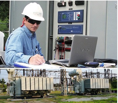
MICOM P123 protection relay has been made to control and protect current and ground faults for overhead and cable lines, and MICOM P441 is one of the distance relays that’s responsible for protection control and monitoring of transmission lines.

Through this course, you can learn how to configure and work with these relays.

  • Online video training
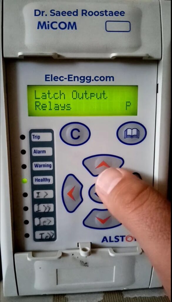
  • Trainer: Dr. Saeed Roostaee (Profile)
  • 4 hrs pre-recorded videos + 4 hrs attached supplementary videos on google drive + data models + PDF files

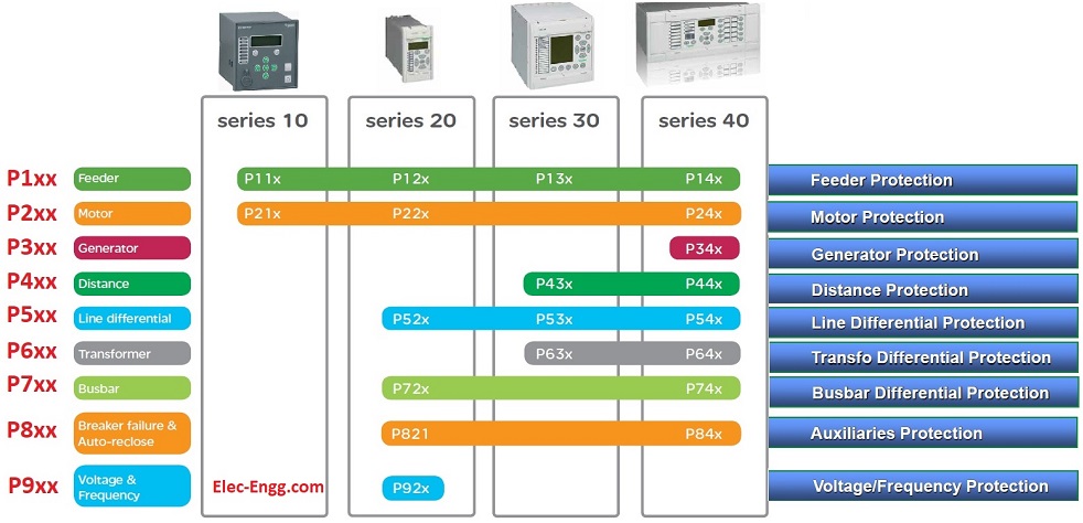
Part 01: MiCOM relays range, naming, and application

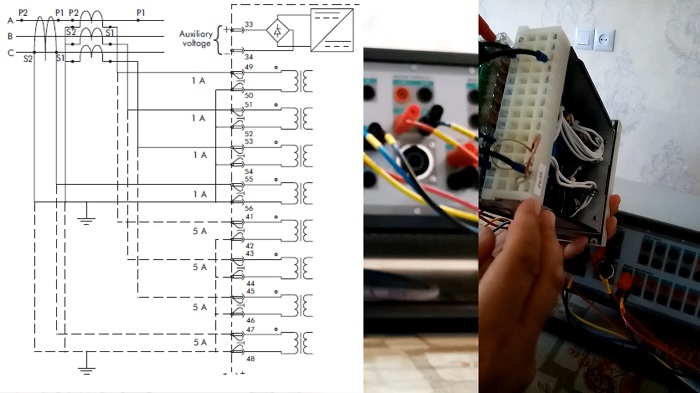
Parts 2-7: exercises with MiCOM P123 and AMT105 setup. Three-phase signals are injected into the relay to test hardware connection and protection functions.

Parts 8-17: exercises with MiCOM P441 and AMT105 (configuration and PSL, event and disturbance recorder, overcurrent protection, voltage protection, negative sequence protection, and distance protection parameters)

Supplementary files attached

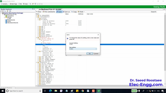
  • 01- start working with Easergy Studio in online mode
  • 02- MiCOM Relay Measurements, Event Logs & Disturbance Records
  • 03- Input naming in the Micom relays
  • 04- Communicate with MiCom P139
  • 05- Communicating with MICOM P139 checking the parameters from the front panel
  • 06- Binary input test from MICOM P139 front panel
  • 07- Binary input test from MICOM P139 front Easergy studio
  • 08 Function Parameters in the MICOM P139
  • 09- Overcurrent Function test in the Micom P139
  • 10- Inverse time overcurrent function IDMT test in the MiCOM P139
  • 11- CBF function config and parameters in the Micom P139
  • 12- Autorecoser function config in the MiCOMp139
  • 13- Autorecoser function test in the MiCOMp139
  • 14- Autorecoser function test in the MiCOMp139 By FREJA
  • 15- Under and Over Voltage protection function parameters and testing in the MiCOM P443
  • 16- Overcurrent and Earth Fault protection function parameters and testing in the MiCOM P443
  • 17- DEF protection function parameters and testing in the MiCOM P443
  • 18- Auto recloser function test in the MiCOM P546
  • 19- Trip Scheme in the Micom P546
  • 20- SOTF in the Micom P546
  • 21- MICOM P546 Differential protection test
  • 22- MICOM P546 Syncro Check
MiCOM P123 front panel
Easergy Studio

Certificate of Completion

After activating the MiCOM training pack on your system, we will issue your certificate for the course.

This technical report refers to the electrical protection of all 132kV switchgear. These settings may be re-evaluated during the commissioning, according to actual and measured values. Protection selectivity is partly considered in this report and could be also re-evaluated. The names of parameters in this calculation may differ from those in the appropriate device.

Technical Data of the Lines

Main Line
Conductor TypeACSR Lynx
Length27.8 km
TypeZM Type Tower
Positive sequence impedance 0.1583 + j0.4004 (0.431 ∠68.4°) Ω/ km
Zero sequence impedance0.3246 + j1.228 (1.27 ∠75.2°) Ω/ km
Current capacity (A)487
Next Line
Conductor TypeACSR Lynx
Length36 km
TypeZM Type Tower
Positive sequence impedance 0.1583 + j0.4004 (0.431 ∠68.4°) Ω/ km
Zero sequence impedance0.3246 + j1.228 (1.27 ∠75.2°) Ω/ km
Current capacity (A)487
SEL 311 – Line Protection

Protection Settings Calculations for Lines

SEL-311C Distance Protection Settings
Distance Zone
Non-Homogeneous Correction Angle
Load Impedance and Load Encroachment
Power Swing Detection/ Out of Step Detection
Switch on to Fault (SOTF)
Fuse failure scheme OR Loss of Potential (LOP)

SEL-351A Back-up Over Current Settings
Back up over current settings

Technical Data of the Power Transformers

Transformers-1
Type of cooling ONAN / ONAF
Vector Group Dyn11
Rated Voltage HV (V) 132000
Rated Voltage LV (V) 11500
Full Load current HV (A) 87.48 / 113.72
Full Load current LV (A) 1004.12 / 1305.35
Rated Power (MVA) 20 / 26
% impedance at the normal tap (12 no.) 10.15% / 13.20 %
Type of tap changer On load
the voltage at the maximum tap (V) 145200
Voltage at the minimum tap (V) 118800
Transformers- 2
Type of cooling ONAN / ONAF
Vector Group Dyn11
Rated Voltage HV (V) 132000
Rated Voltage LV (V) 11500
Full Load current HV (A) 43.7 / 56.9
Full Load current LV (A) 502 / 652.7
Rated Power (MVA) 10 / 13
% impedance at the normal tap (12 no.) 10.15% / 13.20 %
Type of tap changer On load
The voltage at the maximum tap (V) 145200
Voltage at the minimum tap (V) 118800
SEL-787 Transformer Protection Relay

Protection Settings Calculations for Power Transformers

SEL-787 Transformer Differential Protection
Differential Pick-up
Slope-1 Setting
Slope-2 Setting
Differential Unrestrained (U87P (Un-restrained Differential Pick-up))
2nd HARMONIC
5th HARMONIC

SEL-351A Transformer HV Over Current
Pick-up Setting
51PP (for phase fault element)
51GP (for earth fault element)
Time Multiplier Setting

SEL-551C Feeder Over-Current and Earth Fault

11 kV Outgoing Protection Settings

SEL-551C LT Over-Current and Earth Fault
CDG21 LT Neutral Standby AC series Earth Fault