
For joining our discussion groups: https://elec-engg.com/whatsapp-group-for-protection-engineers/
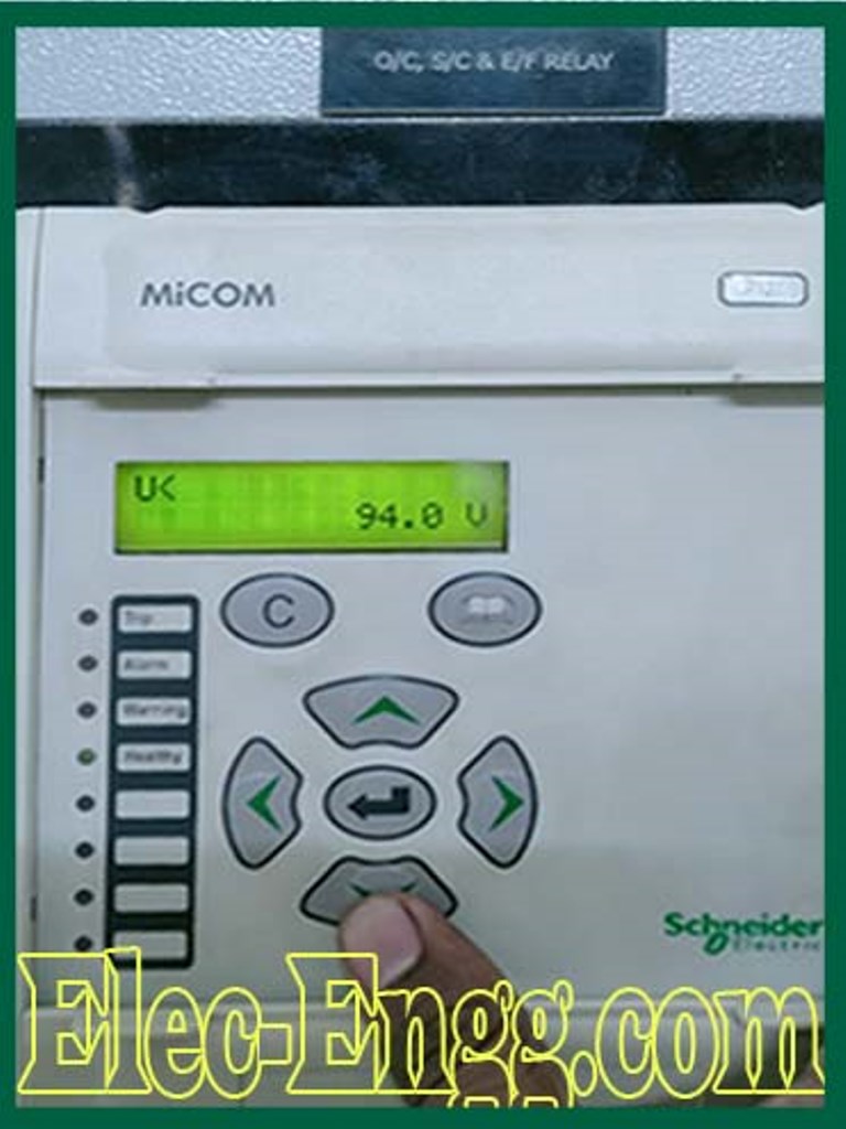
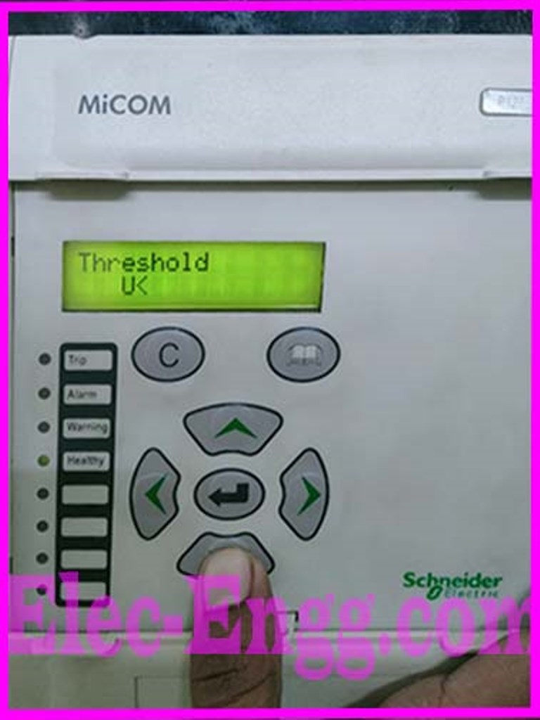
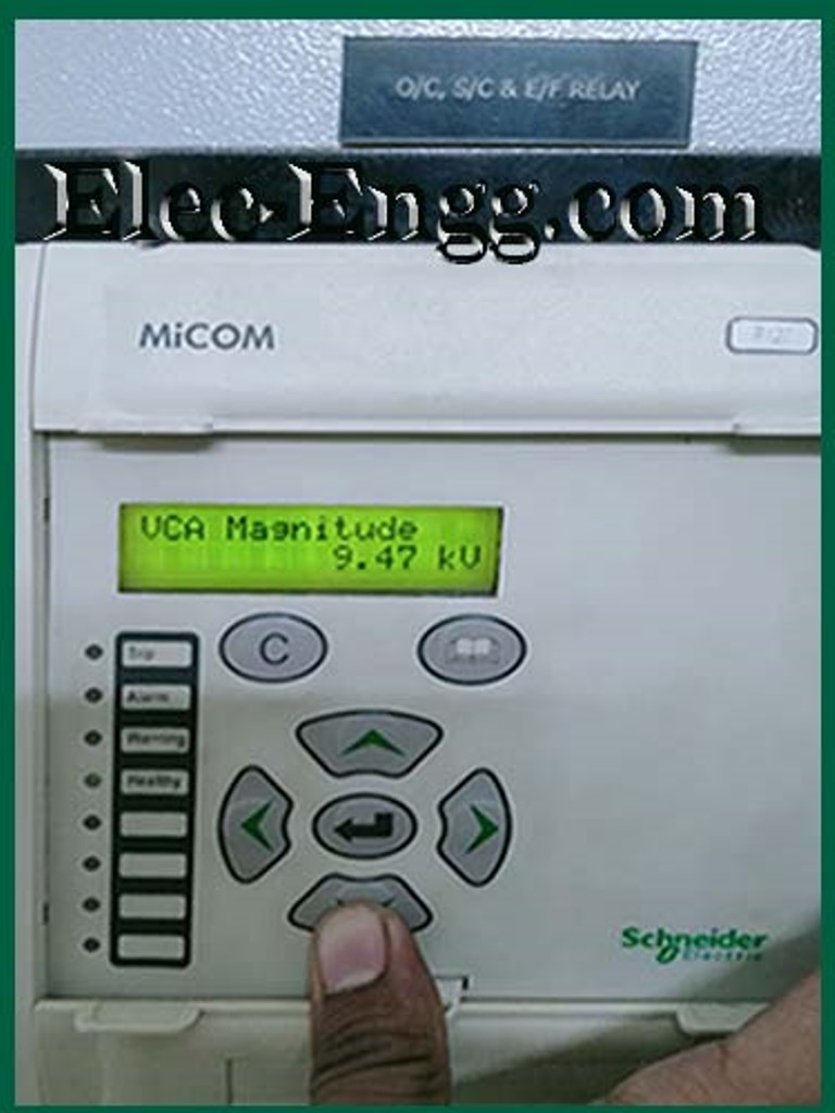
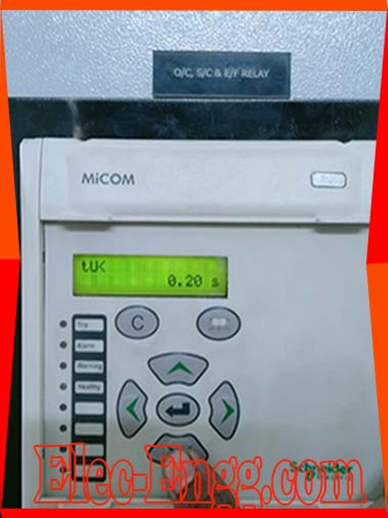
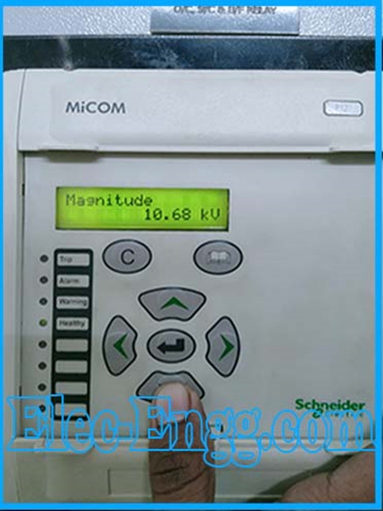
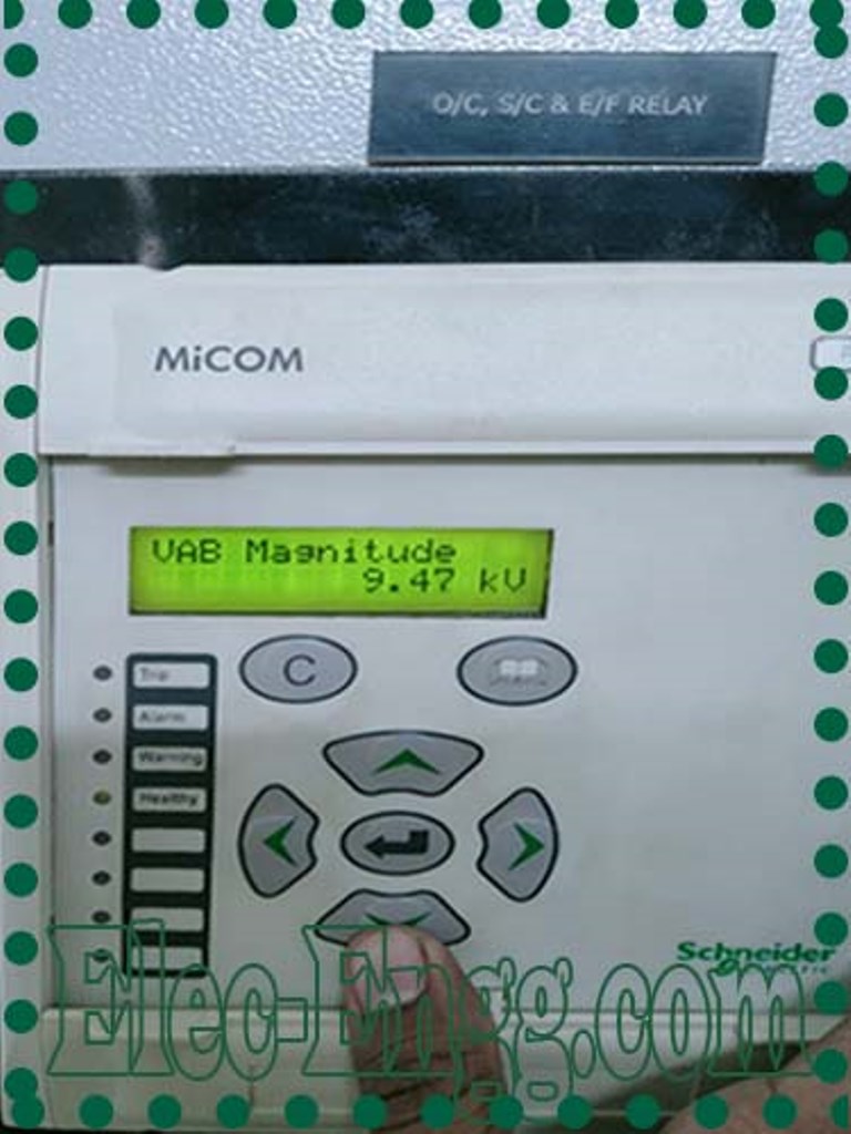
– I have set the under-voltage limit at 9.4kV (94kv, pt ratio 11,000/110, But relay trips at 9.47kV. what to do?
– Make the vt connection vpp+vr. V peak to peak and v residual. In the configuration choose vpp+vr
– can support and provide abb 230kv gis maintenance procedures.
– I need a password for the DILO Sf6 Analyzer kit if someone can help.
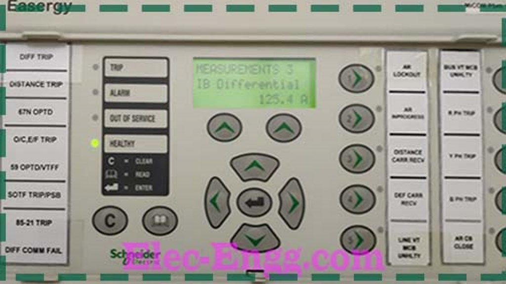
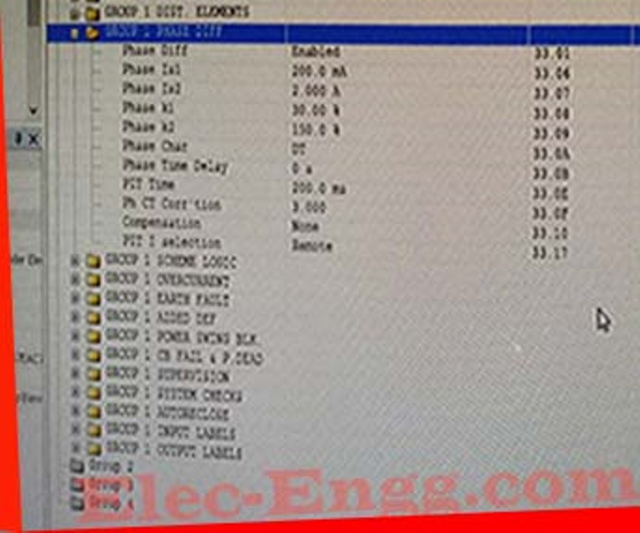
These P546 relays not reading the Remote end current what will be the issue?
– Is communication OK?
– Diff and bias current is reading and no alarm. Now the bay is charged, it’s not possible
– I think no problem because it will make a block for diff and the relay work distance only If there is a problem in configuration, the communication fails May will trip the line.
– What is the CT Ratio?
– 3000/1A bro
– If the load current increases the relay will trip.
– Remote end is 1000/1A. What is the line distance?
– in the p546 relay why are some signals not showing in Siemens sicam pas, pls tell me. But in the data set that signal is there. All signals appear at sicam pas no problem
– The problem is I can’t be able to export icd file, only it’s showing iid, cid
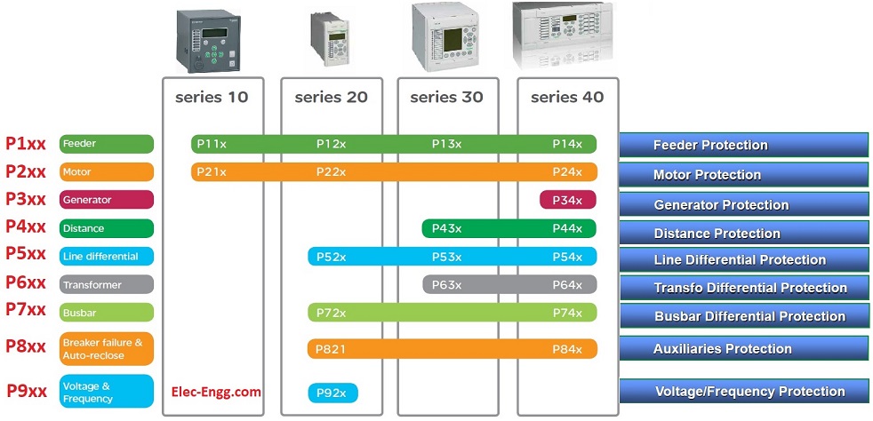
– Need to perform a bit of boosting for this IED. The bit boosting process is a software update program for MiCOM Px20 platforms.
– Contact Schneider certified repair center, team.
– I have two P546 relays, if any trip happens in relay one General trip LED is glowing. But in another relay only particular protection only the Gen trip LED glowing, please let me know what is the issue.
– look in the front panel, menu system data, relay address, which address is set, if 255, try changing it to 1
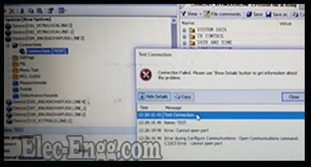
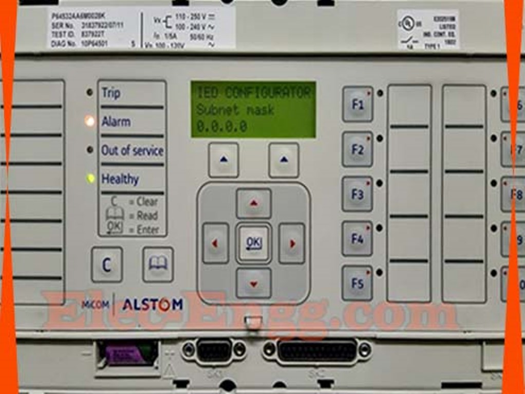
– I have this Relay, I’m trying to change the IP address but I can’t edit it on the relay itself. How to change the IP address?
– This is an old version of Schneider make and firmware version relay.
You need to use IEC 61850 Configurator tool which is inbuilt into Easergy Studio to edit this information and send it via serial port initially to be able to see the IP address in the IED LHMI. I have the SEL serial port cable can I use it?
– better to change the MCL file. Easergy Studio Series Port 9-pin cable and Bafo convert or some other converter.
– I have managed to get the Bafo to convert and I have successfully changed the IP address
– I’m facing an issue with the P546 MCL file reporting with Siemens Scada. Scada engineer tells me that signals not reporting, check the static or dynamic settings. Where can I find this setting? But I add the report and control blocks
– Friends I’m facing an issue with the P546 MCL file reporting with Siemens Scada. Scada engineer tells me that signals not reporting, check the static or dynamic settings.
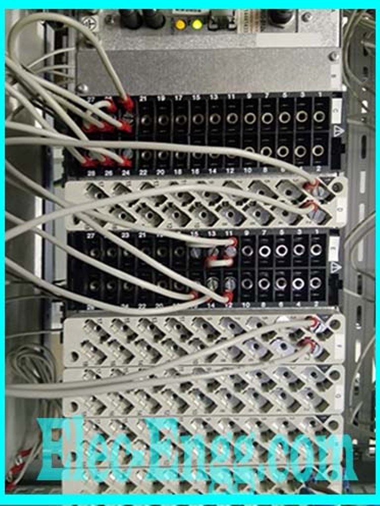
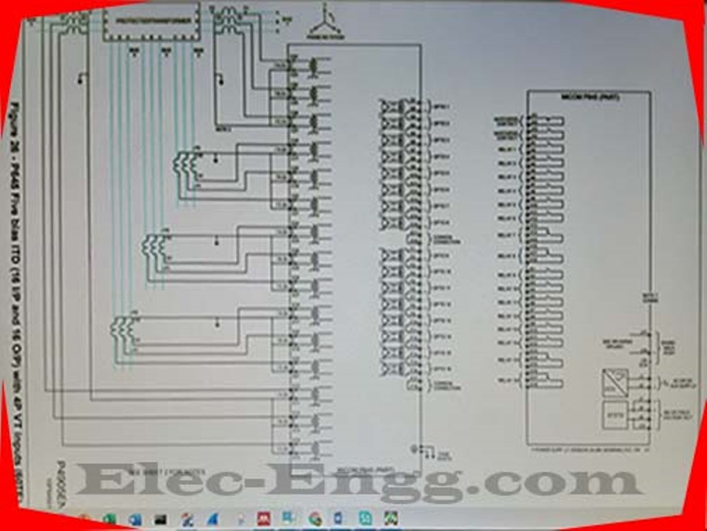
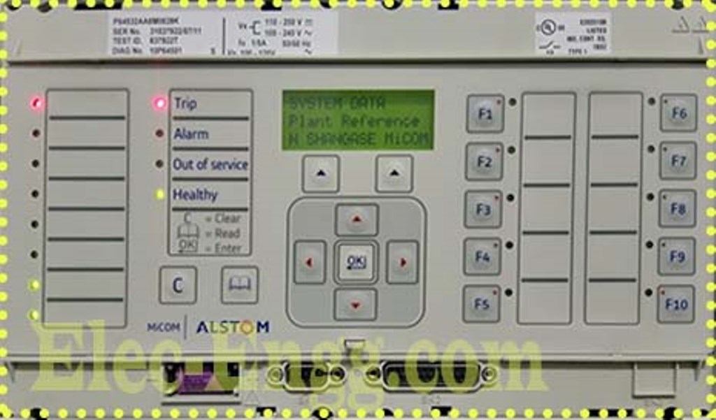
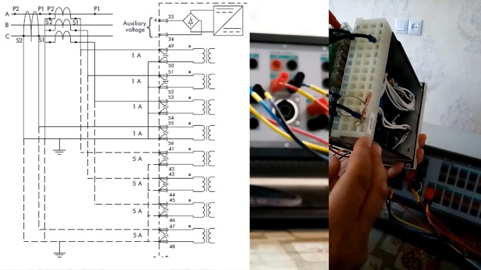
– I have connected the two winding currents of this relay and I can read the right currents on the relay (P645). But now I want to send back the Trip signals to RTDS but I have a problem with the Binary output of this Relay. On the schematics I can’t find out exactly the right binary output, can anyone help me, please?
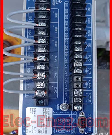
-The back view of the relay and on C and E it’s where I have connected winding currents.
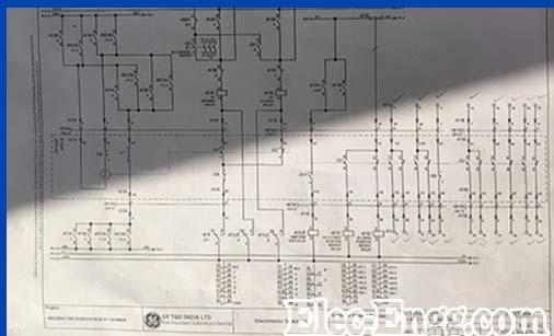
– These are the schematics I got from the manual. The relay serial number is 837922.
– In MICOM always the binary output hardware slot is next to the power supply module. In your case, it is H and G slots for the 16 numbers of outputs in total as per your scheme and actual hardware.
– Thank you, I have done the connection and the relay can send back the Trip signals to RTDS.`
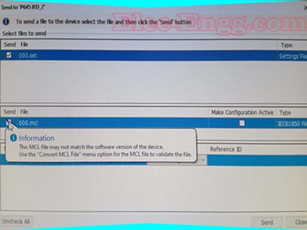
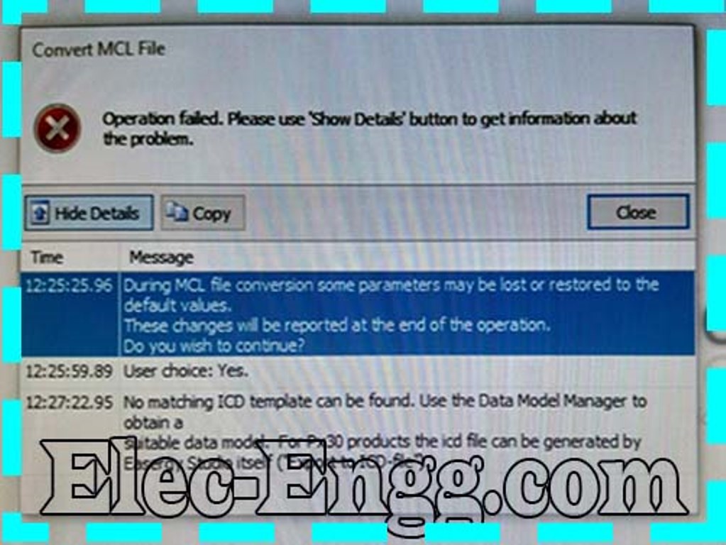
– when I’m sending the MCL file I get these errors, what can be the problem? On this Relay P645.
– You can directly download the data model from the server.
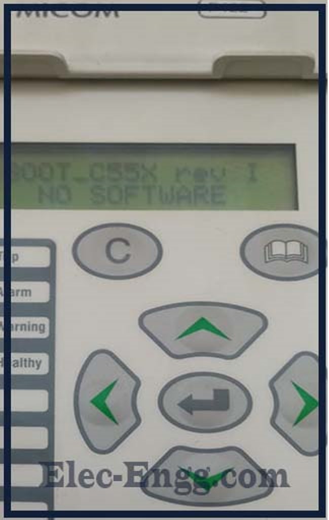
– I have a Micom p443 distance relay & I face a problem when testing it through quick CMC. I didn’t get good reach results for quad (ground fault}.
– this may happen if you did not provide enough auxiliary voltage to the power supply module. I assume the relay was in a Healthy state before the problem in that case is related to the Processor card. Option-1.We need to inform GE (Formally Areva-ALSTOM) that they try to update the firmware via a parallel port using the Px40 download & calibration tool to the healthiness of the IED processor board(chances are very low to make the IED healthy in this method).
Option 2:Isolate the IED if it is part of the energized bay and replace the front HMI case along with the processor board if you have the same model and version spare replay.
Option 3: Contact GE and they will support you with the new healthy processor card loaded with the right.
To join our discussion groups: https://elec-engg.com/whatsapp-group-for-protection-engineers/
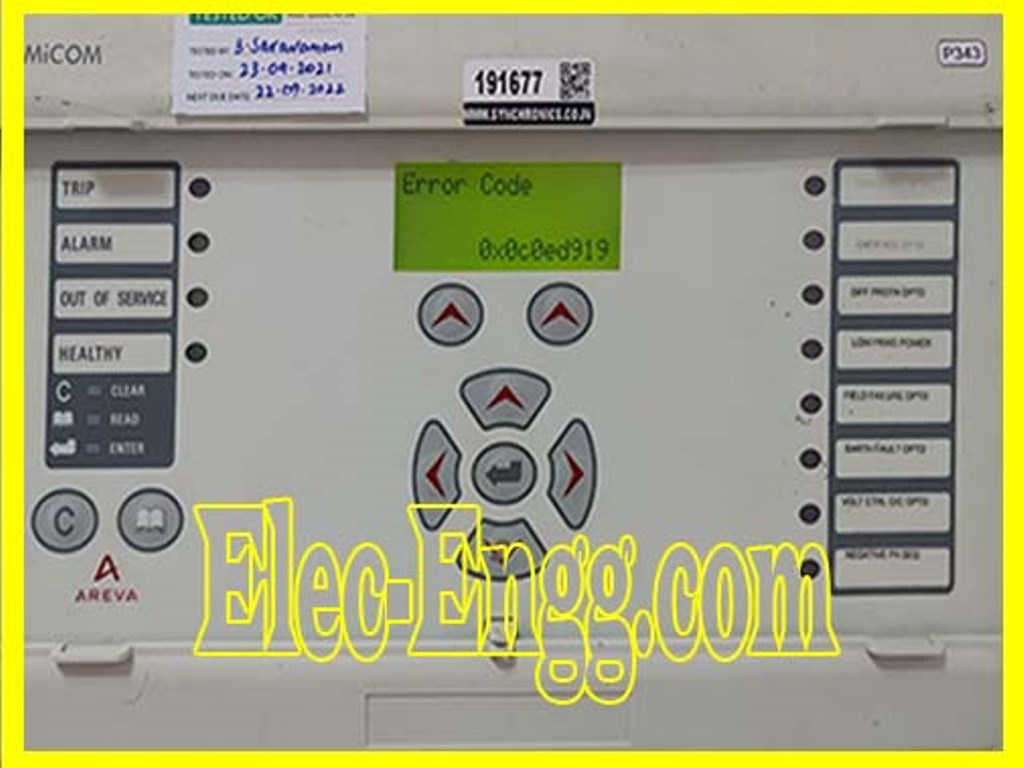
– Can anyone help with this error code? What does it mean?
– you can check this information in the MiCOM relay manual of Troubleshooting->Error Message/Code on the Powe up section.
in your case, it is related to 0x0c0e which means the problem is related to the output modules in the faulty relay. Maybe you can replace from spare relays to make the relay healthy.
– I mean just replace the output modules only from the front side of the relay. this problem is related to the processor card in the front, you need to replace the processor card from the spare relay which is having same model and firmware version in order it makes the relay healthy.
If the relay is within the warranty you can contact Schneider to replace it for free from their side, they will bring the spare processor card and update the firmware from their side/or send you the healthy processor card with the right firmware to the site. You need to install the latest connectivity package for the ieds that belong to the PCM project. You can manage the connectivity package from the update manager.
Check there to see if you have all the required versions installed for different product types.

Elec-Engg.com
For joining our discussion groups: https://elec-engg.com/whatsapp-group-for-protection-engineers/
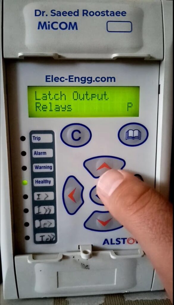
– Can I clear the Tiz error through the software
– Software is not required. You can do it from the front of LHMI using key combinations.
I have an Abb relay rel 650 it cannot autoclose. the relay has CB ready all active and all statuses of the closed and open state.
– Did you check the events and what type of fault type (single-phase and other CB-ready status also interlock input)?
-OK, what type of fault scenario are you creating to check the autorecloser function?
– zone 1
– faulty is in zone 1
– Is it a single-phase fault or are you creating a fault in phase to phase (double/two-phase )or three phases?
– single-phase L1-E
– OK, are you sure the relay is only receiving single-phase fault? Did you check in the DR?
– sir I checked in dr recorder
As u know, Elec-Engg’s main purpose is making video training in the field of substation automation and protection relays
🔻our courses: DIGSI 4 & 5, PSCAD, ETAP, ABB PCM600, IEC61850, Micom, Testing & commissioning, Generator protection, DigSILENT 🔺

Elec-engg.com
– how to test open delta PT input to protection relay?
– Depending on your setting, you can apply voltage and test it.
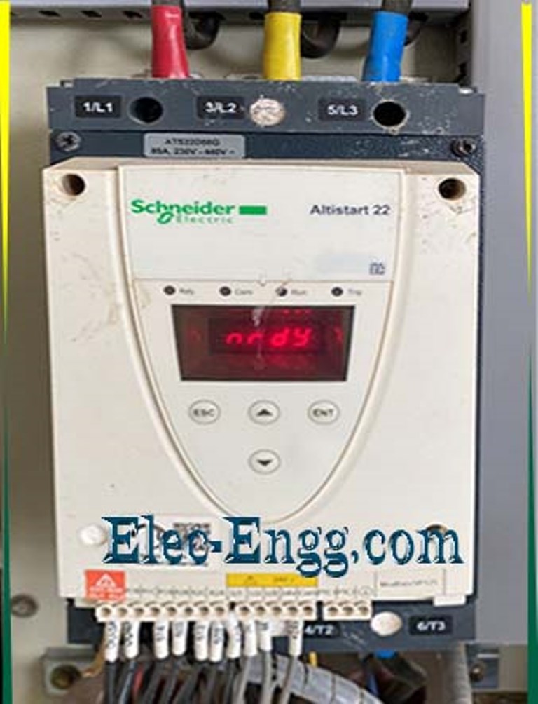
– I have this relay of Schneider P139, we just received it I am trying to energize it from the auxiliary supply but it’s giving an error
– this is the display response when I apply the auxiliary power to switch on the relay. this is my connection where pins 4 and 3 are for DC supply and pins 1 and 2 I short it with the grounding. can anyone guide what can be the reason? why the relay is not turning ON? Is there a connection problem or the problem with the relay itself?
– the power supply is set to 120V from FREJA 300. but when connected to this relay it SUDDENLY drops to 20V
– Relay load is more than Freja power supply. Use a separate power source
– Check whether your model has that feature, Then enable it in configuration.
– Have u checked the correct CB status and AR settings? Do a zone 1 trip and extract the events. Conditions for AR in Schneider
1. Output contact should be assigned for Close Cmd.
- Keep Dead time less than Pole Disc time
- Keep trip mode in Single PH.
- Ensure CB status in 52a or 52b and ensure you have mapped the same for CB Aux A, B, C.
- AR Block should be Zero.

For joining our discussion groups: https://elec-engg.com/whatsapp-group-for-protection-engineers/
– who can help me with the Schneider relay auto-reclose issue? the C264 cannot even accept being connected
– Change the HMI from spare BCU. You need to remove the top and bottom caps first. Use screwdrivers to remove the HMI and change it from a healthy spare BCU.
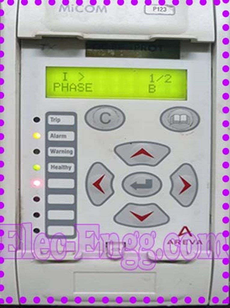
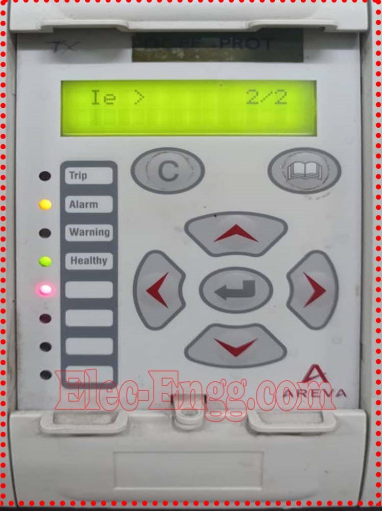
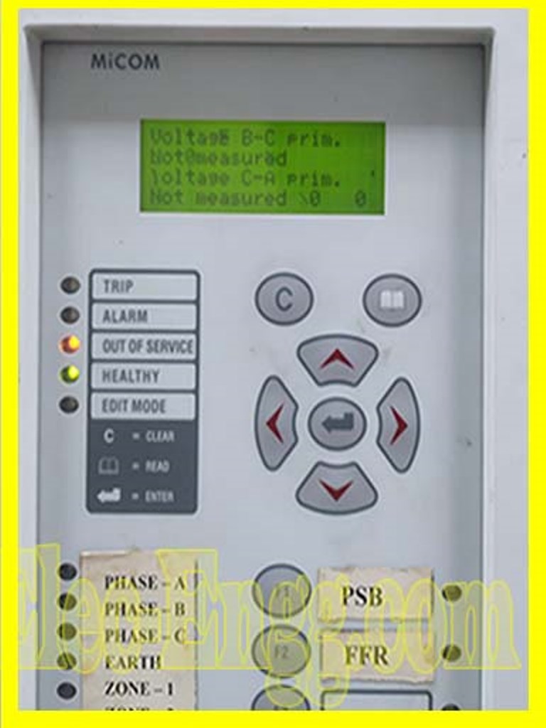
1. Relay is not measuring any amps above 30, it is showing not measured.
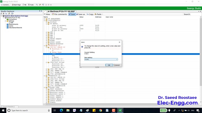
– Need help to configure the same, and also verify the settings. The relay is not displaying any current above 30 A. The relay has been reset to factory defaults. So need your help to configure the relay.
– This is the setting file right
– Drivers of the port were not found on the laptop. Download and install the USB drivers and the issue will be resolved. The name of the driver depends on the RS232 USB converter.
For joining our discussion groups: https://elec-engg.com/whatsapp-group-for-protection-engineers/
– Twido Plc Schneider. We didn’t get to communicate with this plc

– can we have the same settings for different RTUs? Please explain.
– All RTUs will have the same configurations as IEC101 is a protocol, which means a “set of rules to be followed” by everyone to use it.
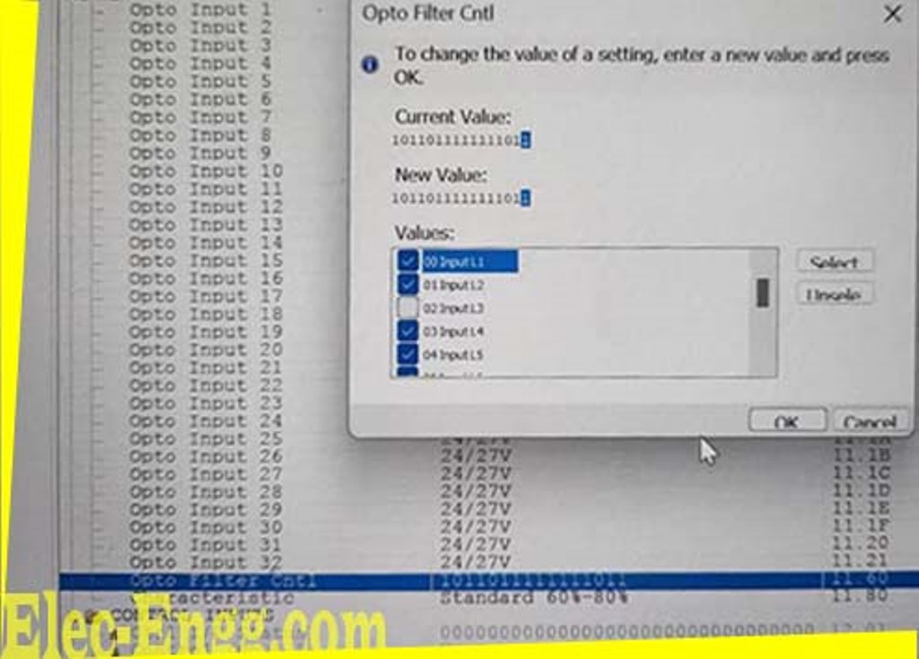
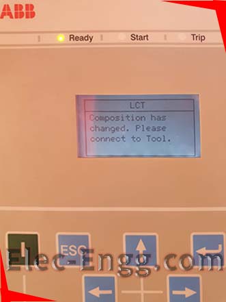
– But I can’t extract the relay settings in remote through agile software. It shows a high-level password is required while extracting settings in agile software
– You can use “OTTER” as a level 1 access password or Try Configurator
– Why do we use a power supply with Interface module IM and digital inputs and output modules at smtic 5 plc?
– This power supply converts from 220 v AC to 5 v DC, that’s why we use this at the control panel Factory report straight line graph

Elec-Engg.com
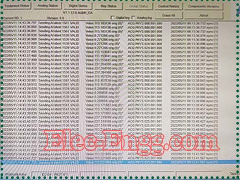
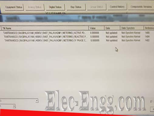
– I have established a connection with the control center but data is communicating due to date and time non-synchronization. data is not communicating* GE Agile GTW software
– In my substation, we were connecting ABB relays (as bank capacitors) to our local network
But every time we connect the fiber cables to ABB relays, The whole network goes down
– Does that relay have an RSTP nic port? RSTP must be enabled with priority settings in all switches. RSTP priority should be configured higher value on IED than other switches in the network
-It is an HSR loop bro, not RSTP
– What is HSR?
– High-availability Seamless Redundancy is a network protocol for Ethernet that provides seamless failover against failure of any single network component.
Google it for more info
For joining our discussion groups: https://elec-engg.com/whatsapp-group-for-protection-engineers/
– How to calculate the zone 2 setting for the radial feeder?
– Check the individual battery voltage. Generally, it is line impedance + 50% of the adjacent shortest line for zone II. Believe your batteries are not getting charged in reality. Please check the advised float & boost charging Volts, what is recommended charging current, and once you complete 1st charge, conduct a discharge test to ensure that the batteries are ready for backup.
– I had one similar case in my 1st project (25 years back), the charging voltage was not correct, and the charging current for the float charge was also found to be set on the lower side.
– This may also be possible with very old electrolytes and storage beyond recommended time by the manufacturer with electrolyte filled in cells and without charge
– Finally, we found 1cell failed, we changed it. now ok.
– During the battery run-down test, we found the size of the cable from the DC panel to the DC motor is not enough (motor current is more than normal current because of high voltage drop).
We doubled the size. From the beginning of the new test, the current value is high and it does not correspond to the voltage value and current value for +1 higher up than+2
-1 higher than -2
+1 129A
+2 149A
-1 129A
-2 149A
What do you think, terminal lug not connected properly?
– One of the most important skills that a relay test engineer must possess is how to administer the test, which means that he must know in advance what test is required of him. What is the number of wires that must be provided? What type of relay should be tested, and how to connect it to the laptop? How to connect to the injection device, and is it possible to use Dry Contact or Wet Contact from the panel as feedback to the injection device?
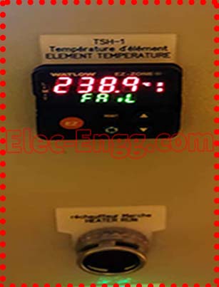
how to increase SP value in the controller? anyone can help us.
– Seems to be connected to be initiated by tripping command from RED615. Works like the initiation of Breaker failure that will depend on CB status or connected via 52a
Kindly assist with Reyroll LMT 6.6-30kV switch gear Factory Acceptance Results or typical test reports.
– Anybody here can help me with the default IP of Alstom CSD RPH3?
Protection user x: How much DC current is a typical tripping coil of 220kV circuit breaker drawn during operation?

– I have to commission transformer 33k. ct in the transformer got fail for ratio accuracy for the HV side But for LV ok, any info can share. I’m using a Ct analyzer Omicron
– did you ground the other transformer bushing which not under test?
– Not if the ct is at yellow phase, Dyn11, do I need to ground also?
– 1s1 and 1s3 Pass but for 1s1 and 1s2 failed
If you are interested in joining the groups, Please save the following number as Ali and text him ” join sharing group ” on WhatsApp: https://elec-engg.com/whatsapp-group-for-protection-engineers/

PROTECTION RELAY SYSTEM IEC 61850
elec-engg.com
– Does anybody have a method statement for battery discharge testing? What are your bank capacity and cell voltage?
– 12V
– Lead Acid battery
Fully charge cell voltage= 2.1
Min discharge cell voltage= 1.8
A 12V battery has 6 cells. Let’s say u have a bank of 600AH of 110V. If U discharges it with the load bank of 4.4kW. The current will be 40 amp and continuous flow up to the battery reaching its discharge point.
Multiply the time (hr) by the 40 (current) and u will get the remaining capacity of the bank.
Make a table accordingly.
– Dear colleagues, our VT 15kv/100v was damaged and secondary cables were under very high temperature by mistake short circuit to the ground.
Now new VT installed and the client requested to change a new cable but actually, the insulation resistance for these cables is still ok nothing special.
– Better to change. VT is very sensitive in case of a ground fault. It can burst/ blast and cause severe damage. Cable worth noting in front of that risk.
– also better not to only consider IR. After dealing with temperature, physical insulation gets harder and its integrity gets weaker. Kindly assist with the best method/ test equipment for online partial discharge testing of power cables.
– Dear colleagues, micom relay has a trip coil supervision function?
– no
For joining our discussion groups: https://elec-engg.com/whatsapp-group-for-protection-engineers/

Elec-Engg.com

