General:
- Check the appearance of the motor; Check for body damage or damage to the cooling fan blade or shaft
- Manually rotate the shaft to check the bearing condition; Check for free & smooth rotation.
- Note the motor data from the motor NAMEPLATE
- Earth Continuity: Use your ohmmeter to verify the resistance between earth and the motor frame is less than 0.5 Ω
- Power supply– correct voltage (230 volts per line), 415 v between Ll to L2, L2 to L3, and, L3 to L1
Three Phase:
- Ensure the terminal for the power supply is in good condition. Check the connection bar for the terminal (U, V, W ). Connection type – STAR OR DELTA

- Confirm the power supply VOLTAGE for the electric motor. 230/400.
- Using the multimeter, check the continuity of winding from phase to phase (U to V, V to W, W to U). Each phase to phase must have continuity if the winding is OK
- Check the motor winding ohms reading using a multimeter or ohmmeter for the phase to phase terminal (U to V, V to W, W to U ). The ohms reading for each winding must be the same (or nearly the same)
- Insulation resistance of motor winding using Insulation tester meter set to the 500 Volt scale (1000v DC). 1. Check from phase to phase (U to V, V to W, W to U) and 2. check from phase to earthing (U to E, V to E, W to E). Minimum test value of the electric motor is 1 Meg Ohm (1 MΩ)
- With the motor running, check the running amps of the motor using a Clamp on the meter. Compare to the FLA on the nameplate of the motor.
- If every step is completed, decide the condition of an electrical motor either OK or NEED TO REPAIR
Single Phase
Check the motor winding ohms reading using a multimeter or ohmmeter. (C to S, C to R, S to R). The reading for starting to run should be equal to C to S + C to R.

Correct electrical terminal identification
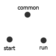
There are three-terminal connections on a hermetically sealed motor compressor and are as follows: Common (C), Start (S), and Run (R). To identify the correct terminal connection the following procedure applies:
- The highest resistance reading is between the start and run terminals
- The middle resistance reading is between the start and common terminals.
- The lowest resistance reading is between the run and common terminals.
