
- #100 @Course Code
- Power System Protection for Beginners
- Course Creation: December 2025
- Instroctor: Dr. Saeed Roostaee
- Total time till now: 3 hours 25minutes
- This course is under recording, please join our WhatsApp group for updates: https://elec-engg.com/updates/
Chaper 1: HV
A: Power Generation and Transmission
- Basic overview of Generation and transmission
- Power System components
- World electricity generation
- Single Line Diagram (SLD)
- Power Generation Technologies
- Hydro-Electric Power
- Hydeo Power Plant in India
- Fossil fuel power
- Coal Power Station in India
- Nuclear power generation
- How does a Thermal power plant work?
- Wind energy
- Solar power
- Power Grid Infrastructure
- Electrical grid
- India National Grid Map (N, NE, S, W, E)
- European-wide synchronous grid
- National Grid
B: Substation and Its Components
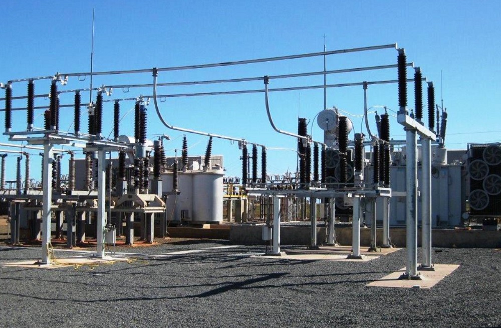
- HV substation in India
- Type Of Substations
- Elements of Substation
- Power Line
- Ground wire
- Wave trap
- Potential transformer
- Disconnect switch
- Earth switch
- Circuit breaker
- Current transformer
- Lightning arrester
- Main transformer
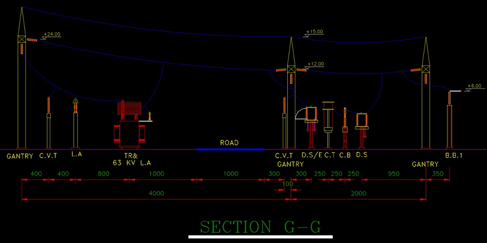
- Substation Layout
- 400/63/20 kV substation layout
- General Single Line Diagram (SLD)
- Protection Single Line Diagram (PSLD)
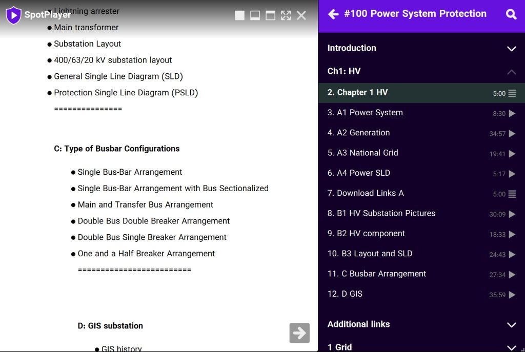
C: Type of Busbar Configurations
- Single Bus-Bar Arrangement
- Single Bus-Bar Arrangement with Bus Sectionalized
- Main and Transfer Bus Arrangement
- Double Bus Double Breaker Arrangement
- Double Bus Single Breaker Arrangement
- One and a Half Breaker Arrangement
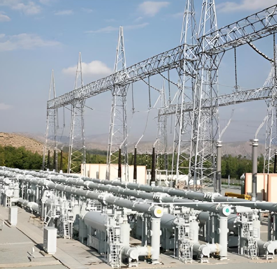
D: GIS substation
- GIS history
- GIS Vs. AIS
- GIS installation
- Maintenance
- GIS elements
E: Instrument transformers
- Why are instrument transformers needed
- Voltage/Potential Transformers (VT/PT)
- Current Transformers (CTs)
- Basic working principle
- Bushing CT
- Free-standing CT
- Pass-through CT
- Window-type CT
- Bar-type CT
- Wound type CT
- High voltage CT
- Tank type CT
- Top-core CT
- CT Ratio
- CT Polarity
- Excitation
- CT circuits
- VT circuits
- Metering Core
- Protection Core
- CT classes
- CT shorting block
Chaper 2: LV
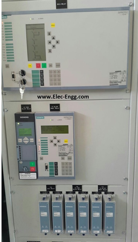
A: Control & Protection Panel
- Introduction to Control Protection & Metering System
- Type of Panels & their usage
- Panel Construction & Components
- Control Panel
- Synch check
- Panel Accessories and Components
- Terminal Blocks
- Metering Components
- Wiring Components
- Control Switches
- Protection Relays
- Automation Components
- Protection Panel
- TCS Relay
- Trip Relay
- Lockout Relay
- Annunciator
- Electromechanical Relays
- Static Relay
- Numeric Relays
- BI/BO, AI/AO, CT/PT, NO/NC, Communication Ports.
B: Schmeatic Diagram
- Introduction to Electrical Drawing
- Typical Electrical Drawing Symbols
- One-Line Diagrams (Single-Line Diagrams)
- Overview of CRP Schematics
- Connected line or wires
- Wattmeter
- Varmeter
- Opened contact
- Closed contact
- Current transformer
- Current transformer with marked polarity
- Ammeter
- Voltmeter
- Thermal relay
- Three-winding three-phase transformer
- Overlap Line or wire
- NO contact
- NC contact
- Coil
- Emergency switch
- Contactor
- Changeover
- Selector Switch
- Push button
- Power factor meter
- Frequency meter
- Therma OL relay
- Timer
- Terminal
- Auxilary contactor
- Panel and Equipment Layout
C: Protection Classification, Types & ANSI Codes
- Common Acronyms
- ANSI Standard Device Numbers
- 21 Distance Relay
- 21G Ground Distance
- 21P Phase Distance
- 24 Volts-per-Hertz Relay / Overfluxing
- 25 Synchronizing or Synchronism-Check Device
- 27 Undervoltage Relay
- 27P Phase Undervoltage
- 32R Reverse Power
- 46 Reverse-Phase or Phase Balance Current Relay or Stator Current Unbalance
- 49 Machine or Transformer Thermal Relay
- Thermal Overload 50 Instantaneous Overcurrent Relay
- 50BF Breaker Failure 50N Neutral Instantaneous
- Overcurrent 51 Time Overcurrent Relay
- 51N Neutral Time Overcurrent
- 51V Voltage-Resistant Time Overcurrent
- 59 Overvoltage Relay
- 67 Directional Overcurrent Relay
- 67N Neutral Directional Overcurrent
- 79 Ac Reclosing Relay / Auto Reclose
- 81O Over Frequency
- 81U Under Frequency
- 86 Locking-Out Relay
- 87 Differential Protective Relay
- 87B Bus Differential
- 87G Generator Differential
- 87GT Generator/Transformer Differential
- 87L Line Current Differential
- 87RGF Restricted Ground Fault
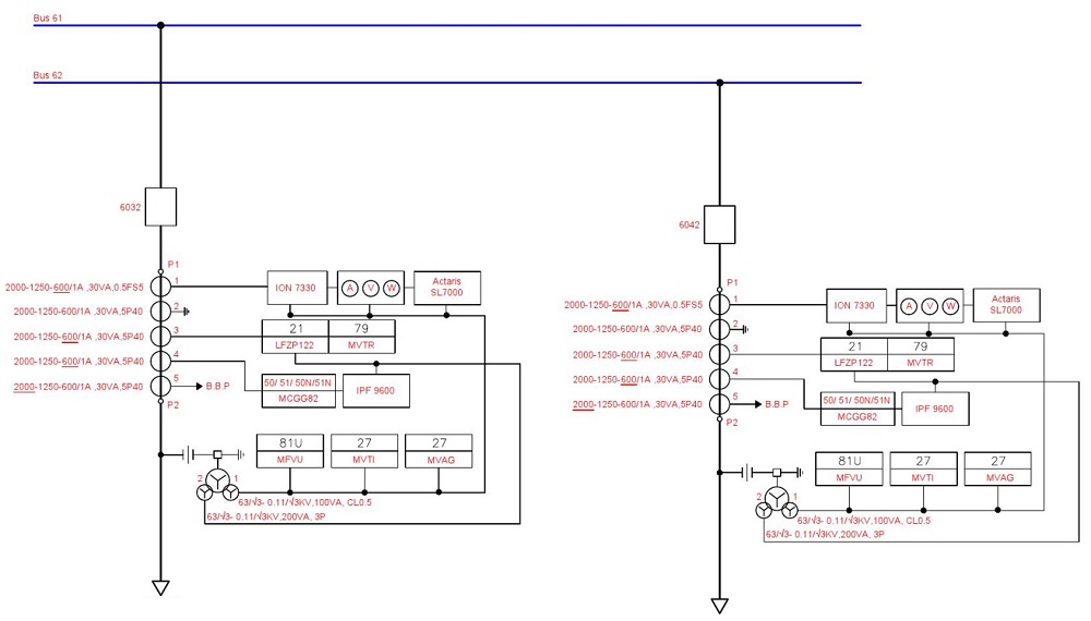
D: PSLD (Protection Single Line Diagrams)
- Transformer protection single line diagram
- Line protection single line diagram
- Busbar protection single line diagram
- Feeder protection single line diagram
Chaper3: Faults
A: Faults
- Normal Operation of Power System
- Abnormal Condition of Power System
- What is the fault
- Abnormalities
- Types of faults
- Faults in Windings
- Symmetrical fault
- Unsymmetrical faults
- Fault statistics
- Transmission Line Faults
- Earth Fault on H.V. External Connections
- Phase-to-Phase Fault on H.V. External Connections, Internal Earth Fault on H.V. Windings
- Internal Phase-to-Phase Fault on H.V. Windings Short Circuit Between Turns H.V. Windings
- Earth Fault on L.V. External Connections
- Phase-to-Phase Fault on L.V. External Connections, Internal Earth Fault on L.V. Windings
- Internal Phase-to-Phase Fault on L.V. Windings Short Circuit Between Turns L.V. Windings
- Faults in Generators
- Generator Stator Earth Fault
- Generator internal faults
- Faults due to the load
- Overload
- Unbalance Load
- Loss of field
B: Fault Simulation and Studies
- Fault calculations
- Symmetrical Components
- ETAP
- DIgSILENT PowerFactory
- PSCAD
- Single-phase fault simulation
- Three-phase fault simulation
- Earth fault simulation
C: Criteria for fault detection
- Overcurrent I>
- Earth-current IE>
- Current unbalance (negative sequence current I2>)
- Undervoltage U<
- Overvoltage U>
- Over- and Under-frequency
- Leakage (Differential) current
- Underimpedance Z<
Chapter 4: Protection
A: Protection Introduction
- Importance of the Protection System
- What do we want to protect?
- Function of protection systems
- Requirements for system protection
- Elements of a Protection System
- Primary Protection
- Backup Protection
- Zones of Protection
- Primary and Backup Protection
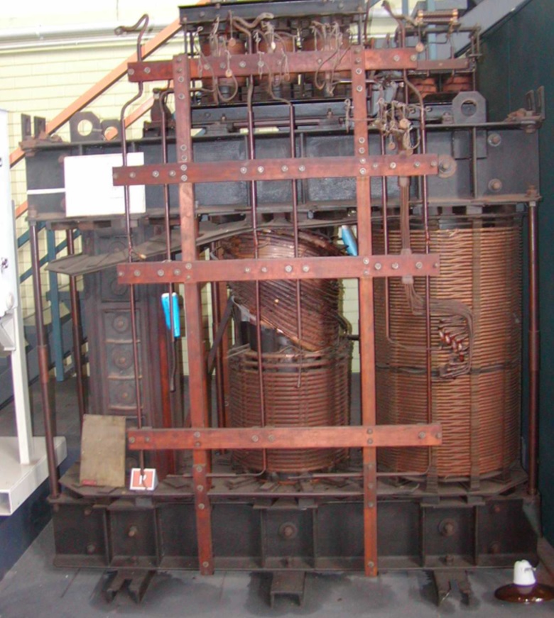
- Protection Relay History
- Electromechanical Relay
- Static Relays
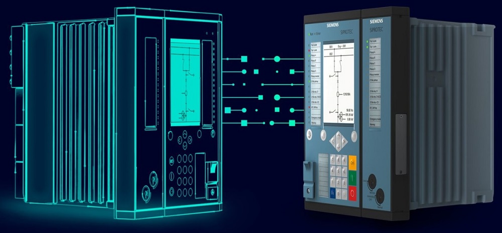
- Numerical Relays
B: Numerical Relays
- Numerical Relays
- Advantages of Numerical Relays
- Structure of Numerical Relays
- How do Numerical Relays work?
- Analog to Digital Conversion
- Digital Phasor Measurement
- Example Feeder protection
- Numerical Relay Manufacturers
C: Relay Selection Guide
- Available Device Types
- Fields of Application
- Medium-Voltage Application
- Transformer Protection
- Generator Protection
- Line Protection
- Busbar Protection
Chapter 5: SIPROTEC 5 Online Mode
A: Online Mode
- Relay Offline Vs. Online Mode
- Device Information
- Config Information
- Process Mode
- Commissioning Mode
- Simulation Mode
- Edit device time
- Copy the online device to the project
- Assign an online device to the project
- Change the assigned device
- Create a backup from a device
- Load the Configuration to the device
- Retrieve Device Data
B: SIPROTEC 5 Web UI
- Device Information
- Relay Hardware and order code
- Set the relay date and time in the web UI
- Monitor Relay Displays
- Monitor binary inputs
- Monitor Binary outputs
- Monitor LEDs
- Access to all LOGs and download LOGs
- Runtime Data
- Monitor the recorded fault in the web UI
- Manual Recording trigger
- Download relay fault records
- Measurements
- Check the relay setting values
- Change settings
- Apply settings
C: Relay measurements
- Operational measured values
- Fundamental Components
- Symmetrical Components
- Function-specific measured values
- Energy metered values
- Statistical values
- Primary values
- Secondary values
- Snapshot
- Inject the three-phase values into the relay and monitor the relay measurements
D: Logs and Indications
- Reading Indications from the PC
- Operational Log
- Fault Log
- Ground-Fault Log
- User-defined Logs
- Config Logs in the matrix
- Download Logs
- Time stamp
- Relative time
- Entry Number
- Function Structure
- Signal name
- Signal Value
- Signal Quality
E: Fault Recorder
- Fault Recorder Function
- Fault recording with Pickup
- Fault recording with Pickup & AR cycle
- Storage settings
- Pre-fault time parameter
- Post-fault time parameter
- Sampling Frequency
- Fault recorder config
- Download fault records
- Comtrade format
- COMTRADE Viewer
- Time signals
- Harmonic signals
- Binary signals
- RMS and Instantaneous values
Chapter 6: OC Protection Functions
A: Overcurrent 50/51
- SIPROTEC 5 Over current config
- Overcurrent DT element (ANSI 50)
- Overcurrent IT element (ANSI 51)
- Threshold parameter
- Operate the delay parameter
- Overcurrent curves
- Method of measurement
- Time dial parameter
- OC logic in SIPROTEC 5
- Block OC
B: Overcurrent Earth 50N/51N
- Introduction to the Earth fault protection function
- IE calculation
- IE measurements
- Config earth fault protection
- Logic Diagram
- Threshold
- Operate delay
C: Directional Overcurrent 67
- Why Directional overcurrent protection
- How to configure Directional overcurrent protection ANSI 67 in SIPROTEC 5
- Voltage Connection
- Forward direction
- Reverse direction
- Blk. by meas.-volt. failure
D: Directional Overcurrent Earth 67N
- How does 67N work?
- How to configure 67N?
- IN measured
- 3I0 calculated
- Forward direction
- Reverse direction
Supplementary files:
We’ve gathered a library of helpful resources (PDFs, diagrams, videos, and more) for this course and attached them as free resources to support your study.
Course Updates:
- We continually update our courses to improve your learning experience. Please share your feedback, comments, questions, or suggestions—we’ll consider them for the next updates.
- Join our WhatsApp group to stay informed about the latest updates and new courses.
Hi sir :
1-when this course recording will be finished
2-how long the the time of the whole course
3- is this course price will fixed or it may change
Hello Mr. Meam Awad Jasim,
Thanks for your message,
1) within a week
2) Long time access to the course
3) Not fixed, we usually increase our prices to respect our earlier users.