The Australian Protection Symposium is a forum for discussion and sharing of knowledge and first-hand experiences from Australia and around the world, whether it fundamentals, new approaches, technology developments and standards, strategies and implementation experiences, or even failure case studies, there will be a discussion that will benefit you and your organization in the area of protection, automation, and control.
Fundamental Principles and Requirements of Protection Systems
The purpose of this paper is to provide as clear a statement as possible of the functionality that Power System Protection has to fulfill to be considered ‘fit for purpose, and the requirements that this places on the concepts, design, components, and circuitry of protection systems. The statement of functionality is made in such a way as to form the basis of concepts and designs irrespective of the particular technology or combination of technologies used for its delivery. The Electrical Protection of power systems is an essential and critical function. The level of dependability and security required is the highest of any of the secondary circuit functions used in substations. The requirements are stated in a way that is independent of the technology used, to avoid restricting the development of new technology or applications. This approach is in the spirit of IEC 61850 in providing base rules and a framework for developing solutions without restricting the development of new solutions and improved functionality. The content includes key objectives of protection, basic principles applying to any scheme, all of the components involved (not just the relays), primary and backup principles (Remote BU and Local BU), and their implications. It deals with the requirements of secondary isolations of individual schemes required to permit safe work on a scheme while the remainder of the substation is in service, and with the requirements for simulated functional proving of protection schemes, again in a live substation. Segregation principles are also covered.
There are two aspects to the functional requirements:
- (a) The requirements that the protection has to fulfill to perform its functions of protecting the power system and people,
- (b) The requirements that the protection system places on whatever technology or a mix of technologies is used in the delivery of these functions.
Protection is a specialized discipline and requires people qualified or appropriately trained and competent in the discipline to carry out the various protection functions such as protection planning, system analysis, design and specification of relay systems, circuit design, relay settings, testing, installation, and commissioning.
Calculation of Loadability Limits of Modern Numerical Relays
Conventional calculation of load-ability limits of distance relays for different characteristics, such as Mho and Lenz, is based on determining the minimum permissible load impedance which is equivalent to maximum load current so that it does not encroach on the last forward zone reach of distance relay with a safety factor. In this paper it is shown that this philosophy, which is still used in some utilities for the calculation of relay load limit (RLL), does not apply to modern numerical relays due to utilizing the following elements for EHV transmission lines:
- a) load encroachment element (LE)
- b) power swing blocking (PSB).
The functionality of LE is to block the relay under normal loading conditions as long as the load impedance is within the LE characteristic. Its characteristic consists of a circle cut by straight lines which represents the load angle. The radius of the circle represents the magnitude of minimum load impedance. Bearing in mind that LE responds only to balancing positive current, it is shown that LE characteristic does not need to grade with any forward zones as long as the maximum load angle is less than the line angle with sufficient margin.
The main objective of PSB is to block the operation of phase distance elements for stable swing. Its characteristic consists of two blinders or circles, one inner and one outer. The inner blinder/circle should encompass the outermost zone of phase distance protection that has been selected for blocking. The outer blinder/circle should be set so that the closest minimum load impedance locus is outside the outer blinder/circle characteristic for all loading conditions.
In this paper, it is shown that the load-ability limit of distance relays of numerical relays should be calculated based on the outer blinder/circle characteristics of PSB rather than the conventional method of the last forward zone, otherwise the functionality of PSB will be ineffective and relay may trip on stable swings. With this concept mathematical equations for the calculation of RLL are developed for two cases, one with a blinder and one with circular characteristics for PSB. In addition to impedance relays, a methodology for the calculation of RLL for current differential and overcurrent protection of new numerical relays is given. Finally, the results of an analysis of system disturbances that have occurred under normal system loading conditions due to wrong relay settings, design errors, relay failures, and human errors during testing are discussed. It will be shown how these disturbances could have been prevented if the correct design philosophy and test procedures had been implemented.
Download full papers at the end of this page
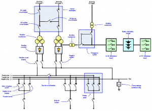
An Overview of D.C Traction Protection Systems
DC electrical traction systems consist of fixed components that enable power to be supplied to trains and trams for their traction and auxiliary operations. The purpose of the system is to supply electric power to rolling stock for traction and auxiliaries. It may also accept power back to the network when regenerated through breaking by the train or tram. The electrical interface is the interaction of the traction supply with vehicle-based systems and components. Key factors that influence the effect on the DC protection system are:
- · Magnitude of electrical load – stationary and moving including the type of train, the current required for powering, the current required for auxiliaries, the number of trains operating, the timetable, and the speed of operation.
- · Traction system capacity including fault levels, protection types, and rate of rising of current.
This paper describes the DC protection system on the traction substation and the limitations and implications of the traction system.
The Digital Substation – Principles, Functions, and Benefits
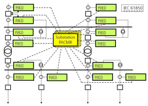
The IEC 61850 standard for Communication Networks and Systems for Utility Automation allows utilities to consider new designs for substations applicable for both new substations and refurbishments. The levels of functional integration and flexibility of communications-based solutions bring significant advantages in costs in all stages of a project. This integration affects not only the design of the substation but almost every component and/or system in it such as protection, monitoring, and control by replacing the hardwired interfaces with communication links. Furthermore, the design of the high voltage installations can be reconsidered regarding the number and the location of switchgear components necessary to perform the primary function of a substation in a high voltage network. The use of highspeed
peer-to-peer communications using Generic Substation Event (GSE) messages and sampled values from non-conventional or conventional sensors allows the development of distributed applications. In addition, the use of optical local area networks leads in the direction of copper-less substations.
The paper focuses on the definitions of the digital substation communication busses such as the station bus for the communication at the station level and between bays as well as the process bus for the communication between the high voltage process and components interacting with it. It analyses the substation communications architectures in substations with full implementation of IEC 61850, i.e. with station and process bus.
The different types of devices required for digital substations are described. Merging units that provide the interface between the current and voltage sensors and the intelligent electronic devices at the equipment, bay, or substation level are described, as well as the distribution of signal and data processing functions between the different devices for both architectures, which are analyzed. Some specific substation applications based on GOOSE and Sampled Analogue Values are described later in the paper and demonstrate the advantages of the new technology. Improvements in functionality, combined with practical elimination of performance or safety issues are covered in the paper.
Download full papers at the end of this page
Impact of IEC61850 ed2 on Protection GOOSE
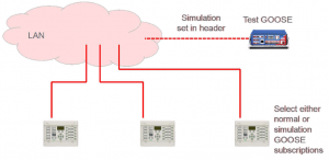
GOOSE itself brings many benefits that can be utilized for various protection signals, however, isolation and testing are critical considerations that are often seen as deficiencies in edition 1 (ed1) of the IEC61850 standard. A key driver for edition 2 (ed2) was to overcome these limitations. This paper looks at various isolation and test methods used for edition 1 and compares them to using edition 2. A major drawback of edition 1 was the inability to use online simulation. This limitation was not obvious and care is needed to ensure simulated or test messages are not used on a live system. This paper looks at the new simulation modes available in edition 2 which greatly improves this situation. The edition 2 simulation mode is quite powerful and this paper also looks at how this functionality can be used in a practical application. One of the stated objectives of edition 2 is to create solutions that can incorporate edition 1 relays. This paper also looks at the practicality of doing this.
Download full papers at the end of this page
Case Study: Implementation of IEC61850 in Generator and Transformer Protection System in NSW Power Stations
Reliability, Efficiency, and Safety are the key objectives of any modern power system, and these can be achieved by the implementation of fully automated systems. The IEC61850 standard has revolutionized the automation process by standardizing system specifications, configuration language, naming convention, communication protocol, and conformance testing. The use of IEC61850 compliant devices can simplify the engineering design process, increase flexibility, and reduce engineering costs. To operate and maintain IEC61850-based systems, plant engineers must acquire knowledge about communication protocols, computer networks, classes, objects, etc. In New South Wales (NSW), the protection systems of the large turbo-generators (660MW units and above) and associated generator transformers have reached the end of their operating life. Most NSW generating companies have already implemented a program for replacing these generator and generator transformer protection systems. The new protection systems used IEC61850 compliant protection relays with an optical, peer-to-peer communication messaging system known as “GOOSE”. Being a protection retrofitting project to existing generating units, there were some difficult choices and design considerations in selecting the levels of IEC61850 implementation to these new protection systems. This paper looks at the extent of IEC61850 implementation in these retrofitted generator and generator transformer protection systems in NSW. It also provides a discussion on the impacts of the IEC61850 system on the operation and maintenance of these protection systems and possible future improvements.
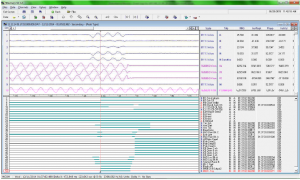
COMTRADE Analysis to Visualize Protection Operations
This paper discusses methods of analyzing waveform recordings from numerical relays to diagnose power system events and confirm relay operations. COMTRADE format recordings often only capture the physical analog and digital signals wired to the relay, while internal protection functions will use algorithms to manipulate these signals before determining a trip condition. With a basic understanding of the relay algorithms, the operating quantity can be derived from the recording and compared to an operating characteristic to verify settings and confirm relay operations.
Examples presented include analysis of harmonic content of inrush waveforms, trip locus of differential and impedance-based characteristics, high impedance-based protection trips, and fault finding installation and application issues.
Download full papers at the end of this page
Verification of Distance Protection Scheme of double circuit transmission line using power disturbance records
The Channel Island Power Station is the major generation source for the Darwin-Katherine region. Power delivery to the greater Darwin region is via two 132kV overhead lines to Hudson Creek Substation which are installed on separate towers sharing a common corridor. Figure 1 below is a simplified network diagram used in the model to study the impacts of the influencing factors including source impedance ratio, load-flow, mutual coupling, fault impedance, single-pole tripping, auto reclosing, and current reversal. The first part of this paper describes the selection of the proposed replacement system. The second part describes the evaluation of the combined effects of the influencing factors and the last part describes verification using available power system disturbance records and the test scenarios generated by RelaySimTest.
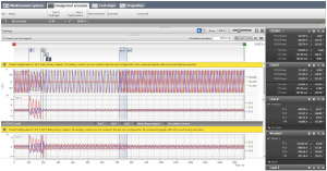
RelaySim Test Scenarios for verification of the protection
Cygnus Atratus, and How it Causes Problems
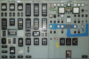
Protection systems deal with two different types of faults, ones we expect and faults that are unique and had not been considered. This paper describes black swan events, and how we as protection people should make our system black swan tolerant. It looks at several events, not all within the power industry, and describes how different thinking may have prevented incidents from occurring. It describes the effect of outliers on fault analysis and black swan recognition. The author has been involved in a black swan style theory for many years. As a book by Nassim Nicholas Taleb has created the terms used nowadays, those terms are used throughout this paper.
Download full papers at the end of this page
Application of the Line Differential Protection Scheme for Radial Transmission Lines
Modern communication networks have dramatically increased the implementation of the line differential scheme as one or both primary protection for transmission lines. The transmission network usually meshes which also provides fault current contribution from both ends of the line. Considering the ongoing need to reduce CAPEX investment, it is expected that the supply to specific loads, for instance, mining in rural zones of Australia, the transmission network could be expanded radially with single or double circuit applications. In a radial system, in the event of a fault, fault current contribution is drawn mainly from the source side. This scenario could potentially create issues with the operation of supervisory elements of the line differential relay at the remote end. This paper reviews this specific application with particular attention to solutions that balance the need for security, speed, and dependability of the line differential protection scheme.

Modeling and Testing of High Impedance Differential Scheme Using Numerical Relays
A high impedance (HiZ) differential protection scheme has been used for busbar protection over many decades. The basic idea used in this scheme avoids problems related to CT saturation through faults by connecting high impedance in series with the operating relay. Relay with high impedance burden and CT’s are connected in parallel to force the false differential currents (caused by CT saturation) to go through the saturated CT’s rather than through the relay. As long as the voltage across the summation point required to operate the relay is higher (with a certain margin) than the
maximum voltage developed during maximum through fault, the scheme provides adequate security. This requirement is usually easy to satisfy and very few utilities ever had an issue with scheme security caused by CT saturation. On the other hand, tripping for internal faults relies on CTs’ ability to provide enough secondary current through a very high impedance of the relay branch during an internal fault. Under an internal fault condition, at least one CT with primary current drives secondary current into high resistance of the relay branch. This creates a high voltage across CT terminals. This voltage usually exceeds the knee point voltage of the CT and eventually saturates (from the second terminal side) other CTs connected into a high impedance scheme. The low impedance of saturated CTs reduces the burden on source CTs but also allows spill current to flow into saturated CT’s not into the relay. As a consequence, in steady-state, the current through the relay flows only during short periods when the voltage across the summation point is below the knee point voltage of CT with the lowest knee point voltage – i.e. periods before the smallest CT saturates. Early schemes had been implemented using high (usually nonlinear) impedance voltage relays. These relays were extremely fast because the very sensitive operating coil in these relays (usually 5mA – 10mA) would operate almost instantaneously when voltage increases over the knee point of internal nonlinear resistors used to set the voltage pickup. Over time, the voltage relays had been replaced with electromechanical (EM) instantaneous overcurrent relays (usually armature type) and burden resistors. More recently, EM relays have been replaced with solid-state and numerical overcurrent relays. The general understanding is that the HiZ scheme performance is expected to remain satisfactory as long as few original design “rules of thumb” are met. At the same time requirements for smaller CT have been intensified due to switchgear size reduction. This paper presents methods and findings of modeling and simulation of an HiZ differential scheme. Relay performance under internal fault conditions was studied. Conclusions and some recommendations for scheme improvements based on these findings are presented.
Download full papers at the end of this page
New Design of Distance Protection for Smart Grid Applications
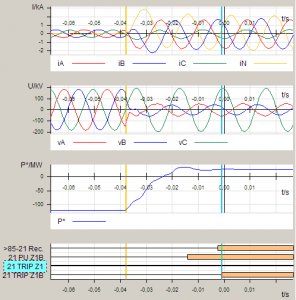
Smart grids of the future will have new challenging requirements for the protection elements regarding selectivity and dependability. The load flow will be increasing, the magnitude and direction of load flow may frequently be changing, and even the network topology will be more complex than today. This paper presents a new design of distance protection that perfectly fits the requirements of the smart grid of the future.
The impedance measurement is based on the calculation of the load compensated fault reactance X and from the line, resistance separated fault resistance. This method is applied for the phase to the ground as well as phase-to-phase faults. Separation of the fault resistance improves the accuracy of the impedance calculation. The method reduces the negative influence of fault resistance during high load flow and minimizes the risk of the wrong pickup during high load conditions. Once a fault is detected, it is very crucial to select the faulted loop to calculate the impedance to the fault. For complicated faults in the complex network of a smart grid, this can be a challenging task with a certain risk of non-selective fault clearance. In the past, the loop selection was done by a so-called decision tree, in which several criteria were applied sequentially to find the faulted loop. Thereby, only the result from one criterion selects the faulted loop. The new approach is different. Several criteria are based on magnitudes of voltages and currents, changes in voltages and currents, symmetrical components, or impedances are applied in parallel. The results of every single criterion are weighted and combined to get a final result for the selection of the faulted loop. With this principle, the efficiency of the loop selection has been optimized to different network topologies by changing the weights of each criterion. The same principle is applied to the directional element. Multiple criteria based on actual voltages, memorized voltages, symmetrical components, or delta quantities are applied in parallel. The final result is obtained as a weighted combination of the result of every single criterion.
Communication Aided Protection Schemes and their Implementation and Testing with State-of-the-Art Technologies
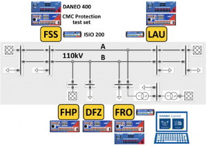
Electrical power systems and the related protection and control systems evolve. Systems get extended, and the existing parts have to be adapted to the new configuration. While extending the primary system is more straightforward in most cases, the adaption of the protection system can be more challenging if the topology of the primary system is essentially changed. The adaption of protection settings is not sufficient to cope with such situations. New protection concepts or improved information exchange between protection relays may be required. This paper describes an electrical power system with five terminals that evolved and how recent technologies were applied for upgrading the protection system and how the testing of the system was performed.
Download full papers at the end of this page
Implementation of Multi-Intertripping Protection Schemes in a Complex EHV Industrial Substation
This paper describes the design, installation, and commissioning of new numerical protection and control and inter-tripping schemes at an EHV substation. The substation supplies a critical and large industrial plant (paper mill). The connection consists of two radial 110 kV transmission lines connecting four 25 MVA, 110/6.6 kV transformers, two of which are dual wounds. Each transmission line is directly connected to a transformer. The 6.6 kV sides of the transformers are connected to different busbars via circuit breakers. For a fault on the 110 kV lines or the transformers, the remote end 110 kV circuit breaker and appropriate 6.6 kV circuit breakers must open.
This arrangement required complex inter-tripping schemes between the protection devices of the transformers within the substation and between the protection of the local substation and remote substations. The secondary work at the local and remote EHV substation included installing new 110 kV transmission line protection schemes, consisting of Main ‘A’ and Main ‘B’ new numerical relays for each line. This included the removal of existing inter-tripping schemes.
The project necessitated an innovative design, settings, and logic programming to be implemented on new relays. Existing secondary infrastructure including copper cables and intra-substation fibers of the single old protection scheme was utilized for the now duplicated transmission line protection. This involved the following.
- Removal of the existing multi-inter tripping schemes and reconfiguration using a new numerical protection scheme with appropriate setting and logic programming.
- Utilizing fiber optic cable and digital transceivers/receivers for provision of trip/close circuits.
- Implementing a reliable design and setting based on sound standard policy/philosophy.
- Installing, testing, and commissioning the new protection and inter-tripping schemes with minimum plant outages due to load critically.
Finally, the paper discusses how the implementation of the project involved innovative solutions so that new primary equipment and secondary copper cabling was not required while providing high system reliability and security
XML and UML – What They are and Why We Need to Know Them
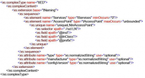
The power system automation community is going through a period of transition from the world of hard-wired systems and proprietary configuration and analysis tools into the world of distributed IEC 61850 communications-based systems and object-oriented standards-based engineering and analysis tools. This requires the development of a new set of skills to help the specialists from our industry understand and use the new technology. The main goal of this paper is to introduce the Extensible Markup Language (XML) and the Unified Modeling Language (UML) to the protection and control community and focus on the UML diagrams and XML files used in the IEC 61850 standard and some IEEE standards related to protection and control to help the readers understand the diagrams and files included in or defined by the different standards.
Examples of the use of UML diagrams in IEC 61850 are given later in the paper.
Examples of the use of XML in the IEEE C37.239: IEEE Standard for Common Format for Event Data
Exchange (COMFEDE) standards are presented at the end of the paper.
Old Lessons – Re-learned
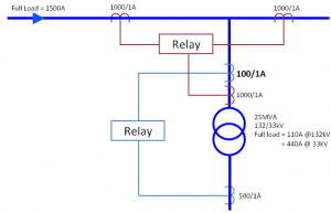
Over national holiday breaks, and weekends, especially during the spring and autumn, low loads and high proportional wind generation could combine and result in fault levels on the network dropping to unexpected values. In the event of a system fault, this could adversely affect the operation of protection schemes. If protection schemes do not detect faults the effects of system events will become more widespread leading to unnecessary damage to assets and power supply disruption. Looking at the operation of single-phase tripping schemes, this paper will discuss how the schemes work to clear a fault and the importance of ensuring tripping at all ends of the protected feeder with particular emphasis on Wind Farm fault supplying capability and protection scheme sensitivity looking at the various differential, distance and distance signal-aided line protection schemes. For transformer protection, we look at how basic relay settings are modified by zero-sequence filtering and ratio compensation leading to differing sensitivity.
Download full papers at the end of this page
330 kV downed conductor protection and successful operation
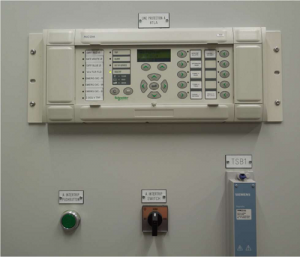
Line protection systems were replaced between Transgrid’s Upper Tumut Switching Station and Snowy Hydro’s Tumut 1 and Tumut 2 Power Stations. The risk of a downed conductor before synchronizing the line at the switching station was identified, and a protection system was designed to detect this failure. Traditional systems would not detect this unique event until a significant quantity of fault current was reached with a possible bush fire. The predicted event occurred less than a year after the protection was installed, and was correctly cleared with no extra plant or environmental damage. This paper examines the thought processes required to see the need, the need and implementation of the protection, and the resulting fault and protection operation.
The Reality of Providing Energy in Australia: Bushfire Mitigation and the Benefits of Power Quality Monitoring Outside Substations
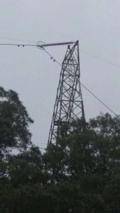
In Australia’s electricity supply history, utilities have grappled with some unique issues. Australian utilities are known for innovation, and the utility demands placed on manufacturers have been responsible for some of the greatest steps in switchgear development. As one of the largest interconnected networks in the world, distribution network service providers (DNSPs) in Australia face big issues presented by the unique geography and climate. One of the greatest causes for concern in the Australian Distribution community is the aspect of bushfire risk. Australia has a long history of bushfire disasters, but instead of the devastating events of February 2009, the impact of utilities has been burned into the Australian psyche. The resilience of Australia’s utilities and engineers prompts appropriate development to mitigate these risks, and this paper outlines some of the features available using one of the most common protective distribution switchgear devices: the automatic circuit recloser (ACR). ACRs humble beginnings as hydraulic devices in the mid-1900s have evolved greatly through the years through to semiconductor-controlled switches. These switches have proliferated across networks all over the globe, driven by the immediate reliability benefits and protection offered on a reasonable budget. Australia itself has had a fair share of manufacturers, and today there are thousands of NOJA Power reclosers in service providing reliability to customers. Driven by continuous requirements from utilities, these semiconductor-controlled reclosers have been greatly developed, and this paper presents some solutions implemented to combat the challenges of the Australian distribution network. Bushfire mitigation is at the forefront of development, and through the use of the NOJA Power RC10 control system, it is now possible to update and integrate bushfire mitigation strategies using commissioned NOJA Power assets, with a simple firmware update and a network integration strategy.
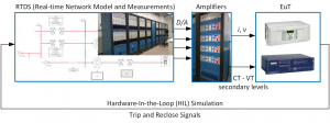
By using the onboard voltage and current sensing capabilities of these reclosers, the RC10 now can conduct complete power quality monitoring and reporting – a technology long bound to the granite yards of substations. This functionality is now available out on the feeders, using the same protection devices installed years ago, providing power quality feedback from the shores of the gold coast to Uluru. Enhancing Australian Protection System Testing through Real-Time Digital Simulations The modern power system is large and highly complex. At the same time, several new and potentially disruptive technologies can redefine the way the power system is designed, operated, and managed, changing long-existing network dynamics. Examples of these disruptive technologies include intermittent power generation (such as wind and large-scale solar PV farms), centralized energy storage, and distributed generation (DG). Meanwhile, computational power and sensing capacity is continuously increasing within the network. New generation network devices (including flexible alternating current transmission systems (FACTS) such as synchronous static compensators (STATCOMs), HVDC interconnections, multi-terminal dc networks, and dc grids) extend the available solutions but further complicate the optimal selection of technologies. This increased complexity also translates into requirements for more sophisticated and highly selective protection systems for faster fault detection and isolation, to minimize disruption and increase network availability. Improper settings or coordination among protection devices can lead to major network disruptions, as demonstrated in the 2003 North American Eastern Interconnection Blackout. Inadequate understanding of the power system and inadequate situational awareness are considered among the major causes of such failures. Recently, the aspect of grid resiliency has also attracted attention, in addition to the existing focus on reliability, efficiency, and cost-effectiveness. One of the main methods of demonstrating and verifying the performance of current and future power systems, thoroughly testing the design and operation of protection schemes, and experimenting with novel methods and approaches is through the use of real-time digital simulations. The concept of real-time digital simulations was initially introduced in 1969 by Dommel [3] and is based on the calculation of the system’s currents and voltages using the conductance matrix of an equivalent electrical network at a time smaller than the defined time-step [4]. The time step should be selected so that the real-time behavior of the network is accurately emulated and provides trustworthy results. Through real-time simulation, the behavior of the power system can be observed in real-time. At the same time, external hardware (e.g. digital controllers or protection relays) can be directly connected to the simulator enabling studies on the response of hardware and the response of the power system following any operation of the external device. The major drawback of this approach is that it requires large computational power and processing capabilities, which increase exponentially with the complexity of the simulated system. The typical time-step for real-time digital simulations is in the range of a few μs (up to 50μs). Real-time digital simulation can be a very powerful tool for network planners, protection engineers, and everyone involved in the design and operation of a power system. The objective of this article is to present the real-time digital simulator (RTDS) available at UNSW Australia, demonstrate its capabilities and illustrate applications relevant to protection testing as well as the broad range of simulations that can be performed.
Click here to download Proceedings of the Australian Protection Symposium


