

How to create a new CFC Chart
In the DIGSI 4 Manager first, you must open a device (offline or online). Afterward, a new window appears.
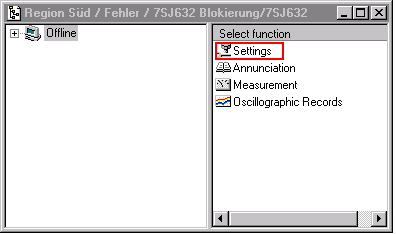
first view after opening a device parameter set
Click on the icon Settings. Now all folders of the domain Settings will appear. Click on the CFC chart and you will see the already existent CFC charts. Different devices have different default CFC charts.

Folders in domain Settings
If you want to create a new chart go to the Insert menu in the menu bar of the window where you see the folder Settings. In the Insert menu is one option available called CFC chart. If you click on it a new CFC chart will appear in the right window. The computer will name it with the default name CFC1. The name can be changed by clicking with the right mouse button on the new chart and choosing the item object properties. There the name can be typed again. With double-clicking on the inserted chart, you can open this new chart. If you do not want to have already existent CFC charts you can simply delete them by the right mouse button and choose the deleted item or directly from the delete button on the PC keypad.

After insert of a new CFC chart
Easy Interlocking
A simple example of the interlocking feature in SIPROTEC 4 devices is explained using the following sample application:
The circuit breaker (Q0) is only permitted to close when the disconnector (Q1) is closed and the ground switch (Q8) is opened.
Refer to the input/output matrix. In the group control device, the commands for the switching devices are indicated. Each command occupies two lines.
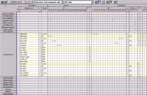
The commands in the input/output matrix
For example, the first line of the disconnector switch contains the command information which is routed to the output contacts. The second line is for the feedback signals which are derived via binary inputs.
Two binary inputs for feedback are required for double point indication i.e. if:
- the switch device is opened=off (first used binary input : high(1), second low (0))
- the switch device is closed=on (first used binary input : low (0), second high(1))
- the switch device is in an intermediate / not valid position (either 00 or 11).
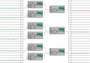
Controls without feedback can also be used, in this case, interlocking will not be possible. For interlocking, the feedback signals are the most important information. In this example, the interlocking must check the status of the disconnector (Q1) and the ground switch (Q8) before releasing a close command to the circuit breaker Q0. In picture 2 the CFC chart is shown. The status of the disconnector and ground switch is decoded with DI_TO_BOOL gates.
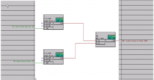
application of interlocking in CFC
The first DI_TO_BOOL gate decodes the closed position of the disconnector switch (Q1). The 2nd DI_TO_BOOL gate decodes the open position of the ground switch (Q8). If both these conditions are valid, the AND gate will generate the signal for releasing the
circuit breaker close command. The default settings already contain signals for interlocking (internal single point annunciations, see picture 1). For user-defined signals, these must first be created in the I/O matrix and routed to source CFC. Otherwise, these will not be available for selection later.
Ultimately the interlocking condition of the circuit breaker command must be allocated to the release signal derived with the logic. In the input/output matrix you have to click with the right mouse button on the circuit breaker and choose the object properties-item. The release signal Control Device 52 Close is responsible for the switching ON the circuit breaker.
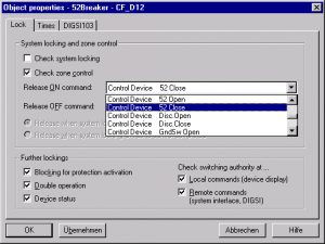
Object properties of the circuit breaker
For the control functions such as circuit breaker OFF or other devices, the same procedure must be carried out with the relevant interlocking conditions. The default settings of SIPROTEC 4 devices always contain a CFC chart with standard interlocking functions.
Extended CFC chart for interlocking of several switching devices
Thanks a lot…