The PC operating program DIGSI 4 is the user interface to all Siemens protection devices, up to and including SIPROTEC 4 and
SIPROTEC Compact. It has a simple and intuitive user interface. Using DIGSI 4, the parameters for the SIPROTEC devices are set
and evaluated – it is a tailor-made program for industrial and energy supply systems.
SICAMPAS/PQS has been designed as a modular system with open communication interfaces. It thus meets the requirements of state-of-the-art substation control and protection systems and the power management systems required for industrial manufacturing plants. Functions for power quality evaluation complement its versatile fields of application. The system component SICAM PAS UI – Configuration is responsible for:
• Configuration and parameterization of your plant
• Exchange of configuration data
IEC 61850 – Design a feeder
Example: Design a bay (one-and-half breaker) with distance and differential relays.
- The differential relay has a control LCD. So we want to control Q02 and Q03 with the relay.
- The diagram should be shown in LDC.
- Alarms and other parameters should send by the differential relay (GOOSE messages) and receive by the distance relay.
- Control from the control room

Configuration in DIGSI
At first, we should create the relays with relative MLFB. Add a Control Device group in the configuration matrix.
For simplicity, add Control Device 2 and Control Device 3 for CutOff2 and CutOff 3 respectively.
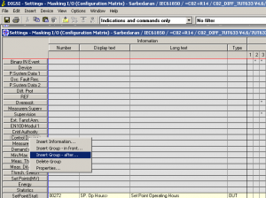

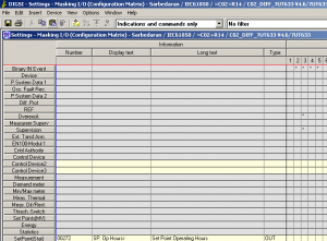
In Control Device2, select insert information for Q2. We want to control the Q2 form S=system and the position of Q2 with Binary Input (BI) 13 and 14.
If one of the inputs is true, it is open or closed. And if both of the BIs are true or false, it means an intermediate state.
From the list, select the Double point with zero states. Edit the name of the signal in Display text and Long text.
In the DP_I row (Dual Point indication), select BI 13 and 14 for Q2.
The source of the signal is System, so check the related box and set a name for that, here is Q2 and in switch type, select Disconnector.
Note: when we select the source for the signals, the Destination signals for BO with checked automatically. It means the signal will send to the system automatically.
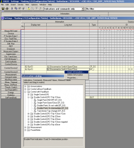
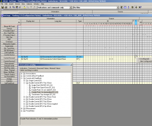
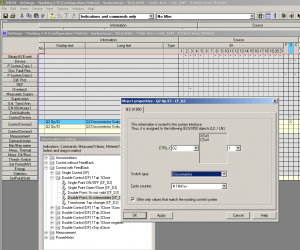
In Control Device2, select insert information for Q02. We want to control the Q02 form S=system and the position of Q02 with Binary Input (BI) 11 and 12.
If one of the inputs is true, it is open or closed. And if both of the BIs are true or false, it is intermediate.
From the list, select the Double point with zero states. Edit the name of the signal in Display text and Long text.
In the DP_I row (Dual Point indication), select BI 11 and 12 for Q02.
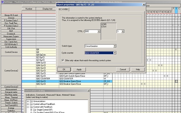
The source of the signal is System, so check the related box and set a name for that, here is Q2, and in switch type, select Circuit Breaker.
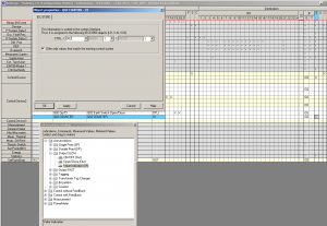
For a circuit breaker, we want to add the counter to count the number of open and closed positions. So form the signal list, select Value Indication (VI), and add it to the system.
For the source signal select Circuit Breaker for the switch type. And for the Cycle counter select the signal which is selected in Value Indication (VI).
Note: when we select the source for the signals, the Destination signals for BO with checked automatically. It means the signal will send to the system automatically.


Downloaded the file, it is very helpful for me, share more products on substation automation and IEC61850, update me for new products
Thanks for your comment and your interest, sure have your email we will keep you update to date
Hello,
I am interested in this course. Could you send me this package?
hello, the offer has been sent to your email, kindly check
Hola, estoy interesado en todo el paquete de IEC61850, Digsi 4 y Digsi 5.
podría mandarme información por favor.
josuemunozp@outlook.es
actually sent to u, dear Josue
I am failing to download, please help me download part 1 and part 11
Please send a request on WhatsApp: +989129613659
engmohaned66@gmail.com
Please send your request on WhatsApp: +989129613659
Can i get the ink ,So can i download
” SICAM SSC SOFTWARE FOW WINCC V7.4″