One of the common applications of GOOSE messages is to implement a ‘fast bus’ or ‘reverse interlocking’ bus protection scheme. In its most basic form, a directional overcurrent relay is installed on the incomer. If a fault is detected towards the bus the incomer relay will trip unless any of the feeder relays send it a blocking signal indicating that the fault is external to the bus.
Ideally, this type of scheme should be tested by primary or secondary injection into both the incomer and feeder relay at the same time. However, there are often cases when access to only a single relay at once is possible. Since IEC61850 is an international standard, the use of a third-party test tool is possible. One such test tool is the OMICRON CMC.
Method
The relay-relay GOOSE application is created in DIGSI IEC 61850 System Configurator. The pickup (‘start’) of the overcurrent elements in each of the feeder relays is mapped to a GOOSE input in the incomer relay. The configuration is via drag and drop – DIGSI automatically takes care of the necessary low-level details of the protocol.
DIGSI IEC 61850 System Configurator
If the GOOSE mapping has already been created in DIGSI, then getting this information into the OMICRON is as simple as exporting the Substation Configuration Description (SCD) file from DIGSI and importing it into the OMICRON GOOSE Configuration software. (Export DIGSI SCD file, and Import in to OMICRON GOOSE Configuration)
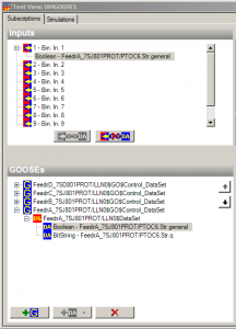
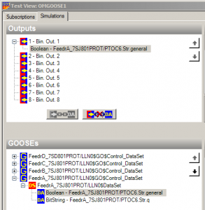
By connecting the OMICRON into either the subnet or directly into a relay, the OMICRON software allows the CMC to either simulate or subscribe to any of the stations. Again, the configuration of this is via drag and drop – the relevant goose data-set item is selected and mapped to a binary input or output of the CMC. These are then available for use as standard binary inputs/outputs in other parts of the Test Universe software.
GOOSE data set mapping in omicron
By use of the Omicron secondary injection combined with its GOOSE functions each of the SIPROTEC relays in the fast-bus scheme can be tested individually.
Test 1: Testing a feeder relay:
Testing of the feeder relay is to confirm that as soon as its overcurrent element picks up it transmits a suitable GOOSE blocking message. The Omicron is connected to inject a secondary current into the relay above the element pickup threshold. The Omicron is set to subscribe to the ‘Start’ GOOSE message expected to be transmitted by the relay. Since the SCD file was directly imported from DIGSI, all the protocol details of the GOOSE message will automatically be checked during the testing for conformance with what the incomer relay is expecting.
An Omicron test is created and executed to record the time taken from the injection of current to receipt of the GOOSE message. Typically times expected will be the pickup time of the relay element plus just a few milliseconds.
Test 2: Testing the incomer relay
The incomer relay is tested to confirm that when it receives a blocking message via GOOSE that its directional overcurrent element does not issue a trip (Figure 7). The OMICRON is configured to simulate the GOOSE message that would come from one of the feeder relays. For testing, activation of this GOOSE transmission is via any of the mapped binary output functions of the Test Universe application (Figure 6).
Using the State Sequencer, the first state can be set to inject voltage and current into the relay without any GOOSE message transmission. After a short time delay (to match that recorded in Test 1) the second state should keep the analog signals on, but activate the GOOSE message transmission by turning the relevant binary output on. A successful test is where the relay element does not trip.
Using a binary output to generate blocking GOOSE message
Testing Incomer blocking with received GOOSE message


hi how much course fee for DIGSI 4 + DIGSI 5 + IEC61850 + GOOSE
send me details in
maneeeshmani28@gmail.com
the offer has been sent to your email