
Line differential protection (87L):
The line differential protection consists of three protection functions, phase segregated differential protection function, sudden change current differential protection function and zero sequence current differential protection function.
These three functions are associated with achieving high sensitivity and reliability with capacitive charge current compensation and reliable phase selection during various system disturbances. The precise time
synchronization of sampling ensures the differential protection of both end IEDs to operate reliably
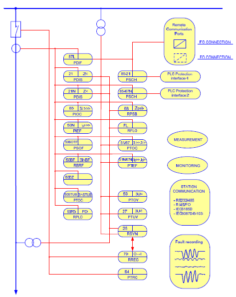
Distance protection (21, 21N)
The transmission line distance protection provides a five zones full scheme protection with all phase to phase faults and phase to earth fault loops independently for each zones.
Additionally, one extension zone is employed to co-operate with Auto-reclosing and tele-protection schemes.
Chapter 1 IED Introduction ………………………………………………………………………………………………… 1
Chapter 2 Local human machine interface ………………………………………………………………………… 3
1 Introduction ……………………………………………………………………………………………………………………… 4
2 Liquid crystal display(LCD) …………………………………………………………………………………………. 6
3 Keyboard ………………………………………………………………………………………………………………………… 7
4 IED menu ………………………………………………………………………………………………………………………… 8
4.1 Menu construction …………………………………………………………………………………………….. 8
4.2 Operation status ……………………………………………………………………………………………….. 9
4.3 Query reports ………………………………………………………………………………………………….. 10
4.4 Set time …………………………………………………………………………………………………………… 10
4.5 Contrast ………………………………………………………………………………………………………….. 10
4.6 Settings …………………………………………………………………………………………………………… 11
4.7 IED setting ………………………………………………………………………………………………………. 12
4.8 Test binary output ……………………………………………………………………………………………. 12
4.9 Testing operation …………………………………………………………………………………………….. 12
Chapter 3 Installing IED …………………………………………………………………………………………………… 13
1 Unpacking and checking the IED …………………………………………………………………………………… 14
2 Installing the IED …………………………………………………………………………………………………………… 15
3 IED connection ……………………………………………………………………………………………………………… 16
3.1 IED connector …………………………………………………………………………………………………. 16
3.1.1 Introduction ………………………………………………………………………………………………. 16
3.1.2 Terminals of Analogue Input Module (AIM) ………………………………………………. 17
3.1.3 Terminals of Binary Input Module (BIM) ……………………………………………………. 18
3.1.4 Terminals of Binary Output Module (AIM) …………………………………………………. 19
3.1.5 Terminals of Communication module (COM) ……………………………………………. 23
3.1.6 Communication ports of CPU module (CPU) ……………………………………………. 24
3.1.7 Terminals of Power Supply Module (PSM) ……………………………………………….. 25
3.1.8 RS232 port ………………………………………………………………………………………………. 26
3.2 Connecting to protective earth ………………………………………………………………………… 26
3.3 Connecting the power supply module ……………………………………………………………… 26
3.4 Connecting to CT and VT circuits ……………………………………………………………………. 26
3.5 Connecting the binary inputs and outputs ……………………………………………………….. 26
3.6 Making the screen connection …………………………………………………………………………. 28
3.7 Optical connections …………………………………………………………………………………………. 28
3.8 RS485 and RS232 ports connection ……………………………………………………………….. 29
3.8.1 RS485 port connection …………………………………………………………………………….. 29
3.8.2 RS232 port connection …………………………………………………………………………….. 29
3.9 Connecting the GPS ……………………………………………………………………………………….. 30
4 Checking before energizing …………………………………………………………………………………………… 31
4.1 Introduction ……………………………………………………………………………………………………… 31
4.2 Checking the protective earth connection ………………………………………………………… 31
4.3 Checking the power supply connection ……………………………………………………………. 31
4.4 Checking the CT and VT circuits connection …………………………………………………… 31
4.4.1 Checking the CT circuits connection ………………………………………………………… 31
4.4.2 Checking the VT connection …………………………………………………………………….. 32
4.5 Checking the binary input and output connection …………………………………………….. 32
4.5.1 Checking the binary input connection ……………………………………………………….. 32
4.5.2 Checking the binary output connection …………………………………………………….. 33
4.6 Checking the screened cables connection ………………………………………………………. 33
4.7 Checking the optical connections …………………………………………………………………….. 33
4.8 Checking the S485 and RS232 port connectios ………………………………………………. 33
4.8.1 Checking the RS485 port connection ……………………………………………………….. 33
4.8.2 Checking RS232 port connection ……………………………………………………………… 33
4.9 Checking GPS connection ………………………………………………………………………………. 33
4.10 Checking the insulation voltage and insulation resistance ……………………………….. 33
4.10.1 Checking the insulation voltage ………………………………………………………………… 34
4.10.2 Checking the insulation resistance …………………………………………………………… 34
5 Checking after energizing ………………………………………………………………………………………………. 35
5.1 Introduction ……………………………………………………………………………………………………… 35
5.2 Test LCD …………………………………………………………………………………………………………. 35
5.3 Test the keyboard ……………………………………………………………………………………………. 35
5.4 Setting the IED time ………………………………………………………………………………………… 35
5.5 Self-supervision HMI data ……………………………………………………………………………….. 36
5.6 Checking the software and hardware version ………………………………………………….. 36
Chapter 4 Read and change setting …………………………………………………………………………………. 37
1 Read and change the setting vaule ……………………………………………………………………………….. 38
1.1 Read and change the setting value via LHMI…………………………………………………… 38
1.1.1 Introduction ………………………………………………………………………………………………. 38
1.1.2 Communication parameter ……………………………………………………………………….. 38
1.1.3 Equipment parameter ……………………………………………………………………………….. 39
1.1.4 Setting values and binary settings for protection function …………………………. 39
2 Switching the setting group ……………………………………………………………………………………………. 48
2.1 Introduction ……………………………………………………………………………………………………… 48
2.2 Method for switching setting group via LHMI …………………………………………………… 48
2.3 Method for switching setting group via binary input …………………………………………. 48
Chapter 5 Testing the communication connection and time synchronization ……………………. 49
1 Testing the communication connection ………………………………………………………………………….. 50
1.1 Testing the Ethernet communication ……………………………………………………………….. 50
1.1.1 Testing the electrical Ethernet communication ………………………………………….. 50
1.1.2 Testing the optical Ethernet communication ……………………………………………… 50
1.2 Testing the RS485 port ……………………………………………………………………………………. 50
1.3 Testing the RS232 port ……………………………………………………………………………………. 50
2 Testing the time synchronization ……………………………………………………………………………………. 52
2.1 Network mode …………………………………………………………………………………………………. 52
2.2 Pulse mode …………………………………………………………………………………………………….. 52
2.3 IRIG-B mode …………………………………………………………………………………………………… 52
Chapter 6 IED testing ………………………………………………………………………………………………………. 53
1 Introduction ……………………………………………………………………………………………………………………. 54
2 Points for attention during testing ………………………………………………………………………………….. 56
3 Preparing for test …………………………………………………………………………………………………………… 58
3.1 Introduction ……………………………………………………………………………………………………… 58
3.2 Connecting test equipment to IED …………………………………………………………………… 58
4 Testing the power supply ……………………………………………………………………………………………….. 60
4.1 Checking the self-startup performance ……………………………………………………………. 60
4.2 DC power on and power off testing …………………………………………………………………. 60
4.3 Checking the expiry date of power supply ……………………………………………………….. 60
5 Checking the analog channel ………………………………………………………………………………………… 61
5.1 Checking the zero drift …………………………………………………………………………………….. 61
5.2 Calibrating ………………………………………………………………………………………………………. 61
5.3 Checking the accuracy and the linearity of analog quantitis …………………………….. 61
5.4 Checking the polarity of analog quantities ……………………………………………………….. 62
6 Testing binary input ……………………………………………………………………………………………………….. 63
7 Testing binary output ……………………………………………………………………………………………………… 64
8 Verifying the IED functions …………………………………………………………………………………………….. 65
8.1 Differential current protection ………………………………………………………………………….. 65
8.1.1 Loop test mode ………………………………………………………………………………………… 65
8.1.2 Normal mode ……………………………………………………………………………………………. 74
8.1.3 Completing the test ………………………………………………………………………………….. 83
8.1.4 Reference setting list for test ……………………………………………………………………. 83
8.2 Distance protection …………………………………………………………………………………………. 85
8.2.1 Verifying the settings ………………………………………………………………………………… 85
8.2.2 Completing the test ………………………………………………………………………………… 108
8.2.3 Reference setting list for test ………………………………………………………………….. 108
8.3 Power swing function …………………………………………………………………………………….. 111
8.3.1 Verifying the power swing function settings…………………………………………….. 111
8.3.2 Completing the test ………………………………………………………………………………… 111
8.3.3 Reference setting list for test ………………………………………………………………….. 111
8.4 Teleprotection for distance protection ……………………………………………………………. 112
8.4.1 Verifying the settings ………………………………………………………………………………. 112
8.4.2 Completing the test ………………………………………………………………………………… 124
8.4.3 Reference setting list for test ………………………………………………………………….. 124
8.5 Teleprotection for earth fault protection …………………………………………………………. 125
8.5.1 Verifying the settings ………………………………………………………………………………. 125
8.5.2 Completing the test ………………………………………………………………………………… 129
8.5.3 Reference setting list for test ………………………………………………………………….. 130
8.6 Overcurrent protection …………………………………………………………………………………… 130
8.6.1 Verifying the settings ………………………………………………………………………………. 131
8.6.2 Completing the test ………………………………………………………………………………… 135
8.6.3 Reference setting list for test ………………………………………………………………….. 136
8.7 Earth fault protection ……………………………………………………………………………………… 137
8.7.1 Verifying the settings ………………………………………………………………………………. 137
8.7.2 Completing the test …………………………………………………………………………………. 141
8.7.3 Reference setting list for test ………………………………………………………………….. 141
8.8 Emergency/backup overcurrent protection …………………………………………………….. 143
8.8.1 Verifying the settings ………………………………………………………………………………. 143
8.8.2 Completing the test …………………………………………………………………………………. 148
8.8.3 Reference setting list for test ………………………………………………………………….. 148
8.9 Emergency/backup earth fault protection ………………………………………………………. 149
8.9.1 Verifying the settings ………………………………………………………………………………. 149
8.9.2 Completing the test …………………………………………………………………………………. 153
8.9.3 Reference setting list for test ………………………………………………………………….. 153
8.10 Switch-onto-fault protection ……………………………………………………………………………. 154
8.10.1 Verifying the settings ………………………………………………………………………………. 154
8.10.2 Completing the test …………………………………………………………………………………. 164
8.10.3 Reference setting list for test ………………………………………………………………….. 165
8.11 Overload protection ……………………………………………………………………………………….. 166
8.11.1 Verifying the settings ………………………………………………………………………………. 166
8.11.2 Completing the test …………………………………………………………………………………. 168
8.11.3 Reference setting list for test ………………………………………………………………….. 168
8.12 Overvoltage protection …………………………………………………………………………………… 168
8.12.1 Verifying the settings ………………………………………………………………………………. 168
8.12.2 Completing the test …………………………………………………………………………………. 173
8.12.3 Reference setting list for test ………………………………………………………………….. 173
8.13 Undervoltage protection …………………………………………………………………………………. 174
8.13.1 Verifying the settings ………………………………………………………………………………. 174
8.13.2 Completing the test …………………………………………………………………………………. 179
8.13.3 Reference setting list for test ………………………………………………………………….. 180
8.14 Circuit breaker failure protection ……………………………………………………………………. 181
8.14.1 Verifying the settings of stage 1 of CBF protection………………………………….. 181
8.14.2 Completing the test …………………………………………………………………………………. 185
8.14.3 Reference setting list for test ………………………………………………………………….. 185
8.15 Dead zone protection …………………………………………………………………………………….. 186
8.15.1 Verifying the settings ………………………………………………………………………………. 186
8.15.2 Completing the test …………………………………………………………………………………. 187
8.15.3 Reference setting list for test ………………………………………………………………….. 187
8.16 STUB protection …………………………………………………………………………………………….. 188
8.16.1 Verifying the settings ………………………………………………………………………………. 188
8.16.2 Completing the test …………………………………………………………………………………. 189
8.16.3 Reference setting list for test ………………………………………………………………….. 189
8.17 Poles discordance protection …………………………………………………………………………. 190
8.17.1 Verifying the settings ………………………………………………………………………………. 190
8.17.2 Completing the test …………………………………………………………………………………. 193
8.17.3 Reference setting list for test ………………………………………………………………….. 193
8.18 Synchro-check and energizing check function ………………………………………………. 193
8.18.1 Verifying the settings ………………………………………………………………………………. 193
8.18.2 Completing the test ………………………………………………………………………………… 204
8.18.3 Reference setting list for test ………………………………………………………………….. 204
8.19 Auto-reclosing ……………………………………………………………………………………………….. 205
8.19.1 Verifying the settings ………………………………………………………………………………. 205
8.19.2 Completing the test ………………………………………………………………………………… 207
8.19.3 Reference setting list for test ………………………………………………………………….. 207
8.20 Current transformer secondary circuit supervision …………………………………………. 209
8.20.1 Verifying the settings ………………………………………………………………………………. 209
8.20.2 Completing the test ………………………………………………………………………………… 210
8.20.3 Reference setting list for test ………………………………………………………………….. 210
8.21 Voltage transformer secondary circuit supervision ………………………………………… 210
8.21.1 Verifying the settings ………………………………………………………………………………. 211
8.21.2 Completing the test ………………………………………………………………………………… 216
8.21.3 Reference setting list for test ………………………………………………………………….. 217
8.22 Monitoring function ………………………………………………………………………………………… 217
8.22.1 Phase sequence of voltage and current monitoring ………………………………… 217
8.22.2 3I0 polarity monitoring ……………………………………………………………………………. 218
8.22.3 Monitoring third harmonic of voltage ………………………………………………………. 218
8.22.4 Reference voltage monitoring…………………………………………………………………. 219
8.22.5 Auxiliary contact of circuit breaker monitoring ………………………………………… 220
8.22.6 Broken conductor monitoring ………………………………………………………………….. 220
9 Checking before operation …………………………………………………………………………………………… 223
9.1 Checking the LED …………………………………………………………………………………………. 223
9.2 Checking the display on LCD ………………………………………………………………………… 223
9.3 Checking the clock ………………………………………………………………………………………… 223
9.4 Checking the voltage and current ………………………………………………………………….. 223
9.5 Checking the setting group ……………………………………………………………………………. 223
9.6 Checking the setting ……………………………………………………………………………………… 223
9.7 Checking the binary input ………………………………………………………………………………. 224
9.8 Checking the normal operation mode ……………………………………………………………. 224
9.8.1 Trip and close test with the circuit breaker ……………………………………………… 224
9.9 Put into operation ………………………………………………………………………………………….. 224
Chapter 7 Operating maintenance …………………………………………………………………………………. 225
1 Attentions during operating ………………………………………………………………………………………….. 226
2 Routine checking …………………………………………………………………………………………………………. 228
3 Periodical checking ……………………………………………………………………………………………………… 229
4 Operation after updating software or replacing modules ……………………………………………… 230
4.1 Operation after updating software or replacing CPU module …………………………. 230
4.2 Operation after updating software or replacing communication module…………. 230
4.3 Operation after replacing the binary input or output module ………………………….. 231
4.4 Operation after replacing the analog input module ………………………………………… 231
4.5 Operation after replacing power supply module …………………………………………….. 231
5 The alarm information and measure …………………………………………………………………………….. 232
5.1 Alarm information class I and the measure ……………………………………………………. 232
5.2 Alarm information class II and the measure …………………………………………………… 232
Chapter 8 Transportation and storage ……………………………………………………………………………. 235
1 Transportion…………………………………………………………………………………………………………………. 236
2 Storage ………………………………………………………………………………………………………………………… 237
Chapter 9 Appendix ……………………………………………………………………………………………………….. 239
1 Arrangement diagram of modules ………………………………………………………………………………… 240
2 Typical diagram ……………………………………………………………………………………………………………. 241
I am from Maharashtra State Electricity Transmission Company Private Limited.
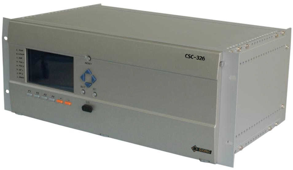
CSC 326 relay manual is needed for 220kV Theur S/s