
- Local human-machine interface
- 4 IED menu
- 4.2 Operation status ………………………………………………………………………………………………… 9
- 4.3 Query reports ………………………………………………………………………………………………….. 10
- 4.4 Set time …………………………………………………………………………………………………………… 10
- 4.5 Contrast …………………………………………………………………………………………………………… 10
- 4.6 Settings …………………………………………………………………………………………………………… 11
- 4.7 IED setting ………………………………………………………………………………………………………. 11
- 4.8 Test binary output ……………………………………………………………………………………………. 12
- 4.9 Testing operation …………………………………………………………………………………………….. 12
- 3.1.2 Terminals of Analogue Input Module (AIM) ……………………………………………….. 17
- 3.1.3 Terminals of Binary Input Module (BIM) ……………………………………………………. 18
- 3.1.4 Terminals of Binary Output Module (BOM) ……………………………………………….. 19
- 3.1.5 Terminals of Communication module (COM) ……………………………………………. 23
- 3.1.6 Communication ports of CPU module (CPU) ……………………………………………. 24
- 3.1.7 Terminals of Power Supply Module (PSM) ……………………………………………….. 25
- 3.1.8 RS232 port ……………………………………………………………………………………………….. 26
- 3.2 Connecting to Protective Earth…………………………………………………………………………. 26
- 3.3 Connecting the power supply module ……………………………………………………………… 26
- 3.4 Connecting to CT and VT circuits ……………………………………………………………………. 26
- 3.5 Connecting the binary inputs and outputs………………………………………………………… 26
- 3.6 Making the screen connection …………………………………………………………………………. 28
- 3.7 Optical connections …………………………………………………………………………………………. 28
- 3.8 RS485 and RS232 ports connection ……………………………………………………………….. 29
- 3.8.1 RS485 port connection …………………………………………………………………………….. 29
- 3.8.2 RS232 port connection …………………………………………………………………………….. 29
- 3.9 Connecting the GPS………………………………………………………………………………………… 30
- 4 Checking before energizing …………………………………………………………………………………………… 31
- Checking the power supply connection …………………………………………………………… 31
- 4.4 Checking the CT and VT circuits connection …………………………………………………… 31
- 4.4.1 Checking the CT circuits connection ………………………………………………………… 31
- 4.4.2 Checking the VT connection …………………………………………………………………….. 32
- 4.5 Checking the binary input and output connection ……………………………………………. 32
- 4.5.1 Checking the binary input connection ………………………………………………………. 32
- 4.5.2 Checking the binary output connection …………………………………………………….. 33
- 4.6 Checking the screened cables connection ………………………………………………………. 33
- 4.7 Checking the optical connections ……………………………………………………………………. 33
- 4.8 Checking the S485 and RS232 port connections ………………………………………………. 33
- 4.8.1 Checking the RS485 port connection ……………………………………………………….. 33
- 4.8.2 Checking RS232 port connection …………………………………………………………….. 33
- 4.9 Checking GPS connection ………………………………………………………………………………. 33
- 4.10 Checking the insulation voltage and insulation resistance ………………………………. 33
- 4.10.1 Checking the insulation voltage ……………………………………………………………….. 34
- 4.10.2 Checking the Insulation Resistance…………………………………………………………… 34
- 5 Checking after energizing ……………………………………………………………………………………………… 35
- 5.2 Test LCD …………………………………………………………………………………………………………. 35
- 5.3 Test the keyboard ……………………………………………………………………………………………. 35
- 5.4 Setting the IED time ………………………………………………………………………………………… 35
- 5.5 Self-supervision HMI data ……………………………………………………………………………….. 36
- 5.6 Checking the software and hardware version ………………………………………………….. 36
- Chapter 4 Read and change setting ………………………………………………………………………………… 37
- 1 Read and change the setting value ……………………………………………………………………………….. 38
- 1.1 Read and change the setting value via LHMI ………………………………………………….. 38
- 1.1.1 Introduction ………………………………………………………………………………………………. 38
- 1.1.2 Communication parameter ……………………………………………………………………….. 38
- 1.1.3 Equipment parameter ………………………………………………………………………………. 39
- 1.1.4 Setting values and binary settings for protection function …………………………. 39
- 2 Switching the setting group ……………………………………………………………………………………………. 46
- 2.1 Introduction ……………………………………………………………………………………………………… 46
- 2.2 Method for switching setting group via LHMI …………………………………………………… 46
- 2.3 Method for switching setting group via binary input …………………………………………. 46
- Chapter 5 Testing the communication connection and time synchronization ……………………. 47
- 1 Testing the communication connection ………………………………………………………………………….. 48
- 1.1 Testing the Ethernet communication ……………………………………………………………….. 48
- 1.1.1 Testing the electrical Ethernet communication …………………………………………. 48
- 1.1.2 Testing the optical Ethernet communication ……………………………………………… 48
- 1.2 Testing the RS485 port……………………………………………………………………………………. 48
- 1.3 Testing the RS232 port……………………………………………………………………………………. 48
- 2 Testing the time synchronization ……………………………………………………………………………………. 50
- 2.1 Network mode …………………………………………………………………………………………………. 50
- 2.2 Pulse mode ……………………………………………………………………………………………………… 50
- 2.3 IRIG-B mode ……………………………………………………………………………………………………. 50
- Chapter 6 IED testing ………………………………………………………………………………………………………. 51
- 1 Introduction ……………………………………………………………………………………………………………………. 52
- 2 Points for attention during testing…………………………………………………………………………………… 54
- 3 Preparing for test …………………………………………………………………………………………………………… 56
- 3.1 Introduction ……………………………………………………………………………………………………… 56
- 3.2 Connecting test equipment to IED …………………………………………………………………… 56
- 4 Testing the power supply ……………………………………………………………………………………………….. 58
- 4.1 Checking the self-startup performance ……………………………………………………………. 58
- 4.2 DC power on and power off testing………………………………………………………………….. 58
- 4.3 Checking the expiry date of power supply ……………………………………………………….. 58
- 5 Checking the analog channel ………………………………………………………………………………………… 59
- 5.1 Checking the zero drift …………………………………………………………………………………….. 59
- 5.2 Calibrating ……………………………………………………………………………………………………….. 59
- 5.3 Checking the accuracy and the linearity of analog quantitis …………………………….. 60
- 5.4 Checking the polarity of analog quantities ……………………………………………………….. 60
- 6 Testing binary input ……………………………………………………………………………………………………….. 62
- 7 Testing binary output ……………………………………………………………………………………………………… 63
- 8 Verifying the IED functions …………………………………………………………………………………………….. 64
- 8.1 Instantaneous differential protection ………………………………………………………………… 64
- 8.1.1 Verifying the settings ………………………………………………………………………………… 64
- 8.1.2 Completing the test ………………………………………………………………………………… 66
- 8.1.3 Reference setting list for test ……………………………………………………………………. 66
- 8.2 Percentage differential protection ……………………………………………………………………. 66
- 8.2.1 Verifying the settings ………………………………………………………………………………… 66
- 8.2.2 Completing the test ………………………………………………………………………………… 76
- 8.2.3 Reference setting list for test ……………………………………………………………………. 77
- 8.3 Restricted earth fault protection……………………………………………………………………….. 79
- 8.3.1 Verifying the settings ………………………………………………………………………………… 79
- 8.3.2 Completing the test ………………………………………………………………………………… 81
- 8.3.3 Reference setting list for test ……………………………………………………………………. 81
- 8.4 Overexcitation protection …………………………………………………………………………………. 83
- 8.4.1 Verifying the settings ………………………………………………………………………………… 83
- 8.4.2 Completing the test ………………………………………………………………………………… 88
- 8.4.3 Reference setting list for test ……………………………………………………………………. 88
- 8.5 Overcurrent protection …………………………………………………………………………………….. 90
- 8.5.1 Verifying the settings ………………………………………………………………………………… 90
- 8.5.2 Completing the test …………………………………………………………………………………… 97
- 8.5.3 Reference setting list for test ……………………………………………………………………. 97
- 8.6 Earth fault protection ……………………………………………………………………………………… 103
- 8.6.1 Verifying the settings ………………………………………………………………………………. 103
- 8.6.2 Completing the test …………………………………………………………………………………. 109
- 8.6.3 Reference setting list for test ………………………………………………………………….. 110
- 8.7 Neutral earth fault protection …………………………………………………………………………. 115
- 8.7.1 Verifying the settings ………………………………………………………………………………. 115
- 8.7.2 Completing the test ………………………………………………………………………………… 121
- 8.7.3 Reference setting list for test ………………………………………………………………….. 122
- 8.8 Thermal overload protection ………………………………………………………………………….. 127
- 8.8.1 Verifying the settings ………………………………………………………………………………. 127
- 8.8.2 Completing the test ………………………………………………………………………………… 137
- 8.8.3 Reference setting list for test ………………………………………………………………….. 137
- 8.9 Overload protection ……………………………………………………………………………………….. 138
- 8.9.1 Verifying the settings ………………………………………………………………………………. 138
- 8.9.2 Completing the test ………………………………………………………………………………… 142
- 8.9.3 Reference setting list for test ………………………………………………………………….. 142
- 8.10 Overvoltage protection ………………………………………………………………………………….. 144
- 8.10.1 Verifying the settings ………………………………………………………………………………. 144
- 8.10.2 Completing the test ………………………………………………………………………………… 150
- 8.10.3 Reference setting list for test ………………………………………………………………….. 150
- 8.11 Circuit breaker failure protection ……………………………………………………………………. 151
- 8.11.1 Verifying the settings ………………………………………………………………………………. 152
- 8.11.2 Completing the test ………………………………………………………………………………… 156
- 8.11.3 Reference setting list for test ………………………………………………………………….. 156
- 8.12 Dead zone protection …………………………………………………………………………………….. 158
- 8.12.1 Verifying the settings ………………………………………………………………………………. 158
- 8.12.2 Completing the test ………………………………………………………………………………… 161
- 8.12.3 Reference setting list for test ………………………………………………………………….. 161
- 8.13 STUB protection ……………………………………………………………………………………………. 161
- 8.13.1 Verifying the settings ………………………………………………………………………………. 162
- 8.13.2 Completing the test ………………………………………………………………………………… 164
- 8.13.3 Reference setting list for test ………………………………………………………………….. 164
- 8.14 Poles discordance protection ………………………………………………………………………… 164
- 8.14.1 Verifying the settings ………………………………………………………………………………. 165
- 8.14.2 Completing the test ………………………………………………………………………………… 169
- 8.14.3 Reference setting list for test ………………………………………………………………….. 169
- 8.15 Voltage transformer secondary circuit supervision ………………………………………… 170
- 8.15.1 Verifying the settings ………………………………………………………………………………. 170
- 8.15.2 Completing the test ………………………………………………………………………………… 181
- 8.15.3 Reference setting list for test ………………………………………………………………….. 181
- 9 Checking before operation …………………………………………………………………………………………… 183
- 9.1 Checking the LED …………………………………………………………………………………………. 183
- 9.2 Checking the display on LCD ………………………………………………………………………… 183
- 9.3 Checking the clock ………………………………………………………………………………………… 183
- 9.4 Checking the voltage and current ………………………………………………………………….. 183
- 9.5 Checking the setting group ……………………………………………………………………………. 183
- 9.6 Checking the setting ……………………………………………………………………………………… 183
- 9.7 Checking the binary input ………………………………………………………………………………. 184
- 9.8 Checking the normal operation mode …………………………………………………………….. 184
- 9.8.1 Trip and close test with the circuit breaker ………………………………………………. 184
- 9.9 Put into operation …………………………………………………………………………………………… 184
- Chapter 7 Operating maintenance …………………………………………………………………………………. 186
- 1 Attentions during operating ………………………………………………………………………………………….. 187
- 2 Routine checking …………………………………………………………………………………………………………. 189
- 3 Periodical checking ……………………………………………………………………………………………………… 190
- 4 Operation after updating software or replacing modules ………………………………………………. 191
- 4.1 Operation after updating software or replacing CPU module …………………………. 191
- 4.2 Operation after updating software or replacing communication module …………. 191
- 4.3 Operation after replacing the binary input or output module …………………………… 192
- 4.4 Operation after replacing the analog input module ………………………………………… 192
- 4.5 Operation after replacing power supply module …………………………………………….. 192
- 5 The alarm information and measure …………………………………………………………………………….. 193
- 5.1 Alarm information and the measure ……………………………………………………………….. 193
- Chapter 8 Transportation and storage ……………………………………………………………………………. 196
- 1 Transportion…………………………………………………………………………………………………………………. 197
- 2 Storage ………………………………………………………………………………………………………………………… 198
- Chapter 9 Appendix ……………………………………………………………………………………………………….. 200
- 1 Arrangement diagram of modules ………………………………………………………………………………… 201
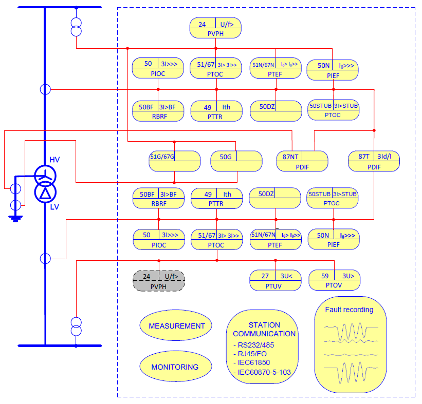
- 2 Typical diagram ……………………………………………………………………………………………………………. 202
- Chapter 2 Basic protection elements ………………………………………………………………….. 9
- 1 Startup element ……………………………………………………………………………………………10
- 1.1 Introduction ……………………………………………………………………………………..10
- 1.2 Sudden-change current startup element ………………………………………………10
- 1.3 Differential current startup element ……………………………………………………..10
- 2 Input and output signals ……………………………………………………………………………….. 11
- 3 Settings ………………………………………………………………………………………………………13
- 4 Report ………………………………………………………………………………………………………..16
- Chapter 3 Differential protection ………………………………………………………………………..17
- 1 Introduction …………………………………………………………………………………………………18
- 2 Applications…………………………………………………………………………………………………18
- 3 Protection algorithm ……………………………………………………………………………………..19
- 3.1 Differential and restraint current calculation ………………………………………….20
- 3.2 Automatic Ratio compensation …………………………………………………………..22
- 3.3 Automatic Vector group and zero sequence current compensation …………..26
- 4 Protection principle……………………………………………………………………………………….32
- 4.1 Instantaneous differential protection characteristic …………………………………32
- 4.2 Treble slope percent differential protection characteristic ………………………..34
- 4.3 Selective inrush stabilization schemes …………………………………………………37
- 4.3.1 2nd harmonic stabilization …………………………………………………………………38
- 4.3.2 Fuzzy recognition of inrush based on the waveform ………………………………38
- 4.4 Overexcitation stabilization ………………………………………………………………..40
- 4.5 CT Failure supervision ………………………………………………………………………42
- 4.6 CT Saturation supervision ………………………………………………………………….43
- 4.7 Differential current supervision……………………………………………………………44
- 5 Input and output signals ………………………………………………………………………………..46
- 6 Settings ………………………………………………………………………………………………………47
- 7 Report ………………………………………………………………………………………………………..50
- 8 Technical data ……………………………………………………………………………………………..51
- Chapter 4 Restricted earth fault protection ………………………………………………………….53
- 1 Introduction …………………………………………………………………………………………………54
- 2 Applications…………………………………………………………………………………………………54
- 3 Protection principle……………………………………………………………………………………….56
- 3.1 Differential and restraint current calculation ………………………………………….57
- 3.2 Automatic Ratio compensation …………………………………………………………..59
- 3.3 Positive sequence current blocking ……………………………………………………..61
- 3.4 Restricted earth fault current alarm ……………………………………………………..62
- 4 Input and output signals ………………………………………………………………………………..63
- 5 Settings ………………………………………………………………………………………………………64
- 6 Report ………………………………………………………………………………………………………. 66
- 7 Technical data …………………………………………………………………………………………….. 67
- Chapter 5 Overexcitation protection ………………………………………………………………….. 69
- 1 Introduction ………………………………………………………………………………………………… 70
- 2 Protection principle ……………………………………………………………………………………… 70
- 2.1 Protection principle ………………………………………………………………………….. 70
- 2.2 Voltage channel configuration …………………………………………………………… 76
- 3 Input and output signals ……………………………………………………………………………….. 77
- 4 Settings …………………………………………………………………………………………………….. 78
- 5 Report ………………………………………………………………………………………………………. 79
- 6 Technical data …………………………………………………………………………………………….. 80
- Chapter 6 Overcurrent protection……………………………………………………………………… 83
- 1 Introduction ………………………………………………………………………………………………… 84
- 2 Protection principle ……………………………………………………………………………………… 84
- 2.1 Protection Elements ………………………………………………………………………… 84
- 2.2 Inrush Restraint Feature …………………………………………………………………… 86
- 2.3 Direction Determination Feature ………………………………………………………… 87
- 2.4 CBF initiation Feature ……………………………………………………………………… 90
- 3 Input and output signals ……………………………………………………………………………….. 91
- 4 Setting ………………………………………………………………………………………………………. 92
- 5 Report ………………………………………………………………………………………………………. 99
- 6 Technical data …………………………………………………………………………………………….. 99
- Chapter 7 Earth fault protection ……………………………………………………………………… 101
- 1 Protection principle ……………………………………………………………………………………. 102
- 1.1 Protection elements ………………………………………………………………………. 102
- 1.2 Inrush Restraint Feature …………………………………………………………………. 104
- 1.3 Direction Determination Feature ………………………………………………………. 105
- 1.4 CBF initiation Feature ……………………………………………………………………. 107
- 2 Input and output signals ……………………………………………………………………………… 108
- 3 Setting …………………………………………………………………………………………………….. 109
- 4 Report …………………………………………………………………………………………………….. 115
- 5 Technical data …………………………………………………………………………………………… 116
- Chapter 8 Neutral earth fault protection …………………………………………………………… 119
- 1 Protection principle ……………………………………………………………………………………. 120
- 1.1 Protection Elements ………………………………………………………………………. 120
- 1.2 Inrush Restraint Feature …………………………………………………………………. 122
- 1.3 Direction Determination Feature ………………………………………………………. 122
- 1.4 CBF initiation Feature ……………………………………………………………………. 124
- 2 Input and output signals ……………………………………………………………………………… 125
- 3 Setting …………………………………………………………………………………………………….. 126
- 4 Report …………………………………………………………………………………………………….. 132
- 5 Technical data …………………………………………………………………………………………… 133
- Chapter 9 Thermal overload protection ……………………………………………………………. 135
- 1 Introduction ………………………………………………………………………………………………. 136
- 2 Protection principle…………………………………………………………………………………….. 136
- 3 Input and output signals ……………………………………………………………………………… 138
- 4 Setting ……………………………………………………………………………………………………… 138
- 5 Report ……………………………………………………………………………………………………… 140
- 6 Technical data …………………………………………………………………………………………… 141
- Chapter 10 Overload protection ……………………………………………………………………….. 143
- 1 Protection principle…………………………………………………………………………………….. 144
- 2 Input and output signals ……………………………………………………………………………… 145
- 3 Setting ……………………………………………………………………………………………………… 146
- 4 Report ……………………………………………………………………………………………………… 148
- Chapter 11 Overvoltage protection ……………………………………………………………………. 149
- 5 Introduction ………………………………………………………………………………………………. 150
- 6 Protection principle…………………………………………………………………………………….. 150
- 6.1 Phase to phase overvoltage protection ……………………………………………… 150
- 6.2 Phase to earth overvlotage protection……………………………………………….. 151
- 7 Logic diagram …………………………………………………………………………………………… 151
- 8 Input and output signals ……………………………………………………………………………… 151
- 9 Setting ……………………………………………………………………………………………………… 152
- 10 Report ……………………………………………………………………………………………….. 154
- 11 Technical data …………………………………………………………………………………….. 154
- Chapter 12 Circuit breaker failure protection ………………………………………………………. 157
- 1 Introduction ………………………………………………………………………………………………. 158
- 2 Protection principle…………………………………………………………………………………….. 158
- 3 Logic diagram …………………………………………………………………………………………… 161
- 4 Input and output signals ……………………………………………………………………………… 163
- 5 Setting ……………………………………………………………………………………………………… 164
- 6 Report ……………………………………………………………………………………………………… 167
- 7 Technical data …………………………………………………………………………………………… 167
- Chapter 13 Dead zone protection ……………………………………………………………………… 169
- 1 Introduction ………………………………………………………………………………………………. 170
- 2 Protection principle…………………………………………………………………………………….. 170
- 2.1 Function description……………………………………………………………………….. 171
- 3 Logic diagram …………………………………………………………………………………………… 171
- 4 Input and output signals ……………………………………………………………………………… 172
- 5 Setting ……………………………………………………………………………………………………… 173
- 6 Report ……………………………………………………………………………………………………… 174
- 7 Technical data …………………………………………………………………………………………… 174
- Chapter 14 STUB protection ……………………………………………………………………………. 175
- 1 Introduction ………………………………………………………………………………………………. 176
- 2 Protection principle…………………………………………………………………………………….. 176
- 2.1 Function description……………………………………………………………………….. 176
- 3 Logic diagram …………………………………………………………………………………………… 177
- 4 Input and output signals ……………………………………………………………………………… 177
- 5 Setting ……………………………………………………………………………………………………… 178
- 6 Report …………………………………………………………………………………………………….. 180
- 7 Technical data …………………………………………………………………………………………… 181
- Chapter 15 Poles discordance protection ………………………………………………………….. 183
- 1 Introdcution ………………………………………………………………………………………………. 184
- 2 Protection principle ……………………………………………………………………………………. 184
- 2.1 Function description ………………………………………………………………………. 184
- 3 Logic diagram …………………………………………………………………………………………… 185
- 4 Input and output signals ……………………………………………………………………………… 186
- 5 Setting …………………………………………………………………………………………………….. 187
- 6 Report …………………………………………………………………………………………………….. 188
- 7 Technical data …………………………………………………………………………………………… 188
- Chapter 16 Secondary system supervision ………………………………………………………… 189
- 1 VT failure supervision function …………………………………………………………………….. 190
- 2 Function principle ……………………………………………………………………………………… 190
- 3 Input and output signals ……………………………………………………………………………… 193
- 4 Setting …………………………………………………………………………………………………….. 194
- 5 Report …………………………………………………………………………………………………….. 195
- 6 Technical data …………………………………………………………………………………………… 196
- Chapter 17 External BIs to trip BOs ………………………………………………………………….. 197
- 1 Introduction ………………………………………………………………………………………………. 198
- 2 Function principle ……………………………………………………………………………………… 198
- 3 BI Trigger Record ……………………………………………………………………………………… 199
- 4 BI Switch SetGroup …………………………………………………………………………………… 200
- 5 BI “Blk Rem Access” and “RELAY TEST” ………………………………………………………. 200
- 6 BI “BI_Config1~ BI_Config2” and “BI TRIGGER DR1~ 10” ………………………………. 201
- 7 Setting …………………………………………………………………………………………………….. 201
- Chapter 18 Station communication …………………………………………………………………… 203
- 1 Overview …………………………………………………………………………………………………. 204
- 1.1 Protocol ……………………………………………………………………………………….. 204
- 1.1.1 LON communication protocol ……………………………………………………. 204
- 1.1.2 IEC61850-8 communication protocol ………………………………………….. 204
- 1.1.3 IEC60870-5-103 communication protocol ……………………………………. 205
- 1.2 Communication port ………………………………………………………………………. 205
- 1.2.1 Front communication port …………………………………………………………. 205
- 1.2.2 RS485 communication ports ……………………………………………………… 205
- 1.2.3 Ethernet communication ports …………………………………………………… 205
- 1.3 Technical data ………………………………………………………………………………. 205
- Front communication port …………………………………………………………………………………. 206
- RS485 communication port ………………………………………………………………………………. 206
- 2 Typicalcommunication scheme ……………………………………………………………………. 208
- 2.1 Typical substation communication scheme ………………………………………… 208
- 2.2 Typical time synchronizing scheme ………………………………………………….. 208
- Chapter 19 Hardware …………………………………………………………………………………….. 211
- This chapter describes the IED hardware. …………………………………………………………… 211
- 3 Introduction ………………………………………………………………………………………………. 212
- 3.1 IED structure ………………………………………………………………………………… 212
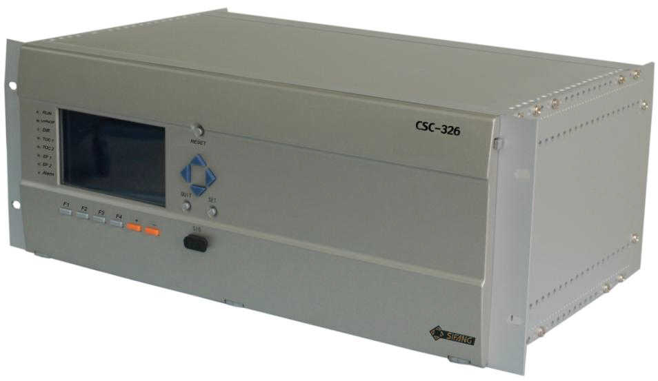
- 3.2 IED appearance …………………………………………………………………………….. 212
- 3.3 IED module arrangement ………………………………………………………………… 213
- 3.4 The rear view of the protection IED …………………………………………………… 213
- 4 Local human-machine interface …………………………………………………………………… 214
- 4.1 Human machine interface ……………………………………………………………….. 214
- 4.2 LCD …………………………………………………………………………………………….. 215
- 4.3 Keypad ………………………………………………………………………………………… 215
- 4.4 Shortcut keys and functional keys …………………………………………………….. 216
- 4.5 LED …………………………………………………………………………………………….. 217
- 4.6 Front communication port ……………………………………………………………….. 218
- 5 Analog input module ………………………………………………………………………………….. 219
- 5.1 Introduction …………………………………………………………………………………… 219
- 5.2 Terminals of Analogue Input Module (AIM) ………………………………………… 219
- 5.3 Technical data ……………………………………………………………………………….. 220
- 5.3.1 Internal current transformer ……………………………………………………….. 220
- 5.3.2 Internal voltage transformer ………………………………………………………. 221
- 6 Communication module ……………………………………………………………………………… 222
- 6.1 Introduction …………………………………………………………………………………… 222
- 6.2 Substaion communication port …………………………………………………………. 222
- 6.2.1 RS232 communication ports ……………………………………………………… 222
- 6.2.2 RS485 communication ports ……………………………………………………… 222
- 6.2.3 Ethernet communication ports……………………………………………………. 222
- 6.2.4 Time synchronization port …………………………………………………………. 223
- 6.3 Terminals of Communication Module ………………………………………………… 223
- 6.4 Operating reports …………………………………………………………………………… 224
- 6.5 Technical data ……………………………………………………………………………….. 224
- 6.5.1 Front communication port …………………………………………………………. 224
- 6.5.2 RS485 communication port ……………………………………………………….. 225
- 6.5.3 Ethernet communication port …………………………………………………….. 225
- 6.5.4 Time synchronization ……………………………………………………………….. 226
- 7 Binary input module …………………………………………………………………………………… 227
- 7.1 Introduction …………………………………………………………………………………… 227
- 7.2 Terminals of Binary Input Module (BIM) …………………………………………….. 227
- 7.3 Technical data ……………………………………………………………………………….. 229
- 8 Binary output module …………………………………………………………………………………. 230
- 8.1 Introduction …………………………………………………………………………………… 230
- 8.2 Terminals of Binary Output Module (BOM) …………………………………………. 230
- 8.2.1 Binary Output Module A ……………………………………………………………. 230
- 8.2.2 Binary Output Module C ……………………………………………………………. 233
- 8.3 Technical data ……………………………………………………………………………….. 234
- 9 Power supply module …………………………………………………………………………………. 236
- 9.1 Introduction …………………………………………………………………………………… 236
- 9.2 Terminals of Power Supply Module (PSM) ………………………………………… 236
- 9.3 Technical data ………………………………………………………………………………. 238
- 10 Techinical data ……………………………………………………………………………………. 239
- 10.1 Basic data ……………………………………………………………………………………. 239
- 10.1.1 Frequency ……………………………………………………………………………… 239
- 10.1.2 Internal current transformer ………………………………………………………. 239
- 10.1.3 Internal voltage transformer ………………………………………………………. 239
- 10.1.4 Auxiliary voltage ……………………………………………………………………… 239
- 10.1.5 Binary inputs…………………………………………………………………………… 240
- 10.1.6 Binary outputs ………………………………………………………………………… 240
- 10.2 Type tests …………………………………………………………………………………….. 241
- 10.2.1 Product safety-related Tests ……………………………………………………… 241
- 10.2.2 Electromagnetic immunity tests …………………………………………………. 242
- 10.2.3 DC voltage interruption test ………………………………………………………. 244
- 10.2.4 Electromagnetic emission test …………………………………………………… 244
- 10.2.5 Mechanical tests ……………………………………………………………………… 244
- 10.2.6 Climatic tests ………………………………………………………………………….. 245
- 10.2.7 CE Certificate …………………………………………………………………………. 246
- 10.3 IED design …………………………………………………………………………………… 246
- Chapter 20 Appendix ……………………………………………………………………………………… 247
- 1 General setting list …………………………………………………………………………………….. 248
- 1.1 Function setting list ……………………………………………………………………….. 248
- 1.2 Binary setting list …………………………………………………………………………… 266
- 2 General report list ……………………………………………………………………………………… 288
- 3 Time inverse characteristic …………………………………………………………………………. 295
- 3.1 11 kinds of IEC and ANSI inverse time characteristic curves ………………… 295
- 3.2 User defined characteristic ……………………………………………………………… 296
- 4 CT Requirement ……………………………………………………………………………………….. 296
- 4.1 Overview ……………………………………………………………………………………… 296
- 4.2 Current transformer classification …………………………………………………….. 296
- 4.3 Abbreviations (according to IEC 60044-1, -6, as defined) …………………….. 297
- 4.4 General current transformer requirements …………………………………………. 298
- 4.4.1 Protective checking current ………………………………………………………. 298
- 4.4.2 CT class ………………………………………………………………………………… 299
- 4.4.3 Accuracy class ……………………………………………………………………….. 301
- 4.4.4 Ratio of CT …………………………………………………………………………….. 301
- 4.4.5 Rated secondary current ………………………………………………………….. 301
- 4.4.6 Secondary burden …………………………………………………………………… 302
- 4.5 Rated equivalent secondary e.m.f requirements …………………………………. 302
- 4.5.1 Transformer differential protection ……………………………………………… 303
