
For joining our discussion groups: https://elec-engg.com/whatsapp-group-for-protection-engineers/
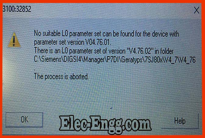
– What are your configuration version and device firmware version?
– If the error can not be reset it can be an indication of defective hardware even tho it is new. If you have changed any configuration Settings, try to upload the previous settings and check whether the error still exists or not.

elec-engg.com
https://protectionrelay.com/digsilent-training-package/
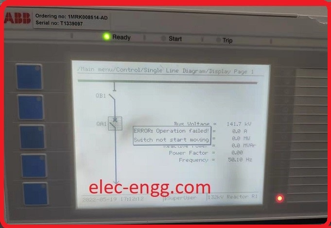
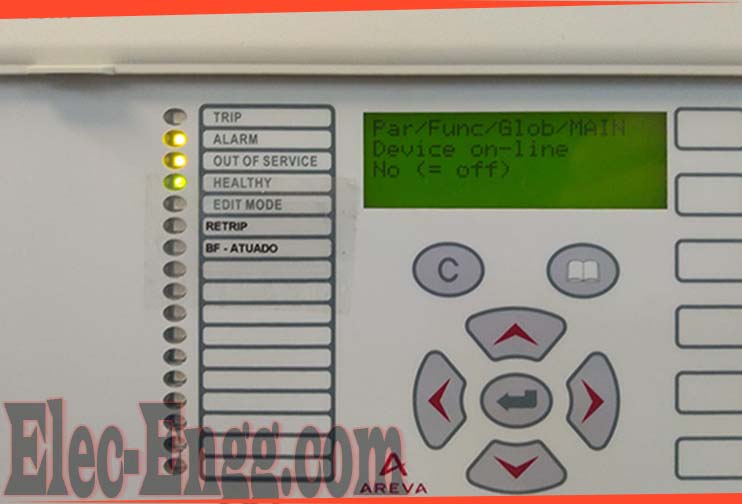
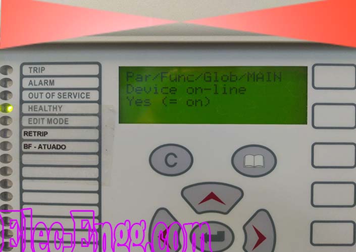
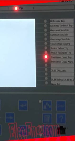
– What is the cause of the alarm as shown in the photo whenever I try to close BCU
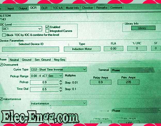
– Is this a voltage controlled over current? This means that your test plan needs to take into consideration both voltage and current variation.
For joining our discussion groups: https://elec-engg.com/whatsapp-group-for-protection-engineers/
– Device founds but was unable to connect. Digsi 5.
– Check your cable.
– Tried 2 cables.
It says 1 device found but doesn’t show the device.
– Check your driver for USB.
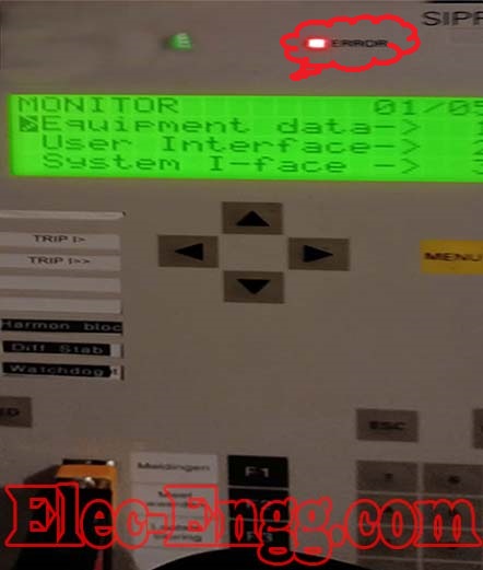
– I have performed a Siprotec4 7UT61 firmware update and now the device is in error mode. How to solve it?
– After you upload the firmware, you must initialize the device with the same version of the firmware that you installed.
– How to fix this problem while communicating with the relay?
– Driver Different firmware.
– When I copy one configuration file from one Siprotec relay and sent it to another relay in Scada, a feedback error came. I compared both files with two differences in the interface. One was an IP address and the other was a COM port
– My IP address changed but how could I change the com port number?
– How do change the com interface or any other thing that needs sorting out this issue?
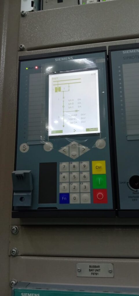
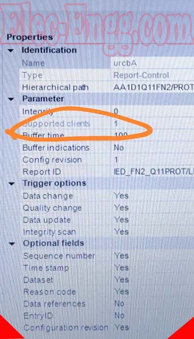
– In Siprotec 5 7UT I want to receive a command which is a single cmd, Which signal to use will show on display?
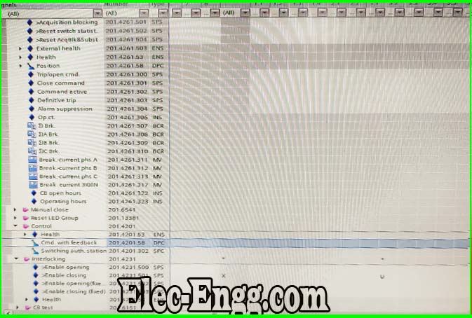
– Why DPC in BO is locked?
– layer 7 occupied “is resolved for the Siprotec relay.
– Anyone knows how to check measurements on Siemens Reyrolle 7SR5111? I can’t find any item to check, only on the relay screen.
– Check for instrument viewer.
– thanks, I tried, isn’t there any option inside the connected device to Avoid close programs executing “Instruments monitor?
– I can’t activate the 50BF trigger. Relay trip by overcurrent functions but breaker failure not working with 51 overcurrent functions. Maybe, only works with the 50 overcurrent functions? activation is conditioned to close switcher towards bus bar? After getting LBB initiation.
– Only it will operate. Otherwise, overcurrent will operate.
– Please check if LBB initiation BI is high or not. Check your 86 input is mapped to LBB initiation
– In which case, it appears 50 & 51? is not initiating 50BF. 50BF generally initiates a trip on relevant CBS backing up the CB in question.
– what is the LBB signal? An external trigger on a BI input? I have one but, only triggers 1 and 2 coil breakers, nor active 50BF function is not a transformer, is configured as a line. I have 86 functions configured. I have opened Delta core in PT should I directly connect to the relay or connect the loading resistor and then connect to the relay?
– Relay is 7UM62
– What protection function do you intend to drive with the delta core?
– 90℅ stators E/F
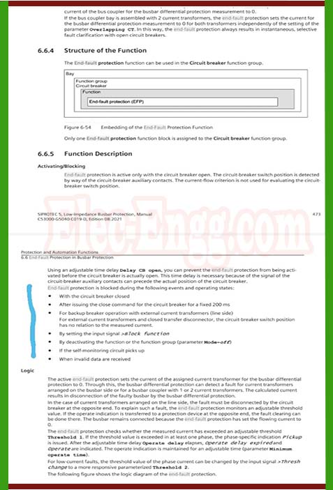
– In 7UT85 relay shows a differential blocked by an external fault and after 300 ms it enabled and tripped the differential.
For joining our discussion groups: https://elec-engg.com/whatsapp-group-for-protection-engineers/
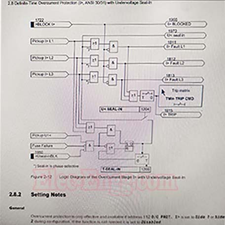
In this logic please explain the seal in the timer function.
– The Undervoltage value reaches to set value for T seal in time, at the same time I1 or I2 or I3 current reaches the set value = fault + t set time = trip. If my TI> is 3 sec and T seal in time is 4 sec then at what time the protection will operate?
– After T seal, in time Undervoltage resets itself. So in your question, it trips after 3 sec.
– I think both overcurrent and Undervoltage must exist for 4 sec (seal in time) then it trips. If voltage recovers before 4sec then it blocks.
Protection engineer user x: What I understood is:
a) If voltage restores before T seals in i.e, 4.0 sec then the protection gets blocked. And
b) If voltage doesn’t restore before 4.0 sec then will it trip if yes then after 3.0 sec?
– yes
– So the protection will operate at 7.0 sec…… TI> + Tseal in..?
– No it will operate in 3 sec I think
– It will check for voltage restoration I.e T seal in up to 4 Secs, right?
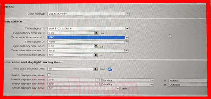
– It will count 4 secs to reset. If time zone time sources 1 &2 both are put local any problem?
– What is showing after again open, means it’s opening but the distance does not match with the relay display. Relay display showing crt distance.
– In the 415 V system, if an earth fault occurs in any outgoing feeder controlled through MCCB, then how earth fault protection will be taken care of? Any ideas or suggestions?
– In my system earth faults occured in one outgoing feeder which is controlled through MCCB and fuses. This EF, tripped my incomer and MCCB was not operated, nor fuse blown
– I have one doubt when there is an R phase fault is there voltage decreased in 3 phase for 20 ms but back to normal in un faulted phase what could be the reason?
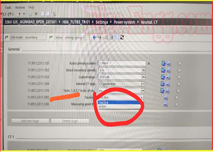
– Tracking keep active or inactive?
– Inactive
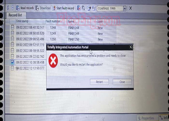
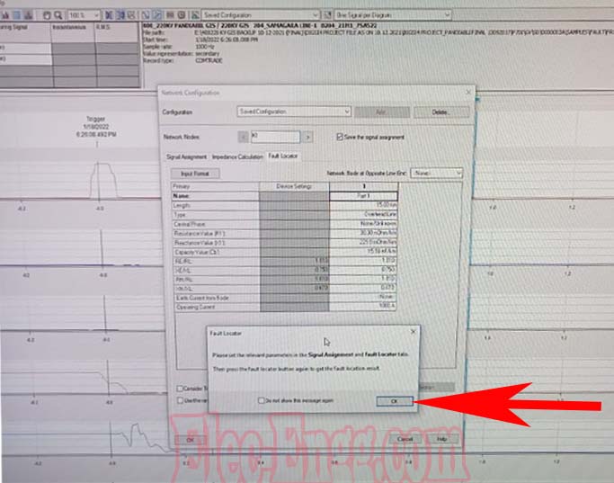
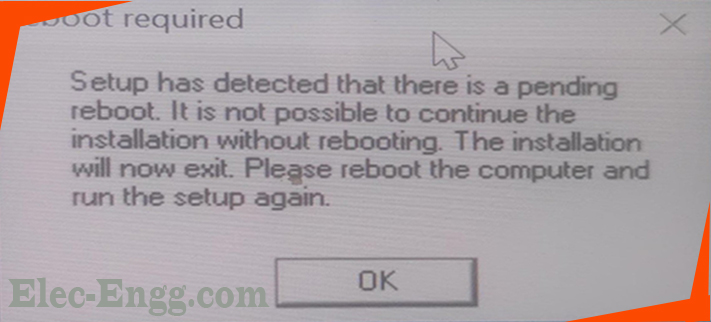
– I’m using digsi 5 v8.80. It’s working okay, but as I try to open or export any fault record in the online or offline window, this message pops up.
I have tried reinstalling the software, but the problem persists.
Any suggestions?
For joining our discussion groups: https://elec-engg.com/whatsapp-group-for-protection-engineers/
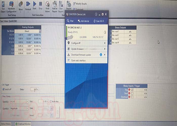
– why the msg of ENG074 could not activate the power supply after associating the omicron kit with software?
– Please recheck the ground supply. It will indicate when the grounding is not proper
– why the msg of ENG074 could not activate the power supply after associating the omicron kit with software?
– Please recheck the ground supply. It will indicate when the grounding is not proper.
– in relay siprotec 7sj 64 the protection TRIP 94 what does it mean??
– General Trip.
– Means to Trip Matrix.
– And what could be the cause?
– Any Trip condition, For any protection function
– External?
– Internal and external.
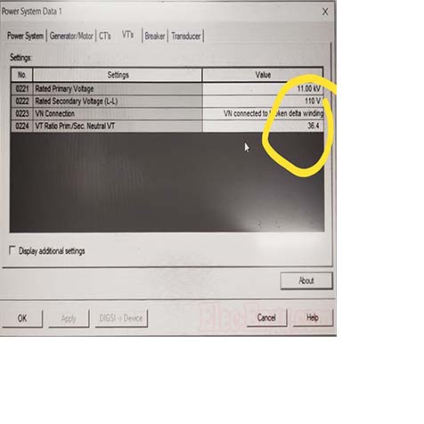
– B phase polarity is wrong. I think Angle must be -60 or 300
– Dir. Phase or Dir. EF?
– Nondirectional.
– What’s your Ref. Phase A?
– Yes
– A @ 0 Deg, B @ -120, C @ +120 should do the job.
– R and Y phase CT polarity to be changed then. You have said nothing about the CTs, so can’t comment.
– I just pointed out your voltage phase displacement. Also, you mention ABC & also RYB. Which one is it?
– RYB
– A and B’s current polarity might be wrong.
For joining our discussion groups: https://elec-engg.com/whatsapp-group-for-protection-engineers/

Elec-engg.com
– In the busbar protection manual close cmd is used for Binary input why use this?
– For end fault reset or too off
Micom p444 shows an error code while the relay is healthy. How to fix this problem??
– Reset the relay
– Yes make a reset of the relay
– I have restarted the relay but sometimes the same error is displayed on the screen.
– Read the relay’s manual and check what this error means
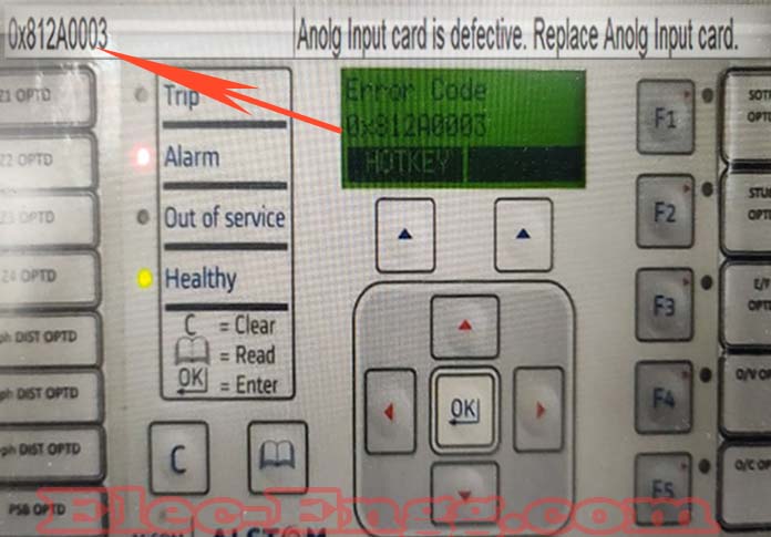
– As per the manual, the Analog input card is defective. It’s a distance relay right ?
– Distance relay gets CT and PT as analog inputs.
– Check if the relay is reading them okay.
– Unable to see parameters in the relay, it shows only an error.
– Then ask the vendor for a replacement. first, Check if your inputs are okay.
– In Generator VT, we are using an HRC fuse of around 120-ohm resistance at the HV side of VT (22 kv side). Can anybody tell me the exact use of the fuse and calculation parameters for deciding 120-ohm fuse resistance?
– I think resistance is not the deciding factor for fuse, we have observed 75-90 ohm also for 22kv generator VT, but the Fuse rating is 22kV,1A
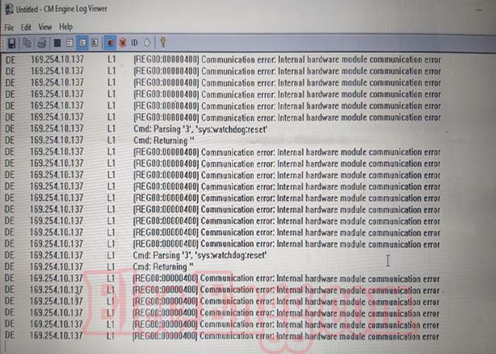
– The relay has frozen in this condition and has stopped communicating. How to do the general reset?
– Remove the supply for a few seconds and then give it back
– have you with Software between Relay and Computer communication?
I entered that parameter and it worked! unlocked
– But still, there was a communication failure
– I took the hardware of the source and put it again, then the communication worked normally
– When I am scanning, it gives an error, Relay is reg630 abb make
– Have you installed Hyperterminal?
-yes. I am using a crossover cable and the console cable. The hyperlink shows connected but it displays nothing. TCP/IP and telnet are working fine From the RJ45 ethernet port.
– Use converter USB tO rs232 And then scan again with your HyperTerminal
– Yes I am using it. Any hidden setting I am missing?
– No Settings to use HyperTerminal first bro. u just choose COM At the device manager
For joining our discussion groups: https://elec-engg.com/whatsapp-group-for-protection-engineers/
elec-engg.com
All Elec-Engg courses are available for you to take:
💠 DIGSI 4
💠 DIGSI 5
💠 IEC61850
💠 PSCAD
💠 ETAP
💠 PCM 600
💠 Micom
💠 Testing & Commissioning 🌐 Elec-Engg.com
For joining our discussion groups: https://elec-engg.com/whatsapp-group-for-protection-engineers/

elec-engg.com
Oil leakage near Buchholz relay flange. The gasket needs to be changed. what are all the tests to be done on the transformer if I drop the oil level and change the gasket in the 2.5MVA transformer?
– Dehydration test only And check the breakdown voltage of the oil. DGA test should be performed as per routine maintenance in order to know oil quality
– why did we put OLTC AVR in Manuel mode for the power gen transformer?
– Since OLTc is supposed to maintain. the voltage at the secondary side of Trafo and generator exciter is also set to maintain voltage. And Thus, Conflict will arise between 2 different types of equipment, if both will be in auto mode. Therefore, OLTC in power gen trafo is kept in manual mode and Generator exciter in voltage control mode.
– There IS a system like an AVR management system that coordinates between turbine generator, excitation system, and transformer OLTC. Gen Trafo OLTC is always operated manually (Means, human input). Turbine has no contribution to voltage control The excitation system is responsible for maintaining voltage on the secondary side of gen traf
– Replace the X120 card. You cannot on 615 replace the card yourself. It needs to go to the factory for repair.
– It’s possible to replace though you need to have the replacement card with you. I have done it several times
For joining our discussion groups: https://elec-engg.com/whatsapp-group-for-protection-engineers
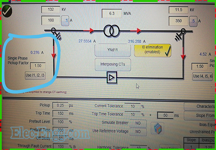
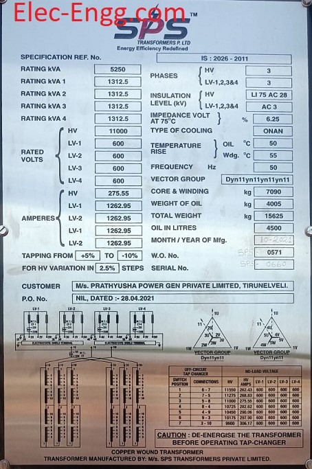
– What should be a single phase pick-up factor for the ABB RET650 differential relay?
– I rated current /I nominal current
– Aren’t rated and the nominal current the same thing?
– No. Rated current =S/root(3)*VLL. Nominal current is the primary current transformer ratio
– My bad. My rated current is 27.55 and my nominal current is 100, But when I try to test my relay pick-up, it does not pick
– I am asking about pick up factor
– Correction factor should be 3.623 at hv & 0.2212 on lv side…
– The vector group of my TF is Ynzn11, But the ABB relay only takes Y and D values. Primary CT is 100/1, Second CT is 350/1, TF rating 6.3MVA 132/11.5kV
– Nameplate selected 350/5
– Change W2
– Megger template does not accept values lower than 1. Do it by direct injection
– Can you tell me how you calculated 3.6? Relay is showing correct behavior on 3.623 HV side PU factor
– Display is not working how can I fix RET670?
– Check using the PCM 600 tool after a connection on the ethernet cable
– is the IED in an energized bay?
– Restart, if not come to life, then its OS is corrupted.
– Yes is on service now
– the problem is HMI fonts are corrupted. it is recommended to take out of service and fix the HMI font problems.
– I tried to switch off 10min and then restart again but the problem still persists
– Don’t worry, Check-in the PCM tool after going online. I think it may come from the protection function block.
– seems the IEDs are in an operational state, this you can check using many tools like PCM600 and IEDScout I but it is recommended to fix the HMI font issue in the relay LHMI for better performance and monitoring
– I tried to communicate with PCM600 but didn’t communicate with it. then you make the transformer out of service
-Transformer is in service now
– Did you enable IEC 61850 communication in this IED?
– Yes enabled
– Ok, is the ied reporting to the SCADA system now? Previous before this problem IEC61850 the status was ready
– What is the current status of the SCADA system?
– Can anyone send a connection diagram for this relay Ref615?
– Sss .. new version. In abb, website is still not updated
– Products will not be released to the market without the ied documentation release.
You need to properly check in abb medium voltage protection control ied sections
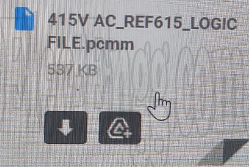
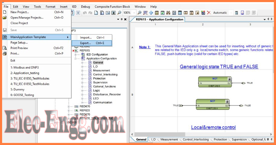
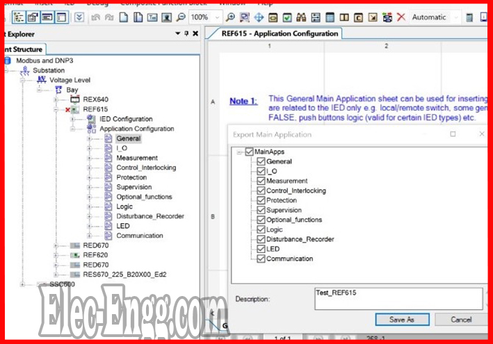
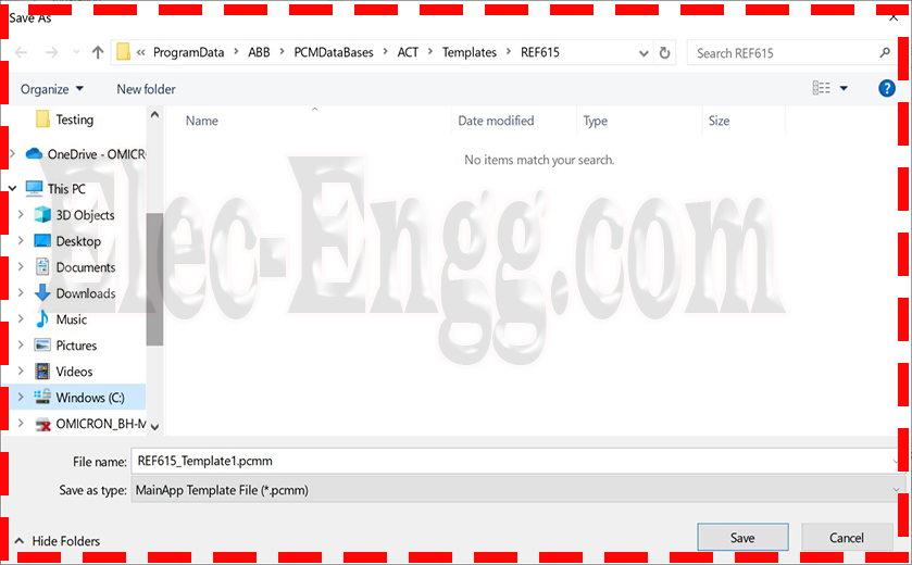
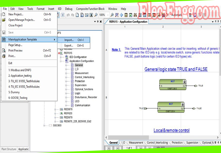
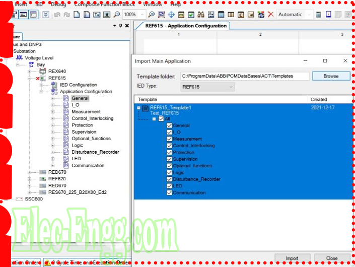
– I want to upload this file in REF615
– Pcmp is a project file. Pcmi is a pre-configured file from ABB
– But how do I convert this file to pcmi?
– Pcmm not sure if it is a configuration file, but if it creates a project, voltage level, bay and then imports that fil. If it cannot import then it is not IED
For joining our discussion groups: https://elec-engg.com/whatsapp-group-for-protection-engineers/
For joining our discussion groups: https://elec-engg.com/whatsapp-group-for-protection-engineers/
– how to disable DHCP On which model ied?
– getaway server all adapter, getaway SYS 9600C
– Basically, it’s a windows based pc on top of that Microscada software running on it. You can use the static IP address and check the status information by right-clicking the adapter that you want to know the DHCP status
– not disabled
– If you don’t want DHCP support just disable the DHCP service from the services
– I think if you configure IP manually, then DHCP is disabled. I have already checked sir same problem.
– What is the problem?
– DHCP should not affect if you give a static IP address
– Where are you connecting? What is your problem? It does not communicate with relays?
– It is 104 lines?
– yes sir
– Where are you connecting this adapter? To switch? Is this Master or Slave in 104?
– Slave
– And this goes through some router?
– Problem is that Master does not receive any information.
– What is sys 600c? Is it not gateway? Do you have some additional gateway?
– Can you show the architecture?
– Sys9600c getaway server
– I never heard of 9600c… only 600c MicroSCADA PC
– I don’t think your problem is DHCP but maybe the gateway is not configured
– Any other substations connected to these NDC masters?
– this is a new substation connected to NLDC’s newly
– And do you have settings for other substation gateways?
– In abb microscada, when giving the breaker isolator command in mimic it always shows the white color the color cannot be changed why? if you any suggestions kindly gives me.
– Check-in CET. Are the values properly updated there?
– only in mimic
– it’s not color changing
– value properly update sir
– what can I do now
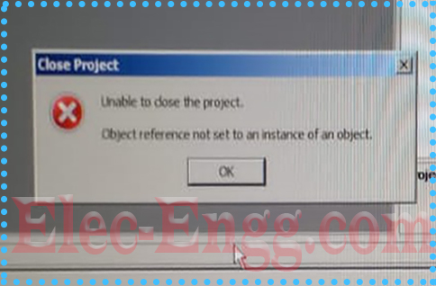
– Is the project empty? You will not lose any data?
– Open processes and kill the Pcm process
– Is the ied in normal mode or maintenance mode? From where did you download the ied modules if REL650?
– Maybe you are missing some files in the directory
– Check to add the REL650 ied object via offline mode and check the possibilities for the availability of the selection for different housing and display types to confirm the ied module instead properly and working fine on this pc.
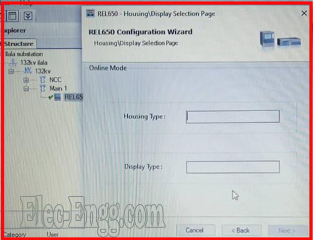
– Yes via offline mode
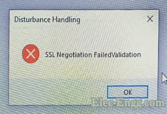
– I’m trying to read recordings information I’m getting a popup SMS above From REL650
– First, accept the certificate from the ied when you make the connection from PCM600 otherwise you will be rejected by the device. Accept the certificate permanently or for the session
– Close PCM600 and open again then make the operating to the ied, you will get a prompt to accept the certificate, do accept the certificate permanently on this pc in order to the device to make sure that you are using a trusted client.
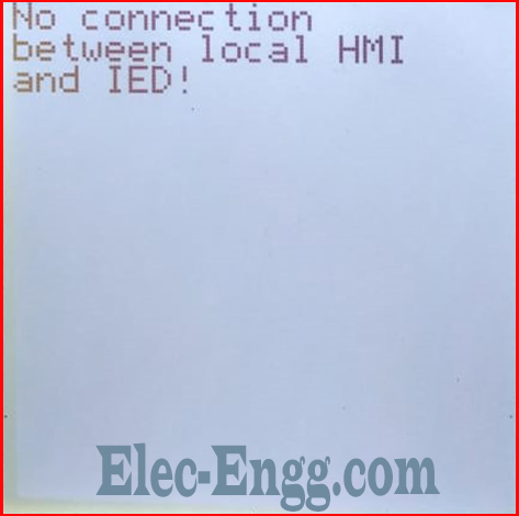
– ABB shows this message .what is the solution? It seems like an internal loose/open connection between the card & HMI.
– Check Ethernet connection between HMI and automaton
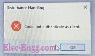
– It shows failed to install.. but the network has no issue… The Internet is working fine
– Disable the firewall and VPN connection if you use it. Try from other pc as well as different network
For joining our discussion groups: https://elec-engg.com/whatsapp-group-for-protection-engineers
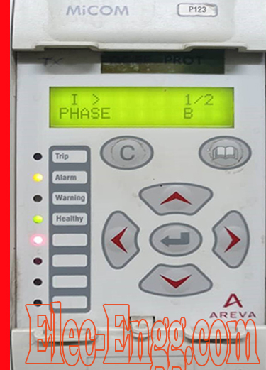
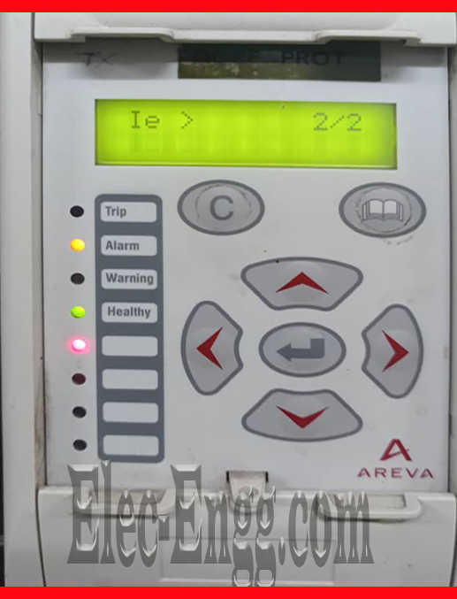
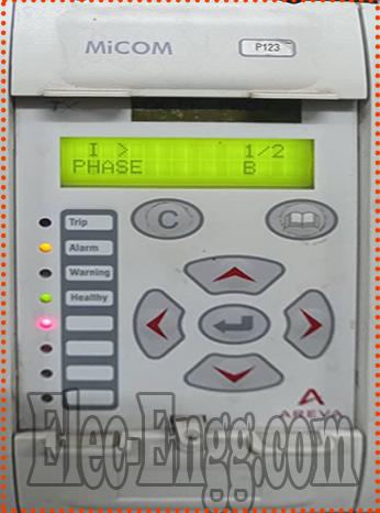
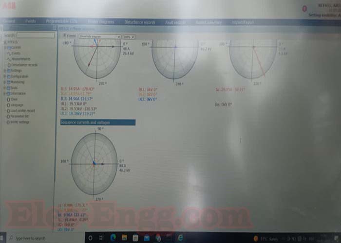
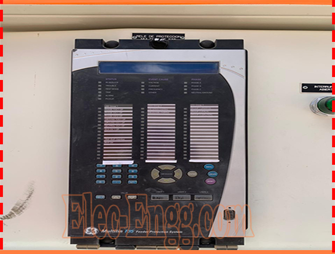
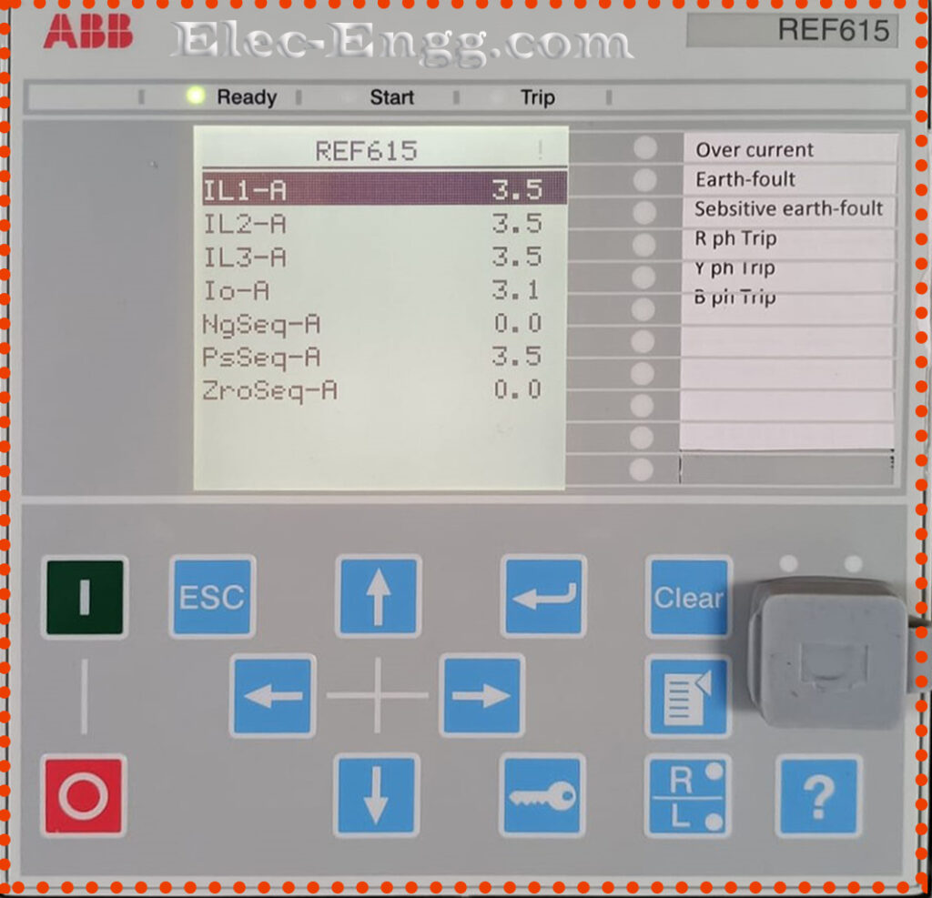
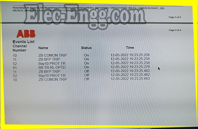
– Can someone help me with this fault? What it indicates
– indicates Over current in the B phase
– Indicates Earth fault in the first stage.
– We just trial energize a substation transformer but Deadshot
– First, check the protection setting and IR resistance of the transformer with cable or bus bar
– What about retrieved events?
– Those events should be carefully checked
– Will revert back to you once I carry out this
– how to configure goose signal from siemens to RED670 relay? please ping me if any documents are available
– In Digsi use IEC 61850 configurator, import RED670 .cid and route signals as normally used with any other Siemens relay. All internal signals and configuration in each relay must be made first before exporting .cid files
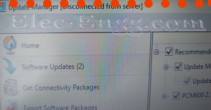
– why disconnected?
– many reasons, for not having the latest Update Manager version and not having the high-speed internet
firewall blocking, proxy settings issue
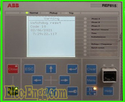
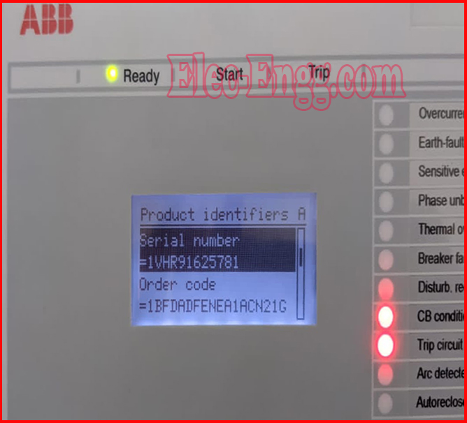
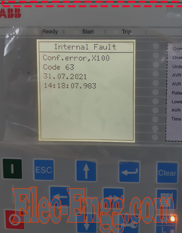
– why this REF615 relay is going to fail? In one day it restarted approximately 25 times and this alarm appears. Is there a solution or is replacement recommended?
– It’s a software error, speak to ABB
Protection engineer user x: Clear this warning and check the IED SOE(Sequence of events)internal events from PCM600 why the ied is rebooting automatically?
– May we not get the proper auxiliary voltage power supply (fluctuations)
-Why it is happening? What is a recent change that happened in this relay?
– Check the healthiness of the power supply source, power supply module, watchdog contacts, and configurations
– Check all these details properly if you observe everything is ok. You can still do that firmware update by yourself easily by taking ied out of service if it belongs to the energized feeder.
– Ok I will check the events with the software, and I will check the auxiliary voltage level, however, I do not think this is the case since there are 14 relays connected to the same voltage source and only this one is the one that presents the fault.
– Recently technical staff have downloaded a new PCM600 configuration for all relays
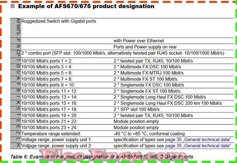
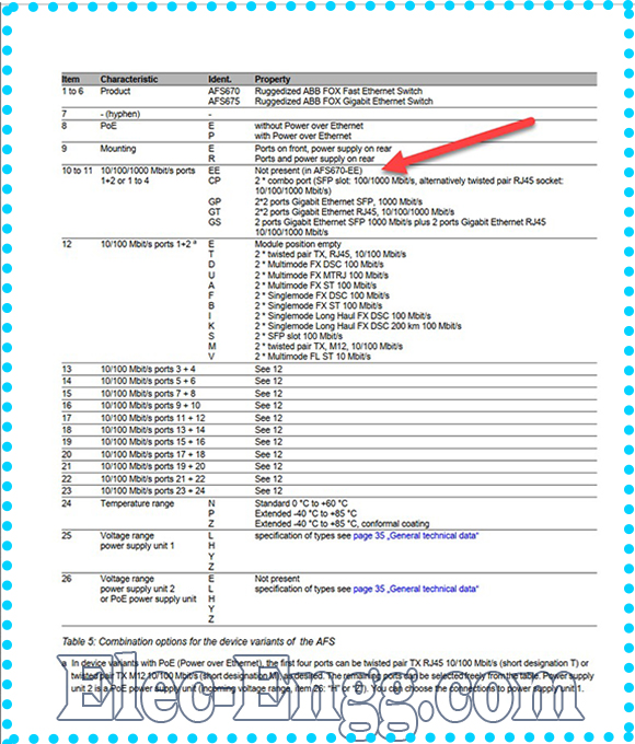
– Is it possible to connect the RJ45 cable to the SFP port in the AFS670 ethernet switch? If so how?
– If the AFS670 is having flexible empty slots for SFP support(from the order options)then you can able to do that. if your switch model number is having support for that particular option then you can do it.
check out this and compare
For joining our discussion groups: https://elec-engg.com/whatsapp-group-for-protection-engineers/
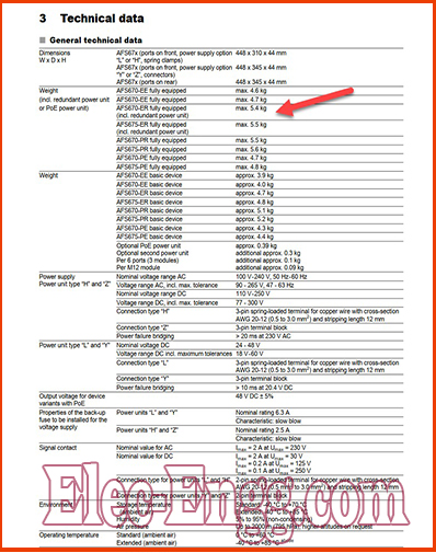
– In my case, there are 5 empty SFP slots but need to accommodate 5 RJ45 cables.
– Can you please share this manual with me, I couldn’t find it on the Internet
– you send your order option picture of the AFS. may be to me personally so that you avoid some problems related to MAC and other details in the picture in the public

– How to log in micom c264? Because I logoff to make some changes On relay parameters
– User name: Engineer
Password: AAAAAAAA
This is for Schneider to make C264
– Without FO cable connection is it possible to test Line differential protection?
– no
– In this relay. For any fault the PO1 PO2 is not getting NC due to this the breaker is not tripped so please suggest solving the problem
– Now we are testing line differential RED 670 without FO by switching off CH1 &CH2
– Check application config. in PCM. It needs to be configured
– PO1 is Close command and PO2 is Breaker Failure Backup Trip. You need to check circuit diagrams and configure input and outputs accordingly
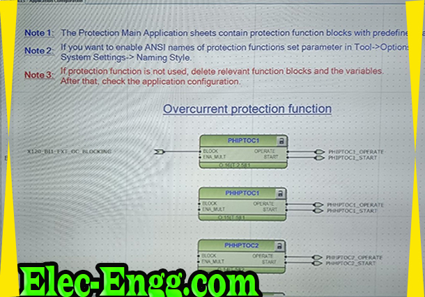
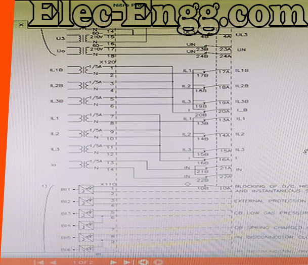
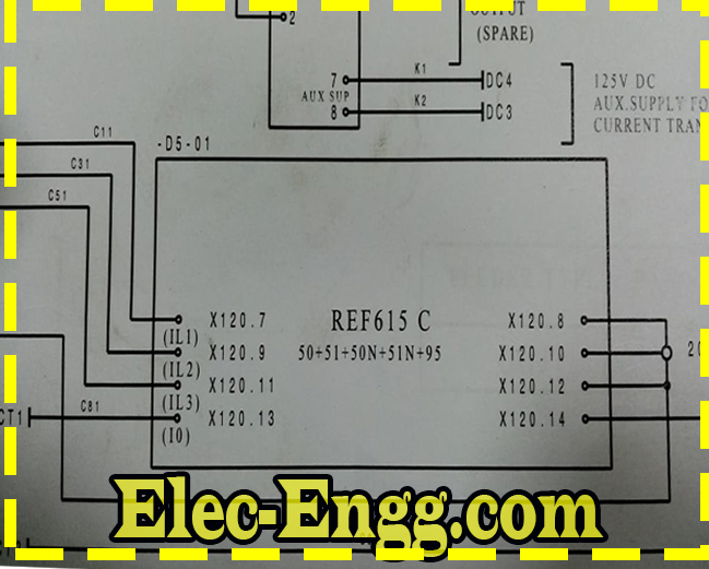
– What is the function of X120 BI1 EXT OC BLOCKING? To this, we have to connect the circuit breaker close feedback
– Typically that would be used for “logical” busbar protection
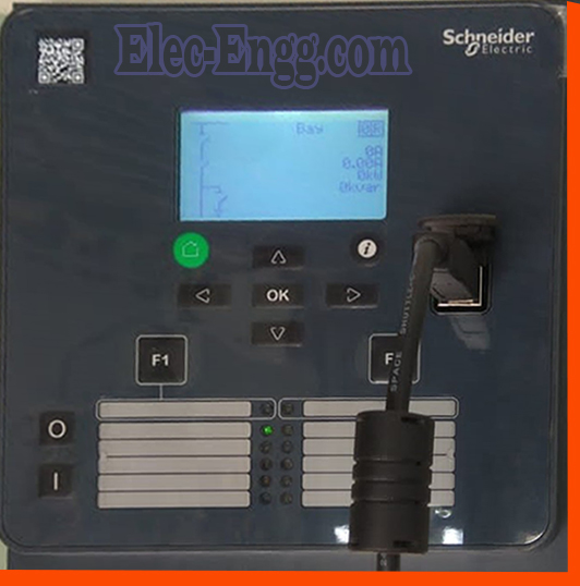
– Can anyone inform me if is there any license required for the EcoSui software of Schneider Electric?
– Yes, you need it for long-term use By default, you can use it for 30 days as a trial later you need a license to run the software.
– Is there any license required for DS Agile?
– No, not required
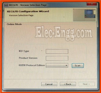
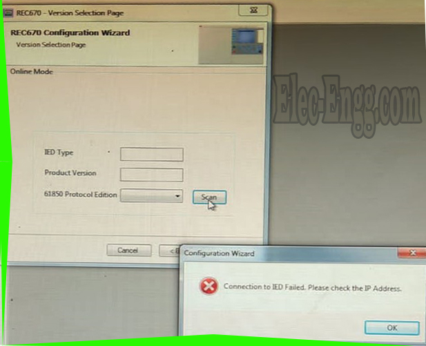
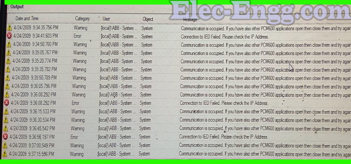
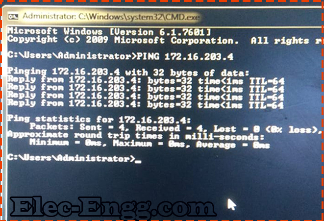
– Do you have physical communication to relay? Can you ping it from the command prompt?
– Is the IP address correct?
– Close PCM, re-open it and open only 1 IED
– All cleared… Right-click on Bay name and Add IED, choose the correct version
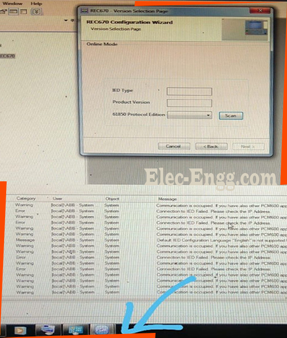
Hey, you opened the same project two times. the connection is occupied from PCM600 to ied from the other PCM600 instance. Close the instance and work with one to the online ied. Use the pre-configured pcmi files from the update manager
* Take them from the Update manager.. they are all available there… Al templates
– I am required to submit the relay settings. If the .pcmi files are available with you, please can you share them?
– Do you have PCM?
-Then use the update manager which you have and download whatever you need
– I can download the data model of the relay from the update manager. But cannot define the settings without the .pcmi backup file.
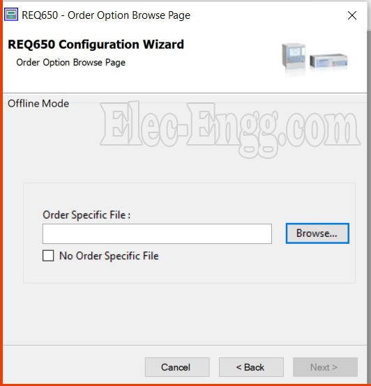
– use templates to create the relay you need. Click no order specific and make any relay you need. You need to enable advanced options and the type of pre-configuration template (IEC/ANSI) in the settings menu of the update manager in order to see the pre-configured files in the update manager
– I can select the no order specific option and proceed. But cannot really enter the settings. The settings tab will be disabled.
– Read the engineering manual. Because there are no functions in… You need relay configuration which will actually be used
– You need to add the mandatory hardware modules from HWT and go for the ACT and customize the functions (add and map) that you added in the act from PST. This is the starting workflow.
Read the engineering manual it is also available from the update manager for free
For joining our discussion groups: https://elec-engg.com/whatsapp-group-for-protection-engineers/
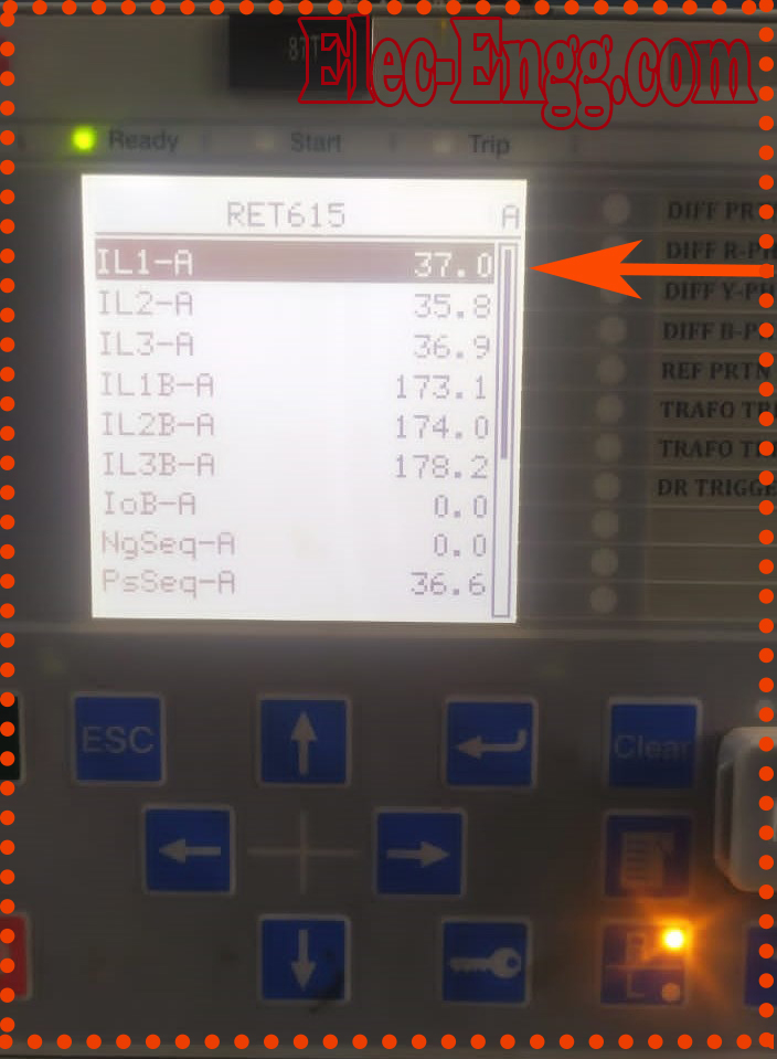
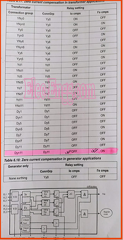
– In ret 615 x120 ct connection terminal 1 2 3 4 and 5 6 is lv or hv ct point? Current is not matched on hv and lv hc CT ratio is 300/1 and lv ct ratio is 900/1
– Tr is 16.6MvA 33/11 kv, Dyn11 Once check parameters of transformer datails in relay settings
– Wt about the difference in current?
– 1.5 times low in actual current hv side
– Getting root 3 times more But check the parameters
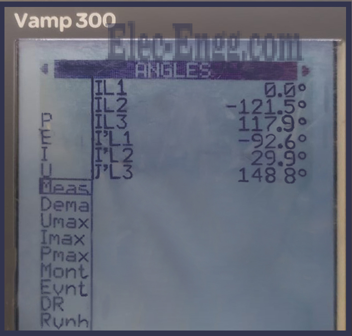
– Why phase difference is a mismatch in r and y phase in differential relay transformer is dyn11 vector group
– voltage is there? sometimes u need to have voltages available or sometimes u need to make a reference which phase will be a reference for the other 2 phases
– No available voltage in there
– check settings inside the relay
– Setting is ok I think polarity is a mistake or not
– check sequence also
– In this related to T terminal point is lv or HV bct connection point
– HV side is ok but the lv side should be balanced by -150, 90, and -30. Verify vector group selection in relay & physical polarity.
– Vector group selection in ok
– If relay tested by secondary injection then check field connections
– Also Check CT swapping is normal or not in the relay.
– Transformer is tripped when the differential setting is on
– This condition not getting satisfy so it is getting trip.
– How ct is swapping
– Is there interposing scheme?
– Is there a High impedance scheme?
– Does anyone have ABB test report FORMAT for relay model NI 41?
– hello anyone with a commissioning protocol for a new circuit breaker
– The fault analysis app it’s seems to be good
For joining our discussion groups: https://elec-engg.com/whatsapp-group-for-protection-engineers/
– How can I inject from the relay back side, relay side 221, 222, 223, 224
– It should be 1200
– I inject from x120: 7,9,11,13 And 8,10,12,13 short connect to neutral
– Inject from 221 L1 ,222L2 ,223 L3 ,227N.The link between 224,225,226,227 should be open
Check injected current value by clam meter
– Please check the injected current phase angle it should be 0,120,240
– Correct
– I tried the exact measurements coming
– Why phase difference is a mismatch in r and y phase in differential relay transformer is dyn11 vector group
– voltage is there?
– sometimes u need to have voltages available or sometimes u need to make a reference which phase will be a reference for the other 2 phases
– No available voltage in there
– check settings inside the relay
– Setting is ok I think polarity is a mistake or not
– check sequence also
– In this related T terminal point is lv or HV bct connection point
-HV side is ok but lv side should be balanced by -150, 90, and -30. Verify vector group selection in relay & physical polarity.
– Vector group selection is okay. If the relay is tested by secondary injection then check field connections
– Also Check whether CT swapping is normal or not in the relay.
– Transformer is tripped when the differential setting is on
– This condition not getting satisfy so it is getting trip…
– Give the connection as per definitely it Will work
7 to r
9 to y
11 to b
13 to neutral, And connect the loop cable to 8,10,12,14.
– I tried this connection not coming. Otherwise, cts may be an error in the relay
– Can we solve it Or send it to the factory?
– Once give the 0.5 amp between individually 7 to 8
9 to 10
11 to 12
13 to 14
Then check the error how much it is
– Once confirm it, If a huge error you have to send it
🔻our courses: DIGSI 4 & 5, PSCAD, ETAP, ABB PCM600, IEC61850, Micom, Testing & commissioning, Generator protection, DigSILENT🔺
Elec-engg.com
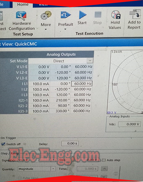
– Why do you have 0 -> 210 shift for the first phase?
-In quick CMC, R-0
y-240, B-120 FOR HV SIDE, And then add 30, R 210 and y, b is the balance angle, the Phase shift of 30
– By setting 110 % injection voltage is 73. But when I injected nominal voltage over Flux operated
– When I inject above 70 its reseted
– Firstly note down all settings perfectly and check each protection remaining in the off condition
– I measured the voltage from the relay it’s not reaching the injection +
– Once check with a multimeter relay and test kit
– I measured the kit output it’s got the Exact value
– Maybe the phase angle not getting properly In relay get different phase angles s
– What about a relay And did you connect directly?
– Check the Phase angle
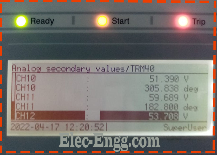
-180, 300 & last one not showing
– First normal voltage give and check values in the 3relay are the same or different.
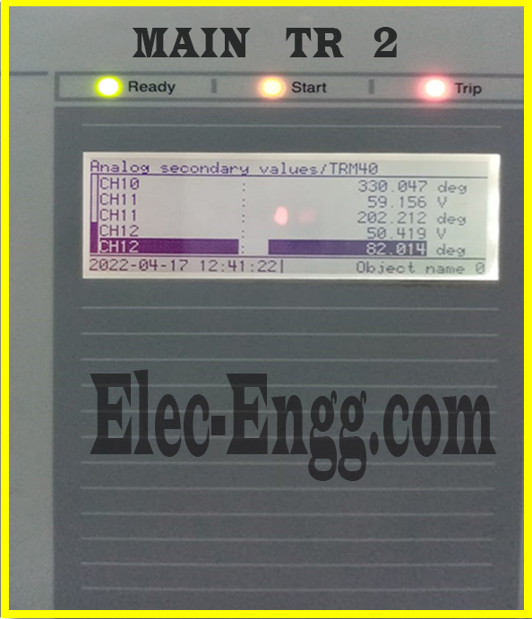
– This is my nominal voltage. I am receiving this voltage
– How about nominal Hz?
– 60hz
– Protection user x: Is it possible to get any vacancy in Telangana in the Electrical stream
– Any have settings for generator p40 agile micom type p343
Relay testing
– When the protection coordination fails within a DER between the DER relay (recloser) protection and the Substation recloser, the CTI (Coordination Time Intervals) is below 0,2 sec.
Can anyone share the different mitigations (methodology) we can apply to fix this issue? I will appreciate any book, any training video, excel sheet, or an example.
– Is it DAR or DER?
– Whats DER
– DER means Distributed Energy Resources or microgrid. But the problem can be generalized to any distribution coordination study. How do we fix falling time coordination between two consecutive relays? Any methodology to follow than the trial and error approach?
– Are these outdoor AR or they are actual IED relays with AR function?
– Your question is a bit general what’s installed on your network? What protection function is initiating the AUto Reclosing?
– Can anyone please tell me how to test open delta protection?
– Once could you send a wiring diagram of open and other VT connections? You can apply the voltage protection relay and test at open delta PT input terminal to relay, normal operation this voltage will be zero, during fault voltage will be present in open delta PT output, hence you can apply slight voltage to terminals and check, depends on your setting it is an act
Protection engineer user x: That means I have applied voltage into 3 ph VT core and I have checked in the open delta VT core?
– you can do a second injection to relay. if you want primary injection then with the less unbalanced voltage you can test it
– Is it open delta depending on other star-connected phase angle deviation
– voltages which create to flow the voltage in open delta
– Then I have to just inject the fault voltage in an open delta circuit for testing?
– depends on your setting and VT ratio in the relay
– Thank you, I will try it. Are there any other things I need to take care of while testing?
– nothing, apply voltage shouldn’t be more, be sure about that
– Why don’t you take from Update manager? It’s not coming to REG 615 D, But Reg 615 and 615 A and REG 615 C it’s shown
For joining our discussion groups: https://elec-engg.com/whatsapp-group-for-protection-engineers/
– start SQL Server From here:
- Widows Task manager, Service Tap,
- Install the latest version of PCM600 2.11 and you get the SQLServer 2019 support that works better than the previous versions
- Find SQL Server, in the “Status” tab, set in “Running”.
- Uninstall this old version completely first
- Try the latest version for better performance
Well noted let me try the latest version, It’s giving me the same error code
– Please show the full message of PCM
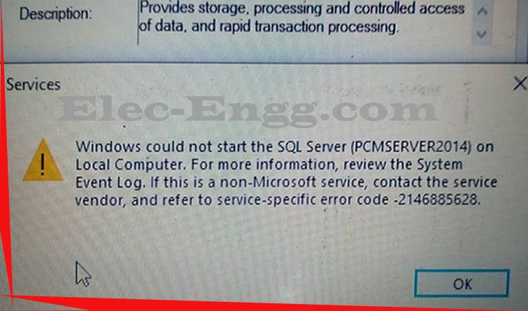
– Remove the PCM600 SQL server instance completely by uninstalling it properly
– have tried but same error. hoping to install version 2.11
– try starting from the task manager
– Have done it but the same error
– same error
– Restart your computer and try to open it after 4-5 minutes. Or you can type services.msc on Run and manually start SQL Server (PCMSERVER) after finding it.
-Tried and still no luck
– Did you install updated Microsoft Visual C++ redistributable packages? If yes then ok. Otherwise, you can try with an updated version.
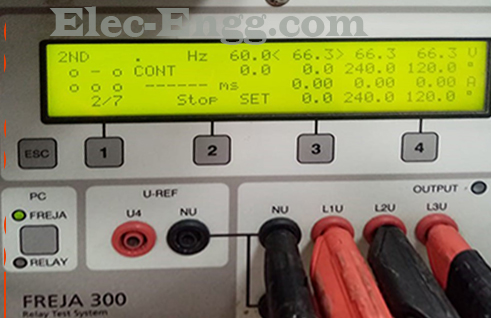
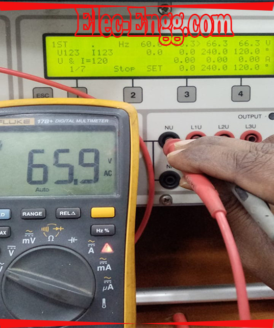
– What is the phase angle we have to inject for synch relay?
– It’s both should have the same voltages with the same phase angle
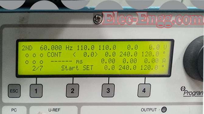
– See I inject the set value but relay not responding
– First keep the time knob minimal
– V1 and V2 give the 63.5 voltage with the same phase angle
– Slightly change the phase angle then once check it
– But my voltage settings are 110v
For joining our discussion groups: https://elec-engg.com/whatsapp-group-for-protection-engineers/
– how is this TCS implemented in bay control rec 650 and REL 650, what I see is it’s active when am decommissioning old breaker. am failing to figure out how they implemented it
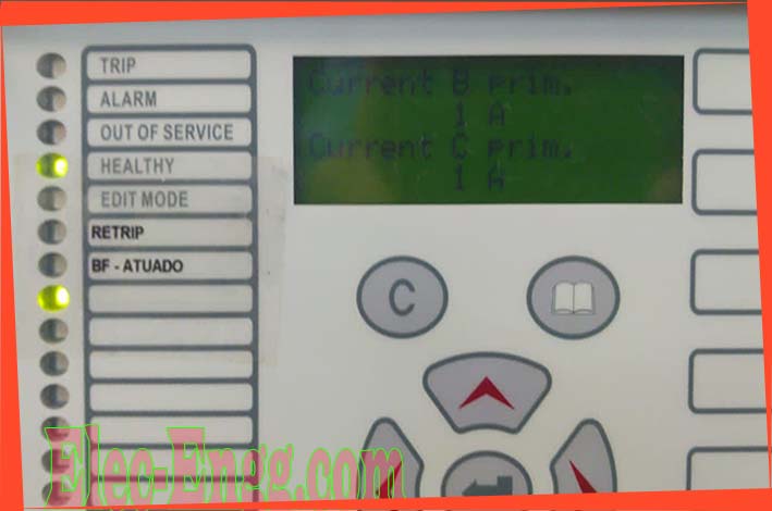
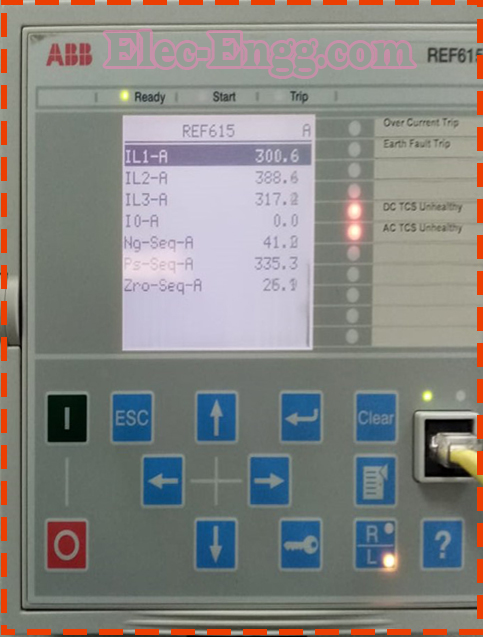
– In this relay. In no load condition, the amps are showing. Please guide me
– You should check the configuration on the relay related to measuring Io or the analog circuit to transformation into Io
– What’s your problem?
– I have an abb 530 series CM module have 2 ethernet ports. but I am able to add in hardware tree (rtu util) for IEC 61850
– You should check the support protocol for ABB 530. Which is your RTUTil version? It supports the protocol. but only one port i am able to. You have to add more CM or use another protocol 104
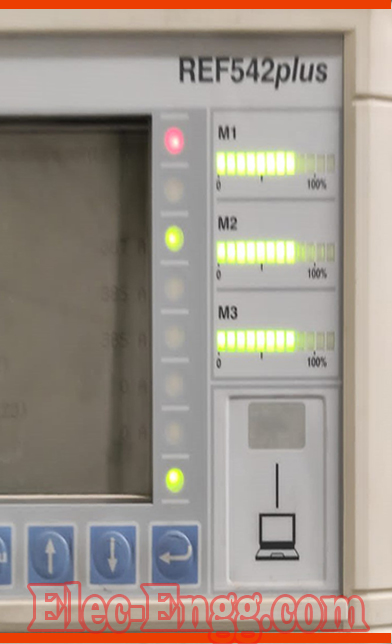
– Pu30 relay communication problems
– Schneider Electric
– Why not com port showing?
– Contact Schneider customer service
– Instal USB drivers from the Schneider website
– if not my mistake, this relay should use vampset driver to communicate to pc
– Modbus scan I am getting this message, It’s connected
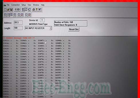
– Modbus timeout
– What can be the reason? Device not connected
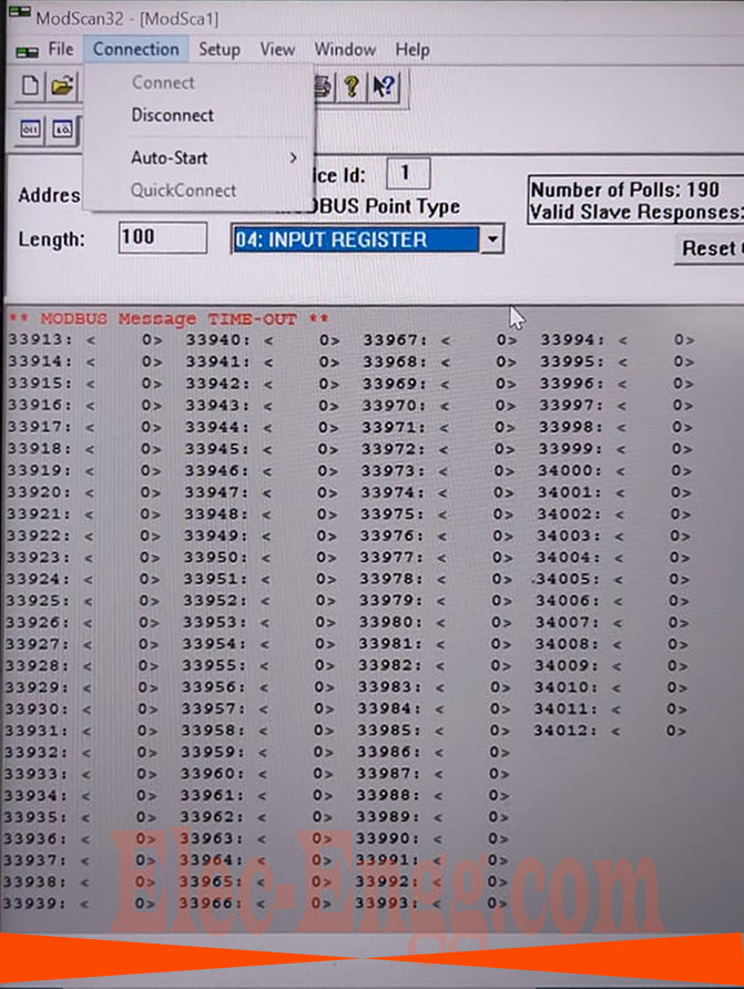
– It shows connected
Protection user x: what causes a single pole breaker to trip immediately after it closed yet all positions status are okay
– Is it all DC supply in off
– the dc is okay and after it’s closed the TCS alarm is not appearing at all
– what could be the problem? of circuit breaker single pole CB that, after wiring, it can do all controls well open and close and when I make close command all operations work every good when am at the MK, after in make wiring for TCS, the alarm clear on the panels for TCS FAIL but When I make a close command it trips after closing
– trip Lockout still latching
– breaker first completes the closing cycle then it trips. maybe CB Pole Discrepancy read any CB Status not correctly for CB Closed
– all the CB statuses are well addressed, but the TCS seems to be tripping it. Maybe current from TCS is enough to trip the breaker
– Hello, I have this error on my relay micom p444: error code 0x81170000, what I Can do
– Co-Processor card is defective. A coprocessor card is used for distance fault location/calculation.
If you have a spare relay you can just replace the co-processor card, just inform the manufacturer they will guide you on how to replace it by taking a bay outage and doing the replacement safely.
If you don’t have spare contact manufacturer they will arrange a spare/healthy co-processor card for the required model number

Elec-Engg.com
For joining our discussion groups: https://elec-engg.com/whatsapp-group-for-protection-engineers/