

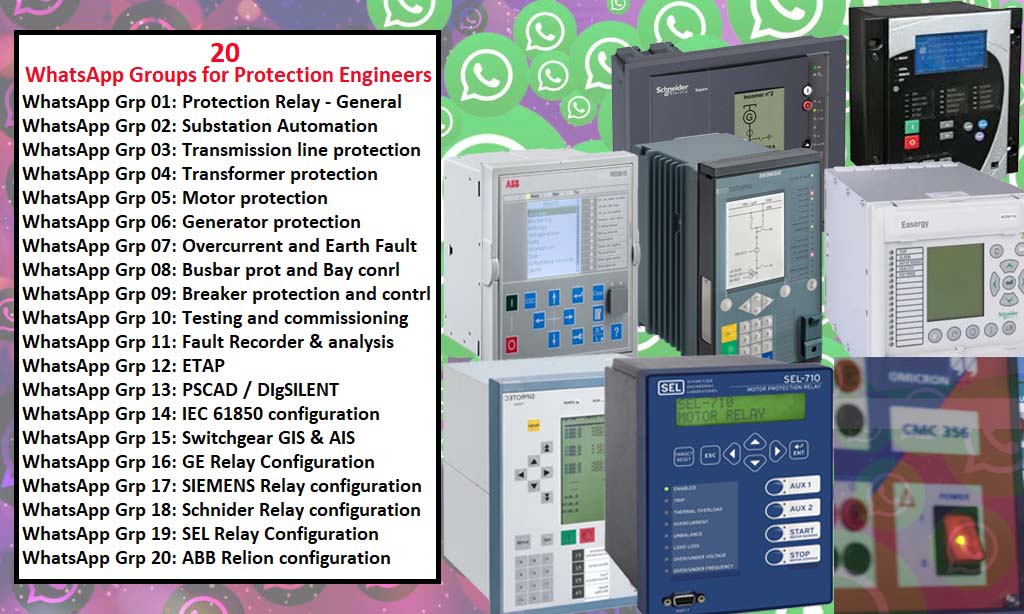
Join our protection relay WhatsApp groups
– Does the CT ratio setting in the relay already correct? Does secondary CT connect properly?
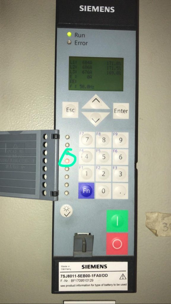
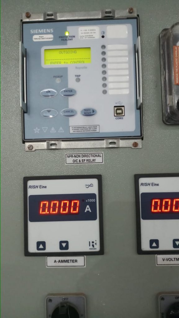
– The amperes showing at analog meter are correct.
– Your relay reading is not correct, and your Ip shall be the same as I>. Make sure that I am in the secondary setting
– How do I make it secondary? Isn’t it pre-defined in the device?
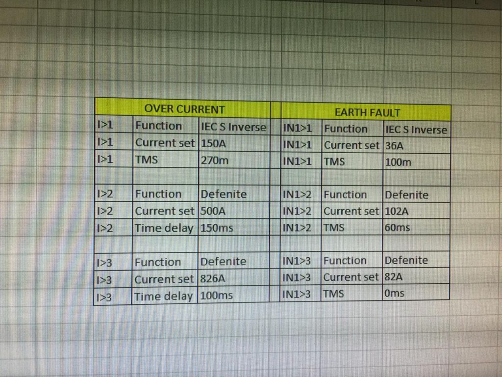
– I think following my setting is better, and what is your Transformer capacity?
– 20/26MVA
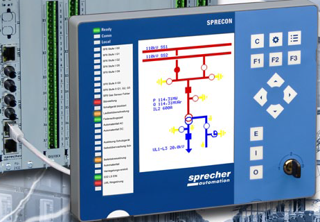
– Incoming
– Don’t know about Z
– Outgoing
– I think you better check the setting with other outgoing feeders and make the same value as those feeders, is the best solution
– Combined load is on this feeder Other settings are the same as it is.
– you know setting the protective Relay is not just putting the value but understanding the network with a single line diagram with experience of tripping.
– Before playing with the tripping setting Please make sure the meter of the relay should be correct. 1st to know is a single line diagram of the network. 2nd is the upstream value to make good coordination. 3rd is to understand the setting value. You go to System day for outing the primary or secondary parameters System setting.
– please how do I change the time delay setting on an ABB RET670? It’s currently on definite time but I want to change it to IDMT.
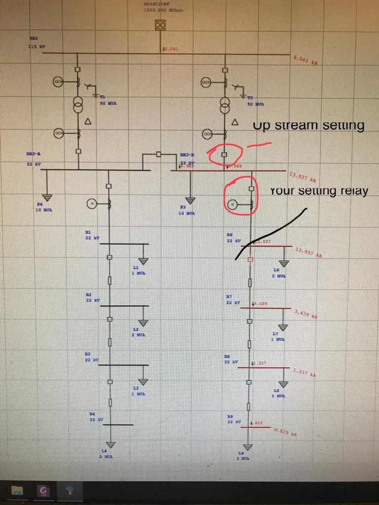
– Sir I checked the SLD what is the upstream value? From where I search/set that value.
It indicated 4th (indication) System was overloaded.
– As I know Your upstream setting is the setting in the incoming feeder (do you know that?) then check the Relay at that incoming feeder. Because your setting feeder is the outgoing feeder.
– We haven’t this software to draw SLD
– How can I know that?
– Show me your SLD I will tell you where is your upstream
– I will send u by handmade SLD (very simple) Coz I don’t have the software. Yes, just simply no need for software. Before make setting a lease you need SLD from your utility. If you are just the first time in setting Relay, you need to learn more. Does anyone know the Three-phase Energy measurement setting in REC670 Relay? Energy is not increasing with the hour in REC 670 measurement. I am testing communication between the Central unit and bay unit, 7SS52xx bus bar prt relays, I am not been able to set up the communication.
join our protection relay WhatsApp groups: https://elec-engg.com/whatsapp-group-for-protection-engineers/
– Anyone has exposure to Schneider ecostruxure?
– I am led to believe that relay interrogations are reserved for essential and critical services, eg. hospitals, frozen foods packaging, etc. Nonessential and all-new project-related activities (unless critical) have been dropped. Have to Implement it?
– We already had remote interrogation capabilities for all relays on the network via respective software SEL AcSELerator, exercise, DIGSI4, etc. during normal operations. It’s now a bit more stringent and reserved only for circuits deemed critical/essential.
– ~exercise~ enervista
– By using LAN?
– So your relay already has the IP address, which has been regulated by your team?
– WAN. Wide Area Network. But I won’t be able to do well too deep on this.
– How about the security issue? Maybe cyberattack? What is your mitigation?
– Now we are getting a bit deeper, and into areas which I think I won’t be able to comment on for obvious reasons.
All I am allowed to say is there are firewalls in place, to say the least. All commands sent over the network are encrypted.
– How to create Zone in distance relay Micom P543?
– It is ready to use on the relay. Take a look at the software S and you will see that it’s very simple to set it. Unfortunately, I do not have it here.
– Plz share the manual & video if possible.
– Go to Schneider site nas download the software S. It is free.
– is there any way I can get to access records of webinars already held (records or archives)?
There was one that was held between 9th Apr & 14th Apr which I missed and would like to see. Thanks in advance for your help.
– Why generator differential protection is percentage-wise?
-To add stability for external faults and CT saturation errors.
– In the relay, we have two coils. one is restained coil and one more operating coil
– The low impedance relay will work according to the above principle
– there’s one question that what impacts the life of CB more? high-intensity faults or more number of operations under faults, over a span of saying few years?
– Because the relay stages are set to certain calculated percentages i.e stage 1 is 15% stage 2 or high stage set to 70% etc.
– What is I^2t protection LSIG? what will be the impact?
– Thermal overload. its thermal overload protection, LSIG stands for long short, instantaneous, and ground fault characteristics
– there is an option in I^2t protection on/off. if on means what will be the impact?
– what is the application? and which relay? is it feeder protection?
– For motor protection only we need to enable this I^2 t. correct?
– LV motor?
– thermal overload is used in all protection generators, transformers, transmission lines also in motors.
– Its CB inbuilt micrologic 6.0
– Masterpact Schneider right? What is the rated power?
– 5K
– if this breaker is used as an incomer in the Motor control center or LV distribution board, there is no need to enable this.
-in an individual application, ie breaker delicately use for motor switching, it’s better on this function and checks for the applicable char with motor manual, If the breaker used for UPS power up?
– Think so, i2t on – will follow IDMT char and off will follow DMT char, Even I2t – on enabled and fault current more than 10 times then will follow DMT rather than IDMT.
– What type of protections are used for phase-shifting Transformers?
– In normal Transformers, we have vector group compensation. Since the vector of phase-shifting Transformers keeps changing, how do we employ differential protection for it?
– I mean, phase angle keeps changing in PST as per transmission requirement. Vector group will not change
– can anyone help me to discuss the ferroresonance that may occur to medium voltage potential transformer?
– It’s a stochastic phenomenon that occurs ultimately results in the destruction of potential transformers (particularly wound type), it doesn’t matter if it is low, medium, or high voltage.
– what do you mean by stochastic? Does it have no rule?
-Stochastic in this context means, just because the conditions are favorable for ferroresonance to occur, there is no guarantee that it will occur and vice versa, which is what makes it one of the most dreaded electrical phenomenon, a headache for electrical engineers.
– can you support me with a technical guide for this phenomenon and how to protect VT from it?
– You need damping resistors on star or delta connections?
– What is your system grounding?
– grounding through low resistance
– It should be connected across the broken delta
– if I have not to Make a broken Delta connection of VT and connect the damping resistor, If not size the suitable resistor and connect it in star fashion
– two resistors in the series are shown. If you have the correct resistor rating, you can connect a single resistor
– what about the VT burden? How does equipment in a substation works? Such as circuit breaker, battery charger, protection relay & switchgear. And how are they related
– Ya it relay is connected to 11kv v.c.b And it is controlling the total reducing power of a feeder
– When the feeder capacity has gone high then the relly is not support
– Then the current is going 73amp, the system has gone trip how can I increase amp value?
– You have to size the resistor so that VT does not get overloaded
– Generally less than 50%
– I want to know how to increase load capacity in the relay? Because the feeder stops as soon as the load in the feeder is high. What do you mean feeder stops?
– How to set up in Rally when we have to give more load
– first things first, please frame your questions properly.
– I can’t speak for others, but I am finding it very difficult in understanding what it is you’re seeking.
You want the relay to not operate when more current is going through the feeder. Is that correct?
– How to increase current carrying capacity in the relay?
– You can not increase the current-carrying capacity in the relay. What you need to do is to increase your pick-up setting.
– What characteristic curve are you using?
– 100/200/400.
– That is the CT primary ratio you have mentioned. A characteristic curve will be given by the motor manufacturer. Usually, C type or so, plz check in the relay.
– you need to read your relay manual. Please read up on what a SI curve is to start with.
It- Not clear, but I think it’s a SIEMENS Argus 7sr which you’ll find on their website.
– always make it a point to type slowly and try doing a spell check please, that way you will always command respect from your peers especially in a group like this where you have people from all over the world.
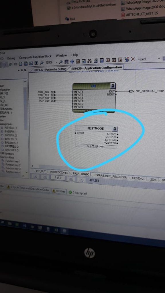
– Someone knows how to connect this block?
– U can activate that test mode block by the connection of a TRUE signal to the Input. Detailed procedure is available in the manual (Pg. 117-120)and also in the attached image
Hi all, I am trying to check if I can automatically import MHO characteristic graph in the omicron test object via the XRIO file for a P445 Relay?
-Why don’t the LEDs on the top light up?
– Have you imported the respective relay filter for that?
– Sorted now, I used the PTL template and used the import relay settings option instead of just the import option. All graphs showing now.
– with this standard: IEEE Std C37.112-1996 (R2007), IEEE Standard Inverse-Time Characteristic Equations for Overcurrent Relays
– Start and trip should be programmed in your logic according to my knowledge
– on the ABB PCM600, every time I click on PCM600, I get a “SQL Server instance not found error”. Trying to resolve this as per a YouTube video instruction by going to “Windows Services” and trying to start the SQL Server (PCMSERVER2014) has proved futile with an Error: 1069.
– Have any of you faced this issue, would be helpful if you could let me know how you overcame this issue, without having to uninstall and reinstall PCM600, and in the process, I am losing all projects and have to start from scratch. Just so you know, I don’t use PCM600 on a regular basis. Look forward to hearing back from all experts out there.
– I have already tried that as described in my earlier post. When I right-click on PCMSERVER2014 and select start/restart, it comes up with Windows error: 1069. So I am stuck at step no. 3 in your post. I can’t get to 4.
-Hi, installed before?
– Usually while installing PCM 600, we have to select the SQL verbose database option.
– Yes, this happened a few days after I installed PCM600 for the first time, and I have had to uninstall & reinstall PCM600 every time this error occurs. Not sure, what is going on.
– Yes, I believe I did that. What is this verbose option, could you please enlighten me?
– It’s a kinda server-based software operation. If it’s so, then you can uninstall and try to install it once again in the stable network connection
– I don’t mind uninstalling & reinstalling, but I am losing all the projects I created & I have to start all over again.
To join our protection relay WhatsApp groups, please send interest on Whatsapp
– Can you plz check PCMSERVER 2014 is started in the programs task manager?
– Yes, if you have that in your system
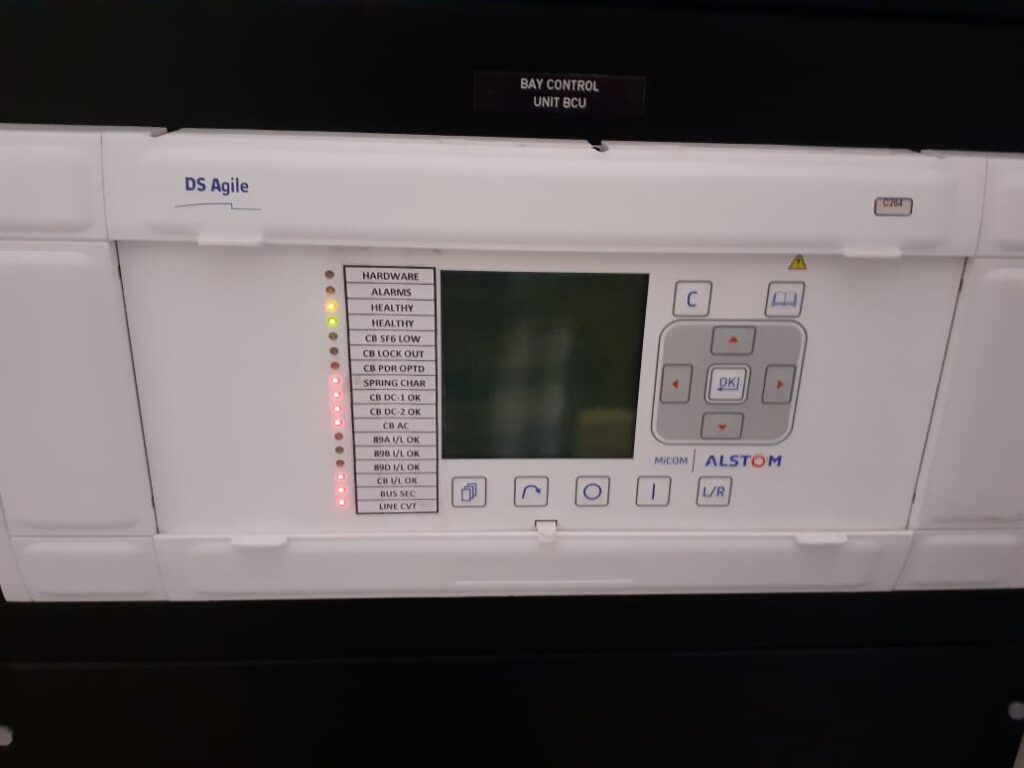
– Which software has to be used for configuration?
– Micom s1 agile. Computer Maintenance Tool from DS Agile
– For BCU, C264 we have different configuration software.
– I am communicating the 7SJ89’relay. Relay has been successfully communicated. When I save the setting to further work offline, then this error occurs. Anyone help me
– To change parameters offline you have to create another project file through MLFB of the relay.
– Is there any issue to create an impact on the IEC61850 protocol, if I create a file from MLFB and send it to the relay. Basically, our all relays are communicating from Siemens SCADA servers
– Yes, if you’re using the 61850 protocol then must have to check its RTU files as well
– is there an alternate solution. Basically, I don’t have RTU’s files.
– You can extract the file from RTU
-How to configur4e this device by Easergy energy studio? S1 studio software is used Also with S1 Agile. But necessary data modules are essential.
– When I’m trying to install it, it says already have a new version. That is nothing but Easergy studio
– Data model is empty how to add a data model in this software
– From data module manager, also with archive files if you have available then otherwise download online through data module manager
– it’s working with the data module
– Is it straight cable or cross cable?
– Can I communicate with USB to the RS232 converter?
– It requires a simple serial cable with a USB converter simple.
– Cable communication for MiCOM is RS485. Both facilities are available in one cable. Serial to USB. exactly female to USB
– The same type of fault occurred on ours Wartsila 18V32DF, 6.3KV engine driven ABB alternator almost 6 times. Checked all the circuits and connections. Found nothing. After detailed studying and checking by the Wartsila team, it has been found that the main Breaker for this alternator, auxiliary relays feeding to plc operating on 24V DC were malfunctioning.
– After being replaced with new ones, now ok. Please check your breaker close and open auxiliary relays and points.
– What do I need to configure the DSM303 module?
-Digsi5 V8 can be installed on window 7?
– Yes it is.
-So what error occurs while the install?
– Have you removed older versions before the installation of sip5?
– My laptop never install sip5 or sip4
– Is it showing any error code?
-Never
Text on WhatsApp to join our community: https://elec-engg.com/whatsapp-group-for-protection-engineers/
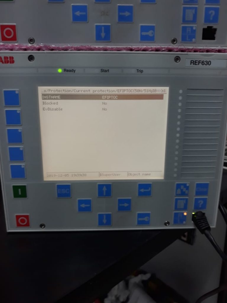
– In REF 611 we do not have an application configuration. It is meant only for backup protection settings like 50, 51, 27, 59, etc. I want to use OC trip with coordination
– I’m not certain about that. There may be inbuilt / pre-configured Binary Input for oc blocking. Please check the manual. If the inbuilt configuration is not available, we may achieve it using hardwired logic
– Can anyone guide me for the fault locator algorithm in directional overcurrent relay for 3ph fault? (without including distance protection concepts like per km resistance, per km impedance, etc)
– Hi guys anyone has ASE2000 to share? I have some tests to do. Many thanks in advance
– Can you check the serial control socket for the screen (remove the front four screws and withdraw the front cover and check the socket connection)
– Once turn off/on. Possible to setting will change or not. The setting will not be changed.
https://elec-engg.com/whatsapp-group-for-protection-engineers/
– What is the use of wire connecting bus bar and CT in 11kv ht switchgear? Can we charge the feeder without that wire?
– To create equal potential between the bus bar and ct. I mean CT equalizing wire. U can charge without it but will get humming sound and after a few years, ct may get damaged due to potential difference.
– The feeder megger value with that wire is zero, Without that wire is 500 ohm.
– Is the CT faulty? Is there any leakage through ct insulation?
-That wire is connected to resin cast and nowhere linked to primary or sec terminal
– Yes. panel megger values came zero due to moisture in the panel, so all the components were removed and cleaned. But facing the above issue with equalizing wire. If u have spare ct better change it or remove it to wire and charge in case of emergency supply restoration.
– All three phases same position. If u want to check Better apply the 440v supply across it and check the phase to gnd voltage. All 3 phases damaged at the same instance are impractical. Maybe your testing method is wrong. Test IR from the wire to the ct base plate.
– Panel filled with chemical fumes
– So that moisture formed. Thinking maybe failed due to moisture in the panel. Then u need to clean the ct outer surface thoroughly until u get to shine. Remove the cts keep it in the hot sun for 2 hrs and retest. If possible repaint it
– We do have a lot of cts in charged conditions without the wire connected from years together
– If u have a heater or halogen lamp place it near ct, Switch it on for 2 or 3 hrs.
Join our Telegram discussion group by this link: https://t.me/joinchat/Cmyg2FiXX-qlTYqyXQ_pjg
– Double operation means what? Why it’s required? It has a common interlock on the 11kV board And also 132kV GIS
– That still doesn’t convey anything to me. Double operation of what, in an interlock?
– Double operation prevention means, at a time have to perform one operation. Suppose in one Bay, you are trying to close the breaker in one breaker and parallel someone trying to close the earth switch at the same time for another bay. May chances for an accident without proper communication between them. In order to avoid this, have to set up a Double operation. For that, you have to implement electrical or logic interlockings
– Can you please share an outdoor lighting schematic diagram that can work on three modes? Manual auto with photocell and auto via BMS
– Can anybody help with the TCS programming of the Sepco III project.
– What fuel?
– It’s Coal only because it’s 660MW
– Is there any such limitations with different fuels? Why if it is with Gas/naphtha?
– No not like that. he mentioned Ultra supercritical PP. that’s is the reason I have said it’s a technology of thermal power plant without drum in a boiler.
– Yes. No drum inside a boiler
– Anyone knows how to check its coil voltages Terminal?
– Find its Internal contact drawing from the manual then check voltage from the avo meter
– 36V DC is receiving at its terminal #4,5 But relay is not getting ON
– Ohh dear its operating voltage is 250VDC/AC here in our utility
– Check its manual then connect after confirming its voltage level selection
– Its aux voltage terminals are 33,34 36vDC, But it’s still off.
– Relay power supply card might fail Because there is no healthy LED is glowing. Rack out then rack in your relay. Maybe there is some corrosion inside the 33-34 terminals.
– When we ON the breaker, it’s going off slowly after completion of the spring charge. Areva 11kv vacuum breaker
– Once check trip coil plunger and breaker buffers if brittle.
– normally we measure RMS values for the protection, right? Does anyone know where other types of quantities like DFT and Peak values are used?
-WTI range is 0 to 160 and this logic/setting is working fine. For OTI range is -20 to 140
– Any idea how will be the logic/setting?
– Which is the latest version for S1 studio agile?
– At what voltage will do PD and all? Are there any guidelines?
– It’s done at nominal rated voltage
– What’s PD?
– Partial discharge

– Currently, we are in the phase of testing and commissioning the 660MW Ultra supercritical Power plant. This will be very much helpful
– Alright. But they will cover only the basics, I think.
– Yes Sure. but sometimes this becomes very helpful, especially when using CPC100
– Normally we measure RMS values for the protection right? Does anyone know where other types of quantities like DFT and Peak values are used?
– Peak values can be used for overvoltage detection such as capacitor banks which can give fundamental and other non 50 or 60 Hz signals from the system. If DFT is a discrete Fourier transform then its fundamental detection is used for the protection
– What may be the reasons if the transformer tripped on differential?
– You have to test all captured equipment in the differential zone. Including the transformer itself.
– There is a fault or Mal operation?
– Is it a new installation? For how long has it been in service?
– Suspecting malfunction. How can I confirm?
– Do stability and sensitivity test For the last 1 month after overhaul.
– usually, if we test the relay first and find fault inside itself, most of your problem is resolved, otherwise, u have to test CTs and trafo too.
– It was reset and charged again. Values are the same as normal Can anybody say How it tripped?
– Id min is 0.1 of I base. W1, w2 are fault magnitudes, relay RET670. Id min is normally 0.2 or 0.3 PU. First of all, you have to check the fault record from the differential relay, also observe and check physical objects near Trafo i.e hot spots/animals/bird/wires, etc then closely monitor the FR from the relay
– If everything is found satisfactory then you have to go for transformer testing. The differential should not act for external faults
– Of course yes, it’s about checking all the equipment in the differential zone, Ct saturation, wrong settings.
– Finally, do an insulation resistance test on all equipment captured within the differential zone if nothing wrong is found during the inspection. Another thing that can cause frequent 87T operation is if your magnetization current (during trf ratio test) is high. It tells you there is an internal problem. It won’t trip during energization but as load increases, it will trip.
– The signal isn’t pure sinusoidal? Is there any loss termination of current circuits?
– Anyone knows why we are using this diode and what it uses?
– There are two sources, two avoid back feeding these diodes are using. Both sources change over by relay during the transient time will protect from back-feeding
– Anyone knows if we can supervise 2 separate trip circuits using a single TCS relay MVAX31?
– Don’t think so, as far as I know, you’ll need an MVAX31 per trip circuit. It’s not too expensive a relay.
– Anyone who has an omicron template file for out-of-step protection in the Simense generator relay, needs to clear this led.
– Please anybody can help me? Check trip relay
– The circuit?
– Master trip relay.
– The physical circuit or in the PCM?
– I have disconnected trip
– What was assigned to that led?
– Supervision
– if that is Trip circuit supervision, and you have disconnected (the trip circuit is open), then the LED will glow as indicated.
– That’s because there’s a missing (-ve) from the trip coil being supervised. Hope your mcbs are on.
-Don’t worry your LED did as it was expected (as soon as it detected a break in your trip circuit) 😊
Be a part of our problem-solving discussion groups: https://elec-engg.com/whatsapp-group-for-protection-engineers/

Elec-engg.com
– Can we force Digital input and digital output in the MICOM relay? And how?
– https://youtu.be/7l1Qqip1W8E
– Above is for Outputs. For Binary input high just short at the terminal block, for Low drop the voltage settings in Opto inputs menu. *Increase the volts
– How could I disable this counter? It won’t let me test the relay
– Make thermal setting off and try
– who could help in understanding the process of turning ON/OFF the breaker through the relay?
– using binary outputs of the relay as opening/closing button,
– what type of cable do I need to configure ABB relays?
– Simple UTP cable with Rj45 connectors
– That’s an Ethernet RJ45 right?
– Yes
– Also you have pcm600 setup with updated device manager of your specified IED Like ABB Ref615, Ret670, etc
– Okay, but doesn’t the PCM setup come with all device drivers?
– No, you have to download and install the respective device driver through the device manager of PCM
– In Help click on Update manager then select your device
– We are commissioning PCS-985 Transformer Protection Relay NR Electric For 660MW Coal-fired power plant.
– 1. Overcurrent (Highest for HV bushing faults).
– What is your transformer winding configuration?
– Is this a generator transformer ie power is being exported out through the 500kV trafo. bushings?
-This is a start-up & standby Transformer for energization of the auxiliaries before the power has been generated.
We have two transformers. One is a Generator transformer 22/500KV. The second is a startup and stand by transformer
– Ok, so you’re generating at 22kV and exporting out at 500kV. You are feeding 11kV auxiliaries thro’ 11/500kV trafo.
– Ok, because of the power flow, I think the highest for bushing faults that I mentioned may offer little benefit in your case.
– what You will recommend for this?
– This normally works for grid transformers deep within the transmission side where power flow is from HV to LV say 500 kV to 220 or 132kV.
– is our protection scheme OK?
– I think you are pretty much covered. The highest OC is normally useful to detect bushing faults on the HV side and remains stable for LV side faults provided the power flow is from HV to LV.
– Can you send me a quick snapshot of your SLD? I just want to see how the transformers are connected and the earthlings.
– What about over fluxing Protection?
-Spot on, definitely needed for general Trafos.
– Startup and stand by transformer Means a different relay is used for V/F
– In DIGSI 4.88, is it possible to store the DR automatically in the local disc?
– No
– Use PQ collector
– Thanks, is that a separate application?
– Yes provided by siemens with DIGSI 4.91

– How to reset thermal lockout time in GE M60? Should I use both element 51 (overcurrent) and element 49 (Overload) for the same motor?
-Its name is sicam pq analyzer. U need to purchase it from siemens.
– Anyone guides me about i/iN >
– Ratio of setting current to rated nominal current
– > means low set, >> means high set
– Usually, this is the approach, Ct ratio is 100/5. IN = 5
– My load is 15amp HT, I want to trip it at more than 15amp.
– Relay coordination is required For timing
– Usually, this is the standard they follow in all utility For 11kv they keep 500ms
– Can u tell me the calculation?
– This is a high set indicator in relays.
– This is true? iN =CT ratio current 20Amp
– Not all places
– High set to 6 depends on the downstream load nature. Like a motor or transformer. If plain fdrs then we can even go down. Better to check also with utility followed standard In is CT secondary 5A
– Not in kseb
– Even in kseb the time setting is 500 ms for 11kv
– I do consultancy to kseb. We don’t use it everywhere
– But state utility will allow 500ms delay for 11kv level
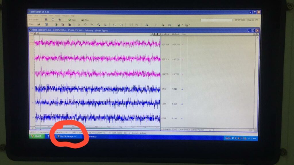
– I need Eplan or other software for the electrical design dept. Is this actual fault that happened in the transformer Or this inrush current? According to the disturbance recorder.
– YES. Better to test relay and CT’s, even though inrush current exists it should be normal before the time delay of tripping, also check voltage profile Fault.
– This is a fault at phase ground
– If there is a wave gap present in two phases and other phase symmetry then it can be an inrush
– Usually, it is instant, no delay tripping for Diff protection
– Just enable in-rush / 2nd-harm blocking for Diff Prot.
– Can anyone help me with how to auto reclose test in the 7vk61 relay?
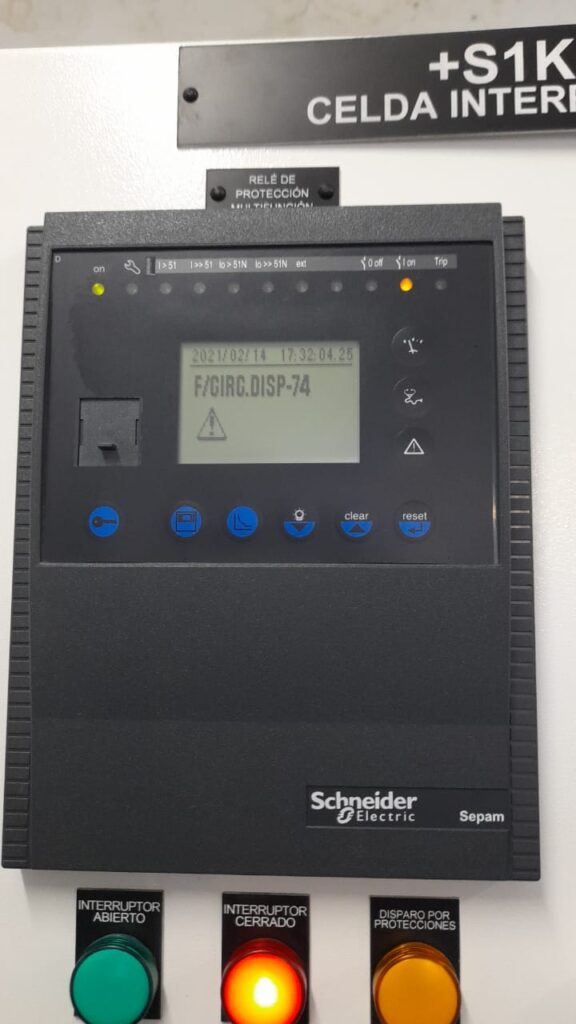
– Could anyone tell me what happened with the relay.
– Check if the relay is connected to an SNTP Server. Perhaps, this is why it may have failed.
– It could be a battery replacement. Further, check this error code from the manual.
-you can see the trip time is not correct
– What is this software?
– Power DB 11.2
-For this equipment Is 5700A primary pickup correct?
– No it doesn’t
– CTR in the primary side is 30:5. im.The differential test is Ok but the OC test does not match operating times
– Isn’t primary supposed to be 1.14kA instead of 5700?
– This value is 5,7A, not 5700
Be a part of our discussion groups: https://elec-engg.com/whatsapp-group-for-protection-engineers/
– Hello, I have a problem with this relay, I changed the recloser batteries and after that, the relay no longer wants to work, it is worth mentioning that before changing the batteries, energized with AC voltage, the relay worked well. Now it just presents this fault and doesn’t show anything on the screen, can anyone suggest something to me? Is the relay damaged?
– what’s causing the issue? before you changed the batteries, everything was fine. So what was the driver behind changing the recloser batteries? Did you try rebooting the relay?
– What happens if you put the old batteries in again? Would it go back to the initial point, where it was working OK?
– Just using the usual troubleshooting algorithm in doing a bone analysis.
– Indeed the recloser did not have a DC backup since the old batteries do not work (the relay was operating only with AC voltage), we have already tried to put the previous batteries and it does not work. Still not trying to reboot the relay.
– Can Anyone please send the data model for P14NB11A2B0510A
-Dear you can Download it online via the data module manager.
– is the trip circuit for the 33kV VCB board. What is the function of B6 & B8 (mark in a circle) here?
– For trip circuit supervision function. On CB off condition, both inputs will be high. On CB on condition 1 input (b2&b4) will be high
– Ok. What happens if the remote trip is continuously high? Is it the result of continued energization of VCB trip coil or Binary input (B6/B8) that prevents sending a continuous trip command to the trip coil?
– Both IPs will be low during trip command.
– This is nothing but pre and post-close BI
– Hi everyone Can anyone give me details about the weak infeed for distance protection? how to operate And which scheme I find it. PUT scheme or Putt scheme
– Weak end infeed is used as a part of the POTT scheme in areas like wind farms
– Please, I have an issue with *Micom P442*. Some LEDs do come up and can’t be reset via HMI, but we do use software to reset.
– How do we solve this issue, please?
– You have to add LED reset function from the PSL logic page through this you will be able to reset LEDs from the assigned key, thanks.
– Okay, how do I do that, please?
-Communicate with the relay through s1 agile then download setting+psl then open PSL and make a login to the reset button.
– Okay but I don’t know how to make a login to the reset button, please. I can communicate with the relay, download setting + PSL, and open PSL
– This is simple, you just have to set fault to reset to your chosen key simple. Otherwise, you can take help from YouTube
Be a part of our discussion groups: https://elec-engg.com/whatsapp-group-for-protection-engineers/
Our completed Courses:
- IEC 61850 Configurator Training (4 Hrs)
- DIGSI 4 Offline Video Training (3 Hrs)
- DIGSI 5 Offline Video Training (7 Hrs)
- ETAP VIDEO Training (5.5)
- PSCAD Video Training (4 Hrs)
- PCM 600 Video Training (3 Hrs)
- MiCOM Relays Training Package (4 Hrs)
- Testing and Commissioning of Protective Relays

Elec-engg.com