

Discussion samples in the group:
– Transformer Diff relay Micom p632 making alarm any idea to reset relay.
– It’s a false alarm Clear the fault log operational log.
– But still, alarm coming. The relay may be faulty. If the fault cleared try to do a force reset under options in the record.
– The third harmonic in all the 3 phases when added doesn’t become zero rather it becomes 3 times the phase value which becomes a very high value. To nullify any of the 3 rd harmonics presented in primary transformers have tertiarily connected in the delta which forms a closed-loop for the 3rd harmonic current in the secondary side thus canceling the 3rd harmonic present in the primary side by transformer action. The alarm may be a communication alarm, Then go to the communication setting and disable some functions.
– Pls confirm whether this relay is in service at SAS or conventional ss.
– Here what type of winding connections are used? Does anyone know the name of this connector
– Connector DB9.
– Can anybody share the calculation for the rising of potential in healthy phases when there is an LG fault in the resistance grounded system? Why not show the current popup menu but the measurement ok 25A flowing inline current please anybody help me happen like this.
– Check the signal mapping of ‘I’ in the GDE tool in PCM. What is the sampling frequency/rate of a relay?
– 50Hz During event time also.
– To connect Sicam Siemens software from the laptop through ethernet to the fault recorder which IP address combination will be used?
– Config view.
– Does it support Modbus?
– Yes.
– Sir anyone can please anyone provide me with the structure drawing and details for mounting (11kv/0.415Kv) 315kVA and 200 kVA DTR?
– I am testing neutral CT connecting to the PR122 device of sace breaker by injecting primary current and measuring secondary current. But at 2000A it is giving 5 mA. How is this possible? This behavior is ok?
– CT ratio?
– Double pole drawing
– Check the inside of the relay for any loose card -probably input card On only written 2000 A max. No ratio is given. Short the CT secondary terminals and then inject the current.
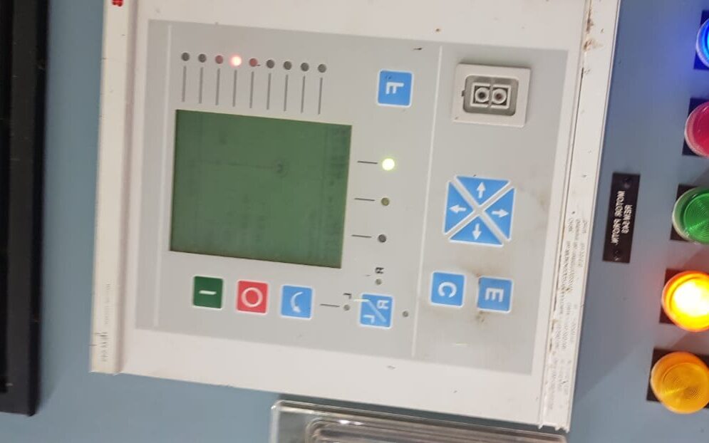
– How to go to settings in this relay setting group? REM 543
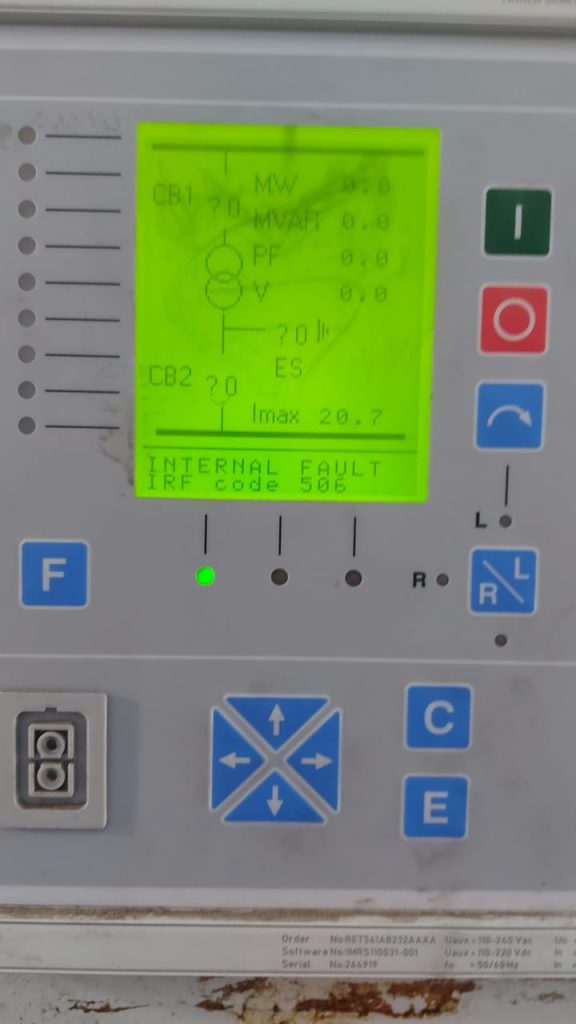
– What is the meaning of IRF CODE 506 for relay ABB RET541?
You can also join our WhatsApp groups. Participate in problem-solving (Click)
– What is this alarm (MR user alarm 5) in P-343 Micom Relay?
– Is this from Edvard Csanyi/EEP?
– EEP Yes
– How many clients can an IED report to? Is it limited to vendor/OEM specifications or is it defined by communication protocols?
– limited by provider
– Might depend on the number of report control blocks
– This is correct. But all reputed companies provide 5-7 connections.
– You mean 5-7 concurrent client-server sessions Or 5-7 report control blocks?
– Does it include IEC-61850-based Transformer diagnostics?
– The RCB or the URCB can connect 5 clients some of the relatives have the index function they want to decide if their index is 2 open 2 RCB for both 2 clients can receive data.
– Reminder could anyone please help me out?
– How to reset the alarm?
– Check the PSL file and look at the logic of this alarm.
– The alarm is the MR User Alarm (Manual reset user alarm). So it may be assigned in the PSL. And try to trace to what purpose it is assigned.
– Are there any Substation Automation engineers in this group working in Vendors/OEMs?
– I was just looking to network with OEM engineers; at least one from each.
– Alarm can not reset
– Maybe the relay is faulty
– Micom some of the is had these issues.
– Check the case of the relay and contacts of the relays are intact. Try resetting the maintenance record.
– How can we reset the maintenance record. in the Micom p442 relay
– I need a cable sizing calculation Excel sheet And Earthing sizing calculation in Excel sheet as per IS 3043
– Go to Google download cable size app
– There is an application for that and with the app, you can check any cable size
– Does anybody have the documents for relay coordination in the power plant please share them.
– what is the temperature effect on the Ultimate breaking capacity and service breaking capacity of MCCB?
– If the ambient temperature is 70°c.
– What is meant by multilayer earth resistivity?
– Soil may not be homogeneous sometimes. its top layer may be sand for example up to 2 m from the surface but its bottom layer may be rock after 2 m. In this situation, multi-layer earth resistivity modeling is required for earthing system design.
– Does anyone know how to make a transformer position simulator?
– if the Input type is bcd, you need to look for the bcd input I do not remember exactly the location just check the drawing then you need to feed this input with dc.
– What is the philosophy to set under-voltage settings for 415V and 6.6 KV buses under voltage? What is the correct configuration of a serial cable to communicate with this relay?
– You can check the same in the relay itself. Serial cross cable.
– I want to prepare one to be ready in case of failure of the installed one but I don’t work on protection relays before
– You have to download the program from the one already installed and upload it in the spare one. For that, you need to download the software sft2841 from the Schneider Electric internet site.
– The relay has a fault and stops working. How to reset it?
– It is not possible to reset manually. you need a DRS cable and software for that.
– Hi Group members Is anyone who has an idea about delta-connected CT and its purpose?
– This is the visuals during the 11kv used cable dc hi-pot test at 10kv dc. Leakage current is hunting up to 0.1ma during voltage rise. kindly suggest if is it ok or not.
You can join our WhatsApp groups. Participate in problem-solving, CLICK
– In the last two days two of our transformers were tripped on backup earth fault protection and both times NGR of the transformer burnt partially. Both timeline currents are equal only the current sense by neutral CT is 300 amp. The Ngr rating is 300amp for 10sec of 11kv. We also checked the bus duct connected between the transformer and switchgear but nothing abnormality was observed. Then we charged the transformer. Please guide me from where the fault may take place.
– Where line current is equal but neutral current is increased.
– 31.5mva z-12% voltage ratio-21kv/11kv vector-dyn1 and CTR is 1000/1 in hv side and lv side 2000/1.
– Does the neutral current of the LV side of the transformer obtain from the summation of three phases or does it have another Neutral CT?
– It had neutral ct at transformer neutral of 300/1 ratio. Is there any other transformer nearby or this transformer earthing is individual or connected with common earthing?
– A separate earth pit is there.
– The second Unit transformer and station transformer is nearby that transformer.
-Any welding machine is in operating condition to that transformer
– Just check about this point. Because many times it happens in many plants also.
– We are using Micom p345 relay for generator protection. For GR1 AND GR2 both. 100%SEF protection is a low-frequency injection scheme. In normal conditions, GR1 relay reading 64SI in microampere whereas GR2 relay reading in milliampere hence generating 100%SEF in normal conditions. We have checked all the electrical circuits but have not rectified them. Need suggestion.
– We have a 380v pre-heater installed for the diesel generator controlled through the contactor. Contactor one phase, not same always burns after few months. Sometimes in 3 months and sometimes more than this. Heater resistance merging voltage rating everything ok. The running current of the heater is 80 amp and the contactor is 95A Schneider
– Please suggest where there will be a problem.
– You need a very good internet connection
– What is the difference between high impedance & low impedance bus bar Protection?
– First, the biasing is provided externally usually using a stabilizing resistor. The second one is internally through logic. Usually, low-impedance relays are numerical and high-impedance relays are static.

Elec-engg.com
– how to communicate older firmware Siprotec devices in DIGSI 4.92?
– I am trying to communicate Siprotec protection devices in DIGSI 4.92
– Download the exact driver version from the Siemens website
– firmware version 4.71 driver is not available for DIGSI 4.92. please provide if any resource is available
– Can’t you request firmware for this IED that is compatible with D4.92? Even if it’s an older one?
– Which IED?
– 7SA522 distance protection
-Then you may use digs 4.93
– Does 4.93 support older IED firmware which 4.92 can’t?
– This has nothing to do with firmware support. the parameter set in your current DIGSI 4.92 is higher than V04.73.01. you need to uninstall that parameter set from your pc or laptop and install the parameter set of V04.71
– Could you please elaborate on the steps?
– I don’t remember exactly. to uninstall a particular device parameter set. maybe right-click for the device catalog
Find out the device. under that device find out the version.. select it and right-click for uninstall. After that install the required version as normal procedure. Because for installation for higher version this version is needed

Elec-engg.com
– anyone please suggest to me a list of protection required for 11kv/440v 630kVA trafo.
– it’s based on what kind of load you’re going to connect on the LV side
– load at the lv side.
– Overcurrent earth fault ( differential if required)
– is there any other protection like thermal oil temp ext required?
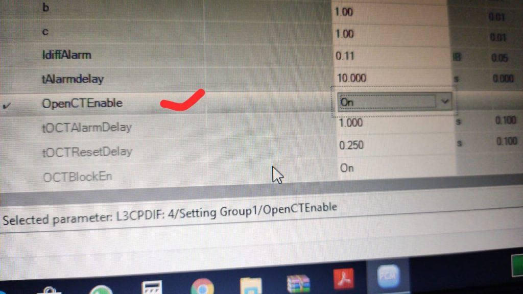
– Why not download the CID file please anybody help me? While installing it is asking for a lower version first
– Thermal for motor protection.
– Transformer mechanical protection is Bucholz relay OSR PRV winding temp oil temperature. these are 5 major mechanical protection for trafo
– In our 33kv feeder unwanted tripping is coming due to fault in other feeders by differential protection in 7sd Siemens relay we came to know that feeders in one station CT are px and the other is 5p20 used for differential protection and showing fault current passed is having more than setting. Is it sure that the tripping is due to different CTs if it is how to avoid through settings in 7sd relay?
– The feeder in one station is showing a 1.26k fault in-phase and the other is 1.01k. the difference is more than setting causes the tripping.
– I want to change the setting but relay want a password please tell me what password given
-222222. 2- 6 times.
– Any difference while the same is installed on the 132 kv line? Please
– What is LDC here in this photo?
– 3
– Is there any difference between the +45 or the -45 RCA angle?
– no
– Then some relay the mentioned RCA +45 and some other -45?
if you don’t know how you can get your professional problems answered, You can share in our discussion group, CLICK
– Hi Experts Anyone familiar with Toshiba GRB 100 Bus Differential relay for Low Impedance BB Protection? if anyone used please let me know the Bay Unit required for each feeder or we can use CU for all the feeders kindly please advise your advice is highly appreciable in this. Thanks
– It seems to be an HMI converter cable
– Which type of protection relays are installed on all breakers? secondly, what are the time setting and plug settings of the source breaker that is feeding the 33Kv line from the remote end?
– 05 sec of the source end
– I need to do the setting for over current double overcurrent and earth fault. I need a proper method to calculate the settings
– you need the fault level on the H.V side both 3ph and 1 ph fault level transformer impedance and x/r ratio setting of H.V of the relay then do the fault calculation then only u can calculate the setting for relay coordination for OC &EF.
– 10mva transformer with %z=8.35
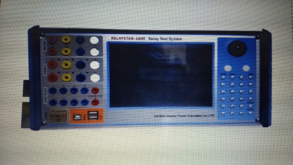
– Anybody helps me how to operate this test kit as omicron features
– Use a laptop to install PowerDb software & connect by Lan cable
– Can you give me the software
– Download from the Megger website. Check-in Google for power DB…
– How to get PTL.
– It’s already in the software.
– Anybody knows what is 81T Protection Signal is?
– T is for trip Transformer
– 81 frequency relay
– 81H over frequency 81L under frequency 81R rate of change of frequency
– Why is simulation mode disabled coming? how to actively enable? Please help me
– When you restart you have to select either simulation or not?
– Hey Anybody has done IEC61850 comm of SICAM Q200?
– Anybody can help please how to solve this issue for busbar protection type 7ss50
– What is the problem with this device?
– Alarm appeared and disappeared many times.
– C – correct polarity. The dot represents the current entering & leaving. Polarity wise C is okay and Connection wise A & C is okay
– Polarity A is ok. The rest is wrong. The reading in the polarity B and C is zero
– Hi, When I closed the 300mva tr tripped from HTS in the differential relay. Is this an actual fault or an inrush current according to the disturbance recorder?
– On your relay check the status of for harmonics restrain block option I
– It seems there is confusion between the B phase and N phase in the ct. Because of that diff tripped
– See the second harmonic content in the inrush current with time and compare it with your setting you will get the idea
– During the REF out zone fault primary side current was injected 50A and measured in neutral 50A in and the upstream relay also showed 50A but the REF relay showed 36A only. what may be the reason?
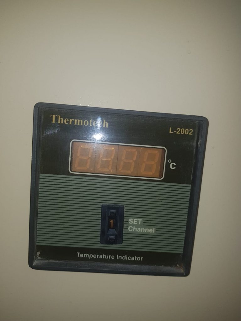
– When MCB is ON at that time why the current does not flow through the indicator as it is connected to a live wire
– MCB -low resistance path compare to Indicator
– I think this may be the reason. The indicator needs both phase and neutral. But this connection seems like it used the same phase wire before and after the MCB so it may need to be connected in parallel to the load if you wanted to check the indicator. I think this is can be the appropriate answer
– The indicator will glow only when MCB is off/ tripped
– When MCB is on, there is no voltage diff across the poles. That means there will not be the current through MCB.
– I doubt that MCB is On why the current doesn’t flow through the indicator and why it doesn’t glow.
– The contact resistance is very low when MCB is closed. A small amount of current will flow through the indicator for sure but this will not be sufficient enough to glow the indicator when MCB is closed
– MCB is useless here. When MCB is off if the load current is huge it will blow up the indication and lead to a disconnected load. However, if the load current is less so that it falls in the rating of indication load will always be ON no matter if MCB is on or off.
When MCB is on load current will follow the least resistance path and will be shared between MCB and indication according to their resistance. Less current will flow through the indication which will be small enough that it will not be able to cause illumination of the indication. *MCB is On
– Load current depends on series impedance + load impedance and driving voltage. If the load impedance is very low the series impedance will decide the magnitude of the current if the voltage is constant. The indicator will never blow. The purpose of the indicator is to monitor the tripping of MCB while the load remains in the circuit. The indicator behaves as connected on the same phase if case MCB is closed and acts as connected across when MCB is on.

– In the running condition of the motor, LTMR is not showing current as well as operating time also not increasing. What to do?
– Polarity change single-string leads to burn total S.M.B
– First, confirm the current by clamp meter if it showing normal. Why I can’t connect iedscout from our Siprotec 5? Ied scout could not discover an IED but I can ping correctly.
– Trafo.REF testing 100A injecting Residual current Io showing 73A and Io’ showing 32A, can anyone be aware of the Schinder relay?
– Mostly due to supply card problems or checking the fuse blown
– High impedance REF? Or low impedance REF? You also have to check the wiring in the analogic residual input Io and Io’
– High impedance. Phase CT and NCT Both are 5000/1. We changed the new relay and also
– Io only wiring considered 7&9 as per drawing, No wiring for Io’.
– Anyone can please help to connect the NARI relay using its software? The LCD screen sticks on the MR logo and the watchdog contact closes and gives the alarm. I tried to rest by switched off and on again but still not working
– Check the CT polarity connection to the relay
– Perform a stability test to identify that if possible.
– I changed before showing 12 A less after changing 15 A more. Then check phase ct connection one by one
Perform stability it will clear
– Hi 220vdc MCB tripped in the control panel with the source breaker also tripped
– MCB is not selective they trip at the same time at a short circuit. It is better to use fuses to select CBS in the DC-Distribution
– 1. Check whether you used DC application MCB or not. Check what type of curve MCB is used in your panel in line with your load type.
– In my knowledge Selective type is only available in the RCCB AC type A type B type.
Text on WhatsApp to join our community, CLICK
– Can anyone explain when and why a numerical distance relay like GE D60 and Micom P443 read fault location in -ve value for example -22.5 km
– Reverse zone fault
– Fault is in the forwarding zone, Reverse zone is blocked
– Vactor group Dyn11 Side-A Delta Side-B Star when I star side Phs-A fault given that time phs-A Bphs fault when B PHS fault given that time B-PHS C-PHS fault coming when C-PHS fault given C-PHS A-PHS fault coming.
– Verify CT polarity.
– One by one check. CT polarity distance settings whether conductor parameters are right and line length.
– Relevant to the protection/engineering team in Generation plants. I am getting this error when I send the application configuration to the relay REF 615.
– what amperage handles this type of fuse? HSW 15/ 24kv
– 3A
– Anybody knows how the tap changer position indicator works? For a remote indication
– How it is interfaced with the remote? is it through AVR?
– as far as I know, there is two way to represent the first one is through 4_20 ma Or BCD
– Do you have any article or document that explains that?
– what is the type of AVR?
– Reg-da
– If it uses BCD what value send to AVR sir? DC voltage or?
– Yeah it is a volt Dc
– That value Will be read like binary code? isn’t it? before converting to decimal anymore?
-Then how about measuring the transducer in OLTC? Why it is needed? Why doesn’t use contact as usual (NO/NC) to indicate the tap changer’s position?
– I do not know why but what I know is there is two way to represent it, are you going to send the position to the control center or just to the level of AVR
– The problem is with the AVR. The tap position doesn’t show on the AVR screen. So also doesn’t show on SAS PC.
– What is the position of the tap now?
– First, you have to know your tap in which position then check the input of the AVR to make sure the equivalent BCD is receiving the full dc. Then check to set in AVR that you are choosing the display type as BCD.
– The Connectivity Package has sent a status message: PCM Configuration and IED Configuration are not matching. Can not start Monitoring
– Right-click on the IED and select read IED. the configuration in the IED will be downloaded in the PCM project, then u will be able to select online monitoring
– I have downloaded all settings before and unplugged the communication cable then I change some parameters and add some logic. now I need to upload but that massage appeared
– Project in PCM and IED shall be the same. Then only online monitoring is possible.
– Yes you will have to upload that project in IED With whatever modifications you have made Write to IED option will be there.
– U made the configuration for the whole project offline right? Which is the port using the rear or front? fiber-connected “in-ring” between relay or not?
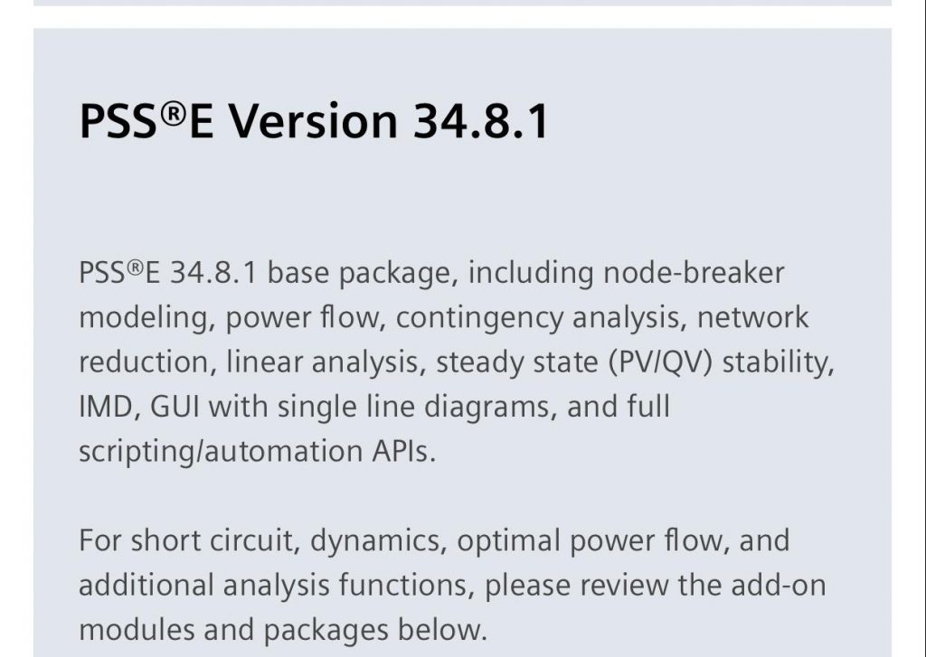
Does anyone have an SKM power tool crack?
– Only for V7 which is too old
– Plz suggest a numerical type under frequency relays. Plz suggest under/over frequency relays
– 81U/O
Hi please help me how to add a circuit breaker interlock with frequency protection in REU 615
Our completed Courses:
- IEC 61850 Configurator Training (4 Hrs)
- DIGSI 4 Offline Video Training (3 Hrs)
- DIGSI 5 Offline Video Training (7 Hrs)
- ETAP VIDEO Training (5.5)
- PSCAD Video Training (4 Hrs)
- PCM 600 Video Training (3 Hrs)
- MiCOM Relays Training Package (4 Hrs)
- Testing and Commissioning of Protective Relays

Elec-engg.com