
Power System Protection for Beginners
Start your journey into Power System Protection with this practical, engineering-focused training course.
Designed for beginners and early-career engineers, this course explains the fundamental concepts of power system protection, substations, fault analysis, numerical relays, and protection schemes before moving into practical engineering using Siemens SIPROTEC 5.
Through step-by-step explanations and real engineering examples, you will develop the knowledge required to understand how modern protection systems detect, isolate, and clear faults to maintain a safe and reliable power system.
What You Will Learn
- Power generation, transmission, and distribution fundamentals
- HV substations and their primary equipment
- GIS and AIS substations
- Current Transformers (CTs) and Voltage Transformers (VTs)
- Protection and control panels
- Electrical schematics and protection single-line diagrams (PSLD)
- Power system faults and fault detection principles
- Protection philosophies and ANSI device numbers
- Numerical relay fundamentals
- Protection relay selection
- Practical engineering with Siemens SIPROTEC 5
- Relay online monitoring, Web UI, measurements, event logs, and fault records
- Configuration of Overcurrent (50/51), Earth Fault (50N/51N), Directional Overcurrent (67), and Directional Earth Fault (67N) protection functions
Who Should Enroll?
- Protection Engineers
- Electrical Engineers
- Commissioning Engineers
- Substation Automation Engineers
- Maintenance Engineers
- Electrical Engineering Students
- Anyone beginning a career in power system protection
Course Features
- Duration: 13+ hours of pre-recorded video training
- Beginner-friendly, step-by-step approach
- Practical demonstrations using Siemens SIPROTEC 5
- Real engineering examples and case studies
- Downloadable reference materials and supporting files
- Lifetime course updates
- Certificate of Completion
Whether you are a student, graduate engineer, or experienced professional entering the protection field, this course provides the essential knowledge and practical skills needed to build a successful career in Power System Protection and Substation Automation.
Chaper 1: HV
A: Power Generation and Transmission
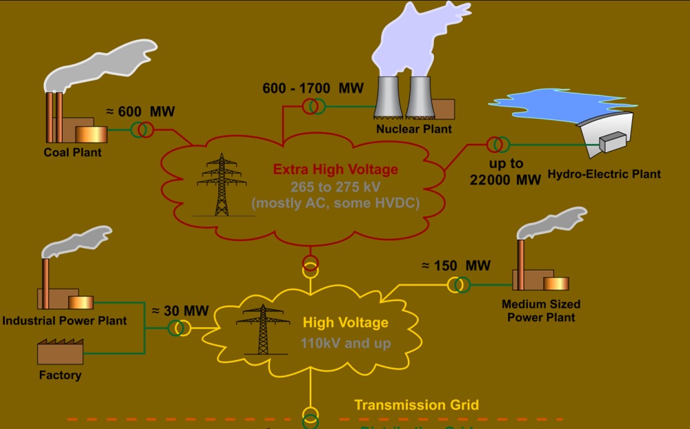
- Basic overview of Generation and transmission
- Power System components
- World electricity generation
- Single Line Diagram (SLD)
- Power Generation Technologies
- Hydro-Electric Power
- Hydeo Power Plant in India
- Fossil fuel power
- Coal Power Station in India
- Nuclear power generation
- How does a Thermal power plant work?
- Wind energy
- Solar power
- Power Grid Infrastructure
- Electrical grid
- India National Grid Map (N, NE, S, W, E)
- European-wide synchronous grid
- National Grid
B: Substation and Its Components
- HV substation in India
- Type Of Substations
- Elements of Substation
- Power Line
- Ground wire
- Wave trap
- Potential transformer
- Disconnect switch
- Earth switch
- Circuit breaker
- Current transformer
- Lightning arrester
- Main transformer
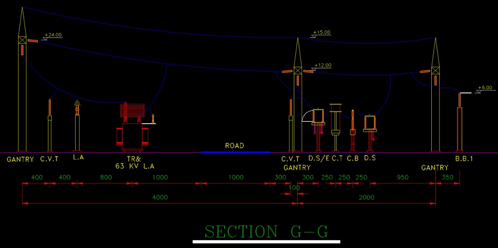
- Substation Layout
- 400/63/20 kV substation layout
- General Single Line Diagram (SLD)
- Protection Single Line Diagram (PSLD)
C: Type of Busbar Configurations
- Single Bus-Bar Arrangement
- Single Bus-Bar Arrangement with Bus Sectionalized
- Main and Transfer Bus Arrangement
- Double Bus Double Breaker Arrangement
- Double Bus Single Breaker Arrangement
- One and a Half Breaker Arrangement
D: GIS substation
- GIS history
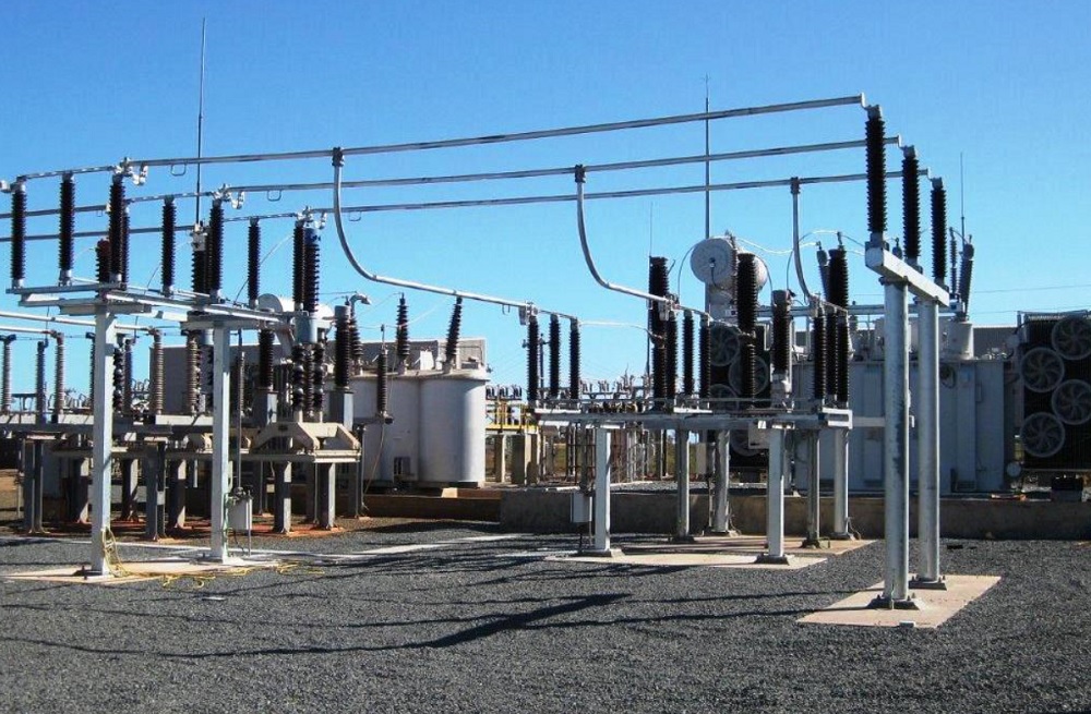
- GIS Vs. AIS
- GIS installation
- Maintenance
- GIS elements
E: Instrument transformers
- Why are instrument transformers needed
- Voltage/Potential Transformers (VT/PT)
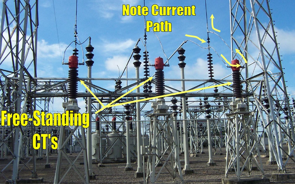
- Current Transformers (CTs)
- Basic working principle
- Bushing CT
- Free-standing CT
- Pass-through CT
- Window-type CT
- Bar-type CT
- Wound type CT
- High voltage CT
- Tank type CT
- Top-core CT
- CT Ratio
- CT Polarity
- Excitation
- CT circuits
- VT circuits
- Metering Core
- Protection Core
- CT classes
- CT shorting block
E: Instrument transformers Supplementary files:
We’ve gathered some helpful resources about instrument transformers to support your study.
- Current Transformer Basics
- CT REQUIREMENTS FOR GE MULTILIN
- DIMENSIONING OF CURRENT TRANSFORMER
- Current transformers: How to specify
- Protection Current Transformers (CTs)
- Current Transformer
- Selection Of Current Transformers
- Current Transformers
- Current Transformer [CT] Presentation
Chaper 2: LV

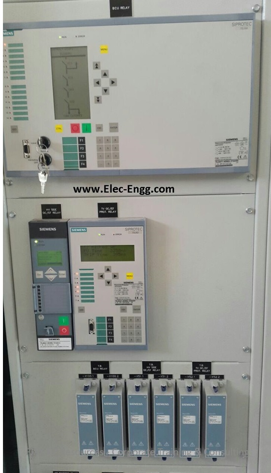
A: Control & Protection Panel
- Introduction to Control Protection & Metering System
- Type of Panels & their usage
- Panel Construction & Components
- Control Panel
- Synch check
- Panel Accessories and Components
- Terminal Blocks
- Metering Components
- Wiring Components
- Control Switches
- Protection Relays
- Automation Components
- Protection Panel
- TCS Relay
- Trip Relay
- Lockout Relay
- Annunciator
- Electromechanical Relays
- Static Relay
- Numeric Relays
- BI/BO, AI/AO, CT/PT, NO/NC, Communication Ports.
B: Schmeatic Diagram
- Introduction to Electrical Drawing
- Typical Electrical Drawing Symbols
- One-Line Diagrams (Single-Line Diagrams)
- Overview of CRP Schematics
- Connected line or wires
- Wattmeter
- Varmeter
- Opened contact
- Closed contact
- Current transformer
- Current transformer with marked polarity
- Ammeter
- Voltmeter
- Thermal relay
- Three-winding three-phase transformer
- Overlap Line or wire
- NO contact
- NC contact
- Coil
- Emergency switch
- Contactor
- Changeover
- Selector Switch
- Push button
- Power factor meter
- Frequency meter
- Therma OL relay
- Timer
- Terminal
- Auxilary contactor
- Panel and Equipment Layout
C: Protection Classification, Types & ANSI Codes
- Common Acronyms
- ANSI Standard Device Numbers
- 21 Distance Relay
- 21G Ground Distance
- 21P Phase Distance
- 24 Volts-per-Hertz Relay / Overfluxing
- 25 Synchronizing or Synchronism-Check Device
- 27 Undervoltage Relay
- 27P Phase Undervoltage
- 32R Reverse Power
- 46 Reverse-Phase or Phase Balance Current Relay or Stator Current Unbalance
- 49 Machine or Transformer Thermal Relay
- Thermal Overload 50 Instantaneous Overcurrent Relay
- 50BF Breaker Failure 50N Neutral Instantaneous
- Overcurrent 51 Time Overcurrent Relay
- 51N Neutral Time Overcurrent
- 51V Voltage-Resistant Time Overcurrent
- 59 Overvoltage Relay
- 67 Directional Overcurrent Relay
- 67N Neutral Directional Overcurrent
- 79 Ac Reclosing Relay / Auto Reclose
- 81O Over Frequency
- 81U Under Frequency
- 86 Locking-Out Relay
- 87 Differential Protective Relay
- 87B Bus Differential
- 87G Generator Differential
- 87GT Generator/Transformer Differential
- 87L Line Current Differential
- 87RGF Restricted Ground Fault
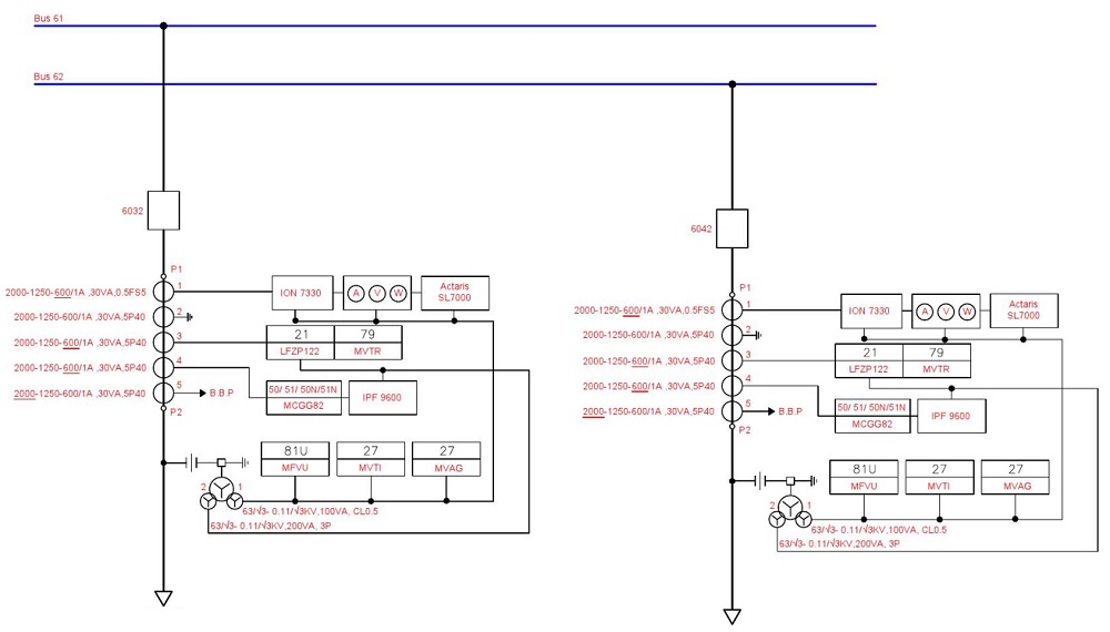
D: PSLD (Protection Single Line Diagrams)
- Transformer protection single line diagram
- Line protection single line diagram
- Busbar protection single line diagram
- Feeder protection single line diagram
Chaper3: Faults
A: Faults
- Normal Operation of Power System
- Abnormal Condition of Power System
- What is the fault
- Abnormalities
- Types of faults
- Faults in Windings
- Symmetrical fault
- Unsymmetrical faults
- Fault statistics
- Transmission Line Faults
- Earth Fault on H.V. External Connections
- Phase-to-Phase Fault on H.V. External Connections, Internal Earth Fault on H.V. Windings
- Internal Phase-to-Phase Fault on H.V. Windings Short Circuit Between Turns H.V. Windings
- Earth Fault on L.V. External Connections
- Phase-to-Phase Fault on L.V. External Connections, Internal Earth Fault on L.V. Windings
- Internal Phase-to-Phase Fault on L.V. Windings Short Circuit Between Turns L.V. Windings
- Faults in Generators
- Generator Stator Earth Fault
- Generator internal faults
- Faults due to the load
- Overload
- Unbalance Load
- Loss of field
B: Fault Simulation and Studies
- Fault calculations
- Symmetrical Components
- ETAP
- DIgSILENT PowerFactory
- PSCAD
- Single-phase fault simulation
- Three-phase fault simulation
- Earth fault simulation
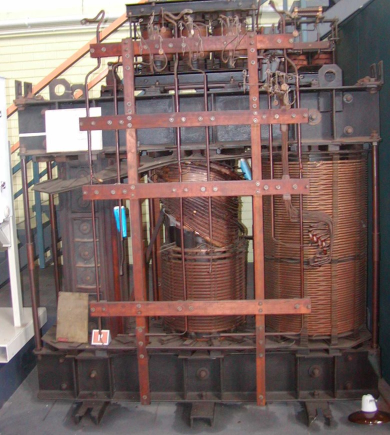
C: Criteria for fault detection
- Overcurrent I>
- Earth-current IE>
- Current unbalance (negative sequence current I2>)
- Undervoltage U<
- Overvoltage U>
- Over- and Under-frequency
- Leakage (Differential) current
- Underimpedance Z<
Chapter 4: Protection
A: Protection Introduction
- Importance of the Protection System
- What do we want to protect?
- Function of protection systems
- Requirements for system protection
- Elements of a Protection System
- Primary Protection
- Backup Protection
- Zones of Protection
- Primary and Backup Protection
- Protection Relay History
- Electromechanical Relay
- Static Relays
- Numerical Relays
B: Numerical Relays
- Numerical Relays
- Advantages of Numerical Relays
- Structure of Numerical Relays
- How do Numerical Relays work?
- Analog to Digital Conversion
- Digital Phasor Measurement
- Example Feeder protection
- Numerical Relay Manufacturers
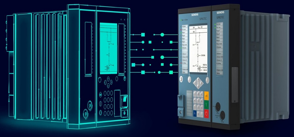
C: Relay Selection Guide
- Available Device Types
- Fields of Application
- Medium-Voltage Application
- Transformer Protection
- Generator Protection
- Line Protection
- Busbar Protection
Chapter 5: SIPROTEC 5 Online Mode
A: Online Mode
- Relay Offline Vs. Online Mode
- Device Information
- Config Information
- Process Mode
- Commissioning Mode
- Simulation Mode
- Edit device time
- Copy the online device to the project
- Assign an online device to the project
- Change the assigned device
- Create a backup from a device
- Load the Configuration to the device
- Retrieve Device Data
B: SIPROTEC 5 Web UI
- Device Information
- Relay Hardware and order code
- Set the relay date and time in the web UI
- Monitor Relay Displays
- Monitor binary inputs
- Monitor Binary outputs
- Monitor LEDs
- Access to all LOGs and download LOGs
- Runtime Data
- Monitor the recorded fault in the web UI
- Manual Recording trigger
- Download relay fault records
- Measurements
- Check the relay setting values
- Change settings
- Apply settings
C: Relay measurements
- Operational measured values
- Fundamental Components
- Symmetrical Components
- Function-specific measured values
- Energy metered values
- Statistical values
- Primary values
- Secondary values
- Snapshot
- Inject the three-phase values into the relay and monitor the relay measurements
D: Logs and Indications
- Reading Indications from the PC
- Operational Log
- Fault Log
- Ground-Fault Log
- User-defined Logs
- Config Logs in the matrix
- Download Logs
- Time stamp
- Relative time
- Entry Number
- Function Structure
- Signal name
- Signal Value
- Signal Quality
E: Fault Recorder
- Fault Recorder Function
- Fault recording with Pickup
- Fault recording with Pickup & AR cycle
- Storage settings
- Pre-fault time parameter
- Post-fault time parameter
- Sampling Frequency
- Fault recorder config
- Download fault records
- Comtrade format
- COMTRADE Viewer
- Time signals
- Harmonic signals
- Binary signals
- RMS and Instantaneous values
Chapter 6: OC Protection Functions
A: Overcurrent 50/51
- SIPROTEC 5 Over current config
- Overcurrent DT element (ANSI 50)
- Overcurrent IT element (ANSI 51)
- Threshold parameter
- Operate the delay parameter
- Overcurrent curves
- Method of measurement
- Time dial parameter
- OC logic in SIPROTEC 5
- Block OC

B: Overcurrent Earth 50N/51N
- Introduction to the Earth fault protection function
- IE calculation
- IE measurements
- Config earth fault protection
- Logic Diagram
- Threshold
- Operate delay
C: Directional Overcurrent 67
- Why Directional overcurrent protection
- How to configure Directional overcurrent protection ANSI 67 in SIPROTEC 5
- Voltage Connection
- Forward direction
- Reverse direction
- Blk. by meas.-volt. failure
D: Directional Overcurrent Earth 67N
- How does 67N work?
- How to configure 67N?
- IN measured
- 3I0 calculated
- Forward direction
- Reverse direction