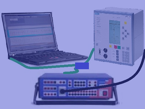
Transformers are valuable equipments that make a major contribution to the supply security of a power system. Optimum design of the transformer protection ensures that any faults that may occur are cleared quickly and possible consequential damage is minimized. Following Protection functions can be used to protect Transformers.

  • ANSI 87T – Differential protection
  • ANSI 87N – Earth-fault differential protection
  • ANSI 50/51 – Definite-time overcurrent-time protection as backup
  • ANSI 67 – Directional Overcurrent
  • ANSI 49 – Thermal overload protection
  • ANSI 46 – Load unbalance protection (negative-sequence protection)
  • ANSI 24 – Overexcitation protection

This test procedure shows how to test a transformer relay with OMICRON Quick CMC module

Directional Overcurrent:

  • Enable the directional overcurrent in the DIGSI.
  • Enter the setting value in the DIGSI.
  • Enter into the Setting Group A.
  • Select the DMT/IDMT Directional Phase/E Overcurrent.
  • Then click Customize.
  • Enter the setting value in the Directional PH/E overcurrent –Setting group A.
  • After entering all the values, Click Ok.

Testing:
1) i) Set the fault phase current value higher than the secondary of the CT ratio. ii) Set the fault phase voltage value lower than the nominal value of PT.
2) In the signals select the fault appeared phase.
3) In the Quantity change the magnitude by Phase.

1) Click the Start button to start.
2) Keep the Phase angle away from the operating zone. If ROC is 45o means then these are the operating region for the different phases.

3) Then press the Increase button as shown in the figure.
4) At the particular point the relay will get a Trip. Note that value.
5) Again keep away from the operating zone, and press the decrease button to find another operating point.
6) Note the Phase angle at which the relay gets tripped.
7) compare those values with the Expected Operating region angle.
8) then repeat this procedure for the remaining two phases.

Our completed Courses: