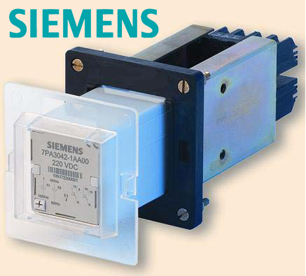
Functional description for TCS relay 7PA30  

RELAY 7PA30*2-1AA00

The 7PA30 relay is designed to supervise the trip circuit for one trip coil of a circuit breaker. The trip circuit wiring is supervised from the positive supply to the negative supply whilst the circuit breaker is open or closed.   

FEATURES

  • The 7PA30 relay monitors the trip supply and correct state of fuses or miniature circuit breakers of the circuit. It will initiate an alarm if the supply voltage falls below the assigned drop-out voltage
  • With the CB in the open and closed position, the 7PA30 supervises:
    • The trip circuit wiring
    • The CB’s trip coil
    • The CB’s 52a and 52b auxiliary contacts

The supervision is done with a small current that flows through the supervision-circuit in series with the trip coil of the circuit breaker. The supervision current is always less than 1.4 mA. This makes the 7PA30 relay suitable for the supervision of circuit breakers with low power consumption down to 4.5 W. Therefore external current limiting resistors are not needed because these resistors are installed inside the 7PA30 TCS relay. 

  • Indicates if the trip coil fails to respond to a trip command. The operation time of the circuit breaker must be less than 150 ms. If it is longer, the 7PA30 will drop off and indicate a circuit failure.
  • Correct operation is shown via:
    – An illuminated green LED.
    – Two potential-free change-over contacts

Both contacts and the LED are in series and therefore synchronized. In normal conditions, the 7PA30 cannot produce an unwanted trip due to the high impedance of its supervision circuit. Measures are taken to avoid a short circuit in the supervision module by integrating a component that melts in this case, avoiding an unwanted operation.

  • The 7PA30 allows a latched protection trip contact (trip contact from a lock-out relay). 

FUNCTIONAL DIAGRAM

The connection diagram below shows the 7PA30 with the complete trip circuit up to the trip coil of the circuit breaker.

The contacts in the diagram above are shown without an auxiliary supply. 

OPERATION

The LED is on and both contacts are in close position (terminal 5-9 and 6-10) whenever the trip circuit is healthy. The supervision is performed under the 4 possible conditions described in the following pages.

  • Supervision with CB closed

The supervision circuit is indicated (via K1, 52a, and the CB coil). K2 is not energized.

Different situations that can occur:
1.- If the trip supply falls below the assigned drop-off voltage, the drop-off voltage control module will detect it. Therefore K5 will drop-off and this will lead to the de-energization of K6 and K3 after 150ms. This will result in a trip circuit supervision alarm.
2.- In case of a broken connection in the supervision circuit, K1 will drop off and this will lead to the de-energization of K6 and K3 after 150ms. This will result in a trip circuit supervision alarm.

  • Supervision during Trip

In this situation, the trip contact of the protection relay and the circuit breaker is closed. The supervision circuit is indicated (via 52a and the CB coil). K1 and K2 are not energized.
The operation time of the CB must be less than 150 ms, in order to avoid the drop-off of the relay. K6 is kept energized with an internal capacitor and therefore also the LED and K3 remain energized. This will avoid an unwanted alarm during operation.

  • Supervision with CB open and protection trip contact closed

Trip contact is still closed in this situation although the CB has already opened. The supervision circuit is indicated (via K2, 52b, and the CB coil). K1 is not energized. 

In this situation, the trip contact can remain closed, e.g. if the protection relay trip contact belongs to a lock-out relay.
In this case, the trip contact remains closed until the trip will be recognized and the lockout relay will be reset.

  • Supervision with CB open

In this situation the trip contact of the protection relay and the circuit breaker is open. The supervision circuit is indicated. K1 and K2 are energized.

The following table resumes the four situations explained before:

SELECTION AND ORDER NUMBER