
Take a look at some of our problem-solving discussions
– If I had transformer YNd11 and want to connect differential Protection is the CT on Primary should connect in Delta and CT on Secondary should connect in Star when I use Numerical relay or not?
– Don’t need to reverse the connection of CT?
– No need to do anything in the numerical relay. Just input the data of your transformer and relay all do the rest. Your CTs star point however must be pointing towards T/F or away from it.
– Anyone can tell me What is the function of CBCT?
– To sense unbalanced current.
– Normal CT is used to measure current in any particular corner phase. CBCT in other words called Core balance CT which is placed over the cable OD or all covering all 3 phase bus or cable. So that it measures the unbalance current in the 3 phase system. Core Balance Current Transformer or CBCT is a ring-type current transformer through the center of which a three-core cable or three single-core cables of a three-phase system passes. This type of current transformer is normally used for earth fault protection for low and medium-voltage systems.
– Secondary CBCT is connected to Earth Fault Relay. During normal operating conditions the vector sum of three-phase current i.e. (Īa + Īb + Īc =0) is zero, therefore, no residual current in the primary will be present. Here residual current means zero-sequence current. Therefore there will not be any flux developed in the CBCT core and hence no current in the secondary circuit of CBCT.
Advantage of Core Balance Current Transformer:
The advantage of using CBCT for earth fault protection is that only one CT core is used instead of three cores as in a conventional system where the secondary winding of three cores is connected residually. Thus the magnetizing current required for the production of a particular secondary current is reduced by one-third which is a great advantage as the sensitivity of protection is increased. Also, the number of secondary turns does not need to be related to the cable-rated current because no secondary current flows under the normal operating conditions as the currents are balanced. This allows the number of secondary turns to be chosen to optimize the effective primary pick-up current. Core Balance Current Transformer is normally mounted over a cable at a point close to the cable gland of the Switchgear. In case cables are already laid in a Switchgear, a physically split core, which is also known as Slip-over type CT, is used.
– What is the meaning of DE and NDE?
– Driving end And the nondriving end.
– The driving end is connected to the turbine.
– The driving end is the coupler side with a moving turbine.
– You mean that the drive end connects to the load.
– Hi everyone, what means p1 and P2? And why it’s different for the same motor?
– P1 is the total induced power to the pump system. P2 is the power coming from the motor (shaft effect). P2 is the nominal power of the motor. The difference between P1 and P2 indicates either: the efficiency of the motor (ηmot.)
– installed distance relay 7SA522 with CT ratio 300/5 and PT 132kv/110v now if I want to change the CT ratio from 300/5 to 600/5 which setting value will be also changed in the relay?
– Required data module manager for the above version.

– I got this type of error while running pcm600.
– Once you manually start the SQL server then Press start.
– If started means now u try PCM.
– Dear reinstall your pcm6002.
– Same error coming, sir
– I have downloaded it from the official website.
– Do u have any hotfix for this version?
– The same problem was with me. I installed pcm2.10 hotfix also.
– Your pc windows10? Please go to PCM’s latest version 2.9 Try to start PCM600 in administrator mode. Then, if it doesn’t work, try re-instal PCM600 and SQL server, and restart the computer.
– Anyone knows what this means I cont In CT?
– The standard value of rated continuous thermal current is the rated primary current.
– Rated continuous thermal current. The continuous rated thermal current is the current which can be permitted to flow.
continuously in the primary winding without the temperature rise exceeding the values stipulated in the standards. Unless otherwise specified it is equal to the rated primary current, i.e. the rating factor is 1.0. In applications where the actual currents are higher than the rated current, a rating factor must be specified. With a rating factor of for instance 1.2, the current transformer must withstand a continuous current of 1.2 times the rated current. The accuracy for metering cores must also be fulfilled at this current. In IEC 61689-2 it is called extended current rating and has standard values of 120%, 150%, and 200% of the rated primary current.
Join our WhatsApp community: https://elec-engg.com/whatsapp-group-for-protection-engineers/
– Does anyone know the right way to connect to the transformer? The inlet Oil of the device is connected to the top or bottom of the transformer? And Why?
– Which equipment is connected?
– You mean I drow the Oil from the bottom of the transformer? Ok, do you know why?
– Inlet to bottom of transformer, Outlet to filtration machine.
– Is connected to the top or bottom of the transformer?
– bottom
– It’s not a filling operation. I want to improve the insulation of oil only is there a difference in the connection way?
– U have to connect the outlet of the filter machine to the top side of the transformer And the inlet of the filter machine should be from the bottom of the transformer.
– By this, the sludges at the bottom of the transformer will get filtered.
– Anyone can explain this unbalance current (reason) in MFM?
– Check the CT wiring for polarity. Then check the parameter in MFM in measurement mode as 3 Phase 3 wire or 4 wire selection.
– Do anyone knows what is the advantage of CS (glass container) in the filtration device?
– Which kind of sequence currents flow during 3ph to ground faults? Does zero or negative seq flow?
– yes zero-sequence.
– is the analog Ammeter on the left side feeding on the same CT input?
– Yes sir left and right side analog meter and same ct.
– Where are we supposed to inject voltage? We can’t inject on the relay side if we want to include a fuse in the circuit.
– You should inject the single-phase voltage in X1:1 & X1:2. R phase fuse will operate.
– Can anyone send the Maintenance checklist of all Substation equipment for weekly, monthly, quarterly, Half-yearly, and yearly 400/220 kV substation?
– What is fictitious resistance? Why it is used in the calculation of peak short circuit current?
– On this P.T 132kv/110 how much rating of MCB will be installed on the secondary side of P.T?
1- transformer without oil (empty) 2- with oil (filled). And Why?
– IR Test is not recommended before oil filling.
– Under the condition of Vaccum, an insulation resistance test is not recommended.
– If I have this connection of batteries, what is the PROBLEM of connecting different voltages, and what is the PROBLEM of connecting the different current batteries?
– What are The PROBLEMs of connecting different voltages of batteries in series or parallel like (12v 8.5A with 6V 8.5A)? And what are the PROBLEMs of connecting different current batteries in series or parallel like (12V 8.5A with 12V 7A)? If you connect different voltage batteries in parallel it lower Voltage battery won’t get charged to produce excess heat Same for the current in series the life of the battery will get degrade
– In which connection are batteries connected in the Battery room?
– Series connection.
– At certain times all batteries will behave lower rated because in series current is always the same. So high rate battery won’t fully change with low rates.
– Does anyone have a high-impedance REF protection wiring diagram by using the same phase CT which is used for differential protection?
– Yes differential phase CT start point neutral using REF protection also.
– Can we make this connection HV to LV to ground in IR TEST without making HV to LV only? Is the first one enough or not?
– Check if any MCB is off or fuse is blown for DC power
– In this nameplate of CB “Resistance of Main Circuit” is it contact Resistance or not
– Is it contact Resistance?
– yes.
– When I test results show 300 micro ohm is that right?
-100 micro ohm✅
– Try changing the positions of connecting cables closer to contact-making points(idea is to minimize the joints). Put the voltage clamp closer to the main contact
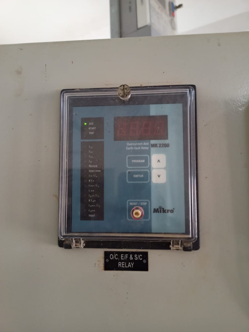
– What is the reason Cap Fuse Fail appears repeatedly?
– When does it appear what you did afterward? Or does it disappear on its own?
– Reset through the reset button
– What is IN derived, IN measured, IN Sensitive in Fault details?
– This relay presently works on 20/26 MVA PTF after a few days this PTF replace with 31.5/40MVA PTF I want to set the file for 31.5/40 MVA PTF
– This relay presently works on 20/26 MVA PTF after a few days this PTF replace with 31.5/40MVA PTF I want the setting file for 31.5/40 MVA PTF
You can join our WhatsApp community too. CLICK
– We plan to inject from LV to HV. The customer is requesting that They are not ready to short in our HV side of the transformer due to some technical issues. So they wanted to short circuit in the upstream side from remote end substations. Now, from the HV side of the transformer connected through the Cable of 3 km appx. We need to know the calculations for the transformer including the cable
– I think it is IEC 60076 for Power Transformers and IEC 60137 for bushings.
– What will be the impact of switching reactors with NGR and without it? Can anyone help
– Please compare both drawings, sf6 breaker top pad which side should come either line or trafo, if so why? If we keep any side what’s the problem will come, if any knows kindly comment on this, thanks in advance
– How to calculate the new 11Kv Capacitor Bank rating & will be installed on 20/26MVA PTF if the total load is recorded at 1100 Amp If 200Kvar Capacitor cells are available?
– Can anyone suggest any good kit for SF6 gas purification and analysis?
– Dilo kit machine data
– Anyone knows this test of 31.5/40MVA Power Transformer (132/11.5) (Dy11)? my question is how to check these results How to test thermal overload protection and unbalanced overload protection?
– If u know the percentage impedance and Hv side voltages at optic tap 1,12,23 Let me assume tap 12 is normal
– S it is SC TEST, RESULT ok
– We can calculate and ensure she current at a particular tap
– For thermal overload protection make sure that the current thermal state is 0% and inject 3ph current above your settings current and observe the thermal level in your relay, make sure the alarm at your set value is coming and it will trip at 100% thermal state. Record the tripping time and compare it with the calculated tripping time ( you can find it in the manual)
– For NPS either u can use a single-phase injection then 1/3 of your injected current will flow as negative sequence current. Observe that current in the relay. Do the same as mentioned in thermal protection Or u can use the Symmetric component injection method which is available in most of the kits.
– Normally what value of Voltage difference is kept in synchronization relay 500kV lines?
– We have 2 sets of distance relays set1 and set2 with respective auto recloser AR1 and AR2. A single auto recloser AR1 or AR2 on a 500kV transmission line recloses both BxQ1 and BxQ3. If line trips on temporary fault and AR1 auto reclosed successfully the first time and soon after during reclaim time of AR second fault appears online then AR1 get blocked as per scheme and fault is declared permanent. But at the same time, AR2 gets initiated by a set 2 distance relay and it reclosed the line on permanent fault. This is a single-shot scheme.
– How to monitor bits in Real-time Mode? I have already connected Easergy studio with a relay but it always gives a Demo mode option.
– you need to make the connection from the PSL editor. I have connected my relay with Easergy studio
– It does not mean that you made the right connection from the PSL editor.
– All good but bit monitoring is not enabled in real mode. make the com setup properly and open the connection. That is different, for DDB monitoring you need to open a connection from the PSL editor with the right settings. it means you did not have the right connection.
– Hello. I’m using ABB RTU in a substation setup. One of the logical nodes (GE L90) shows RTU inoperable. Where could I have possibly gone wrong? Would this affect the transmitting of signals to the RTU from L90?
– what protocol is being used? 61850?
– Yes 61850
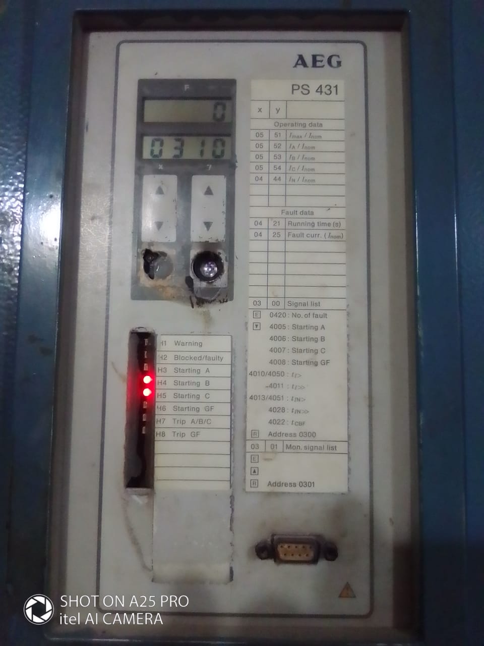
– What is the problem with this relay The triggered LED continues blinking.
– What is the meaning of DR?
– Disturbance recorder
You can join our WhatsApp community too, CLICK
– How many percent of OC and of setting in this relay ct ratio in 300/1amp? Is it possible to configure REF615 to be a differential relay?
– yes, if we use it as high impedance protection.
– How to calculate CT size for motor hp, And REF615 protection relay how setting and conditions?
– I mean, all the CTs outside of the relay can be grouped and connected and the total current goes to the EF winding included in the REF615. However, this is only suitable for high-impedance protection
– Ok 1- Make Sure that LED 7 is Not latched. 2- In case LED7 is Not Latched check all logic connects to LED 7 Because RDRE1 cannot keep LED7 on continuous. 3- if LED7 is latched, one of the BI is true.
– can we use the RED 670 relay instead of RET 650 for Transformer differential protection?
– No RED relay for line differential, uses two boxes- master-slave. So you can’t use it.
– This is our 132kc circuit distance relay, How to calculate the setting of this relay? The line is loaded above 50amper in 132kv line distance relay is operated what is the reason?
– Can anybody tell why the second functional block input is not matching the output?
– Input to the second functional block is 68.52 but the output is 58. also input is changing but output remains constant at 58. Check the parameters of this block.
– Parameter setting is the same for both the functional blocks. The first functional block is working fine but the output of the second block remains constant at 58. Do this interchange the inputs, upload again do the monitoring. This will make sure the function block is ok.
– Yes make a sure dead band and limit parameters. But output remains constant at 58 irrespective of input
– Present input is 68.19, but the output is 58. Did u do this?
– After interchange also, out remain 58 only. What’s your relay type?
– ABB REC670 BCU
– Check the output of this module connected to RANG_Xp.

Be a part of our problem-solving discussions: https://elec-engg.com/whatsapp-group-for-protection-engineers/
Our completed Courses:
- IEC 61850 Configurator Training (4 Hrs)
- DIGSI 4 Offline Video Training (3 Hrs)
- DIGSI 5 Offline Video Training (7 Hrs)
- ETAP VIDEO Training (5.5)
- PSCAD Video Training (4 Hrs)
- PCM 600 Video Training (4 Hrs)
- MiCOM Relays Training Package (4 Hrs)
- Testing and Commissioning of Protective Relays