
Join the problem-solving WhatsApp group to get your answer: https://elec-engg.com/whatsapp-group-for-protection-engineers/
– There was a 5 MVA newly installed isolation transformer having ABB make REF615 relay connected to it.
The problem was whenever the transformer was charged Relay SEF protection operated. When DR files were investigated, there was a huge unbalance current flowing during the charging of the transformer for 5 sec. Since there was a residual connection of SEF (Io setting was 10% FLC) so unbalanced current flow is neutral. Therefore recommendation was to increase the timing of SEF to 6 sec. Is this recommendation correct?
– Is SEF connected to the residual connection? Also, ask them to block inrush current. You can block SEF for the first 5 sec from transformer charging then you can unblock it to avoid nuisance tripping due to unbalance inrush current, making 6 sec is not correct as you are permanently increasing the operating time of SEF By SEF u mean to stand by earth fault or sensitive earth fault?
– Stand by earth fault. Stand by earth fault by definition and philosophy should be connected to neutral CT. What is the difference between a normal earth fault and SEF if u connect it to a residual connection of phase CT?
I am never in favor of giving 10% pickup to a residual connected earth fault relay. Had it been a SEF connected to neutral CT 6s delay is ok. SEF is the last level of tripping for an uncleared earth fault and hence this time delay is ok. If NGR is present, you need to check the NGR current withstand time and make sure that the delay is less than this. Generally NGR fault current withstand time is 10s, But, by the name itself don’t u think that must be kept sensitive to residual connection pickup setting?
– To detect fault close to the neutral point..that too for impedance grounded system Stand by earth fault is not sensitive earth fault.
– The main idea behind using SBEF is that, in the DY transformer, there is no backup protection available for the Y-side earth fault relay. SBEF provides that backup protection. To give a sensitive setting to relay, u need to consider the error n CT dynamic characteristics into account. There is a very interesting section in NPAG that explains this.
– If any low setting can be given to a residual connected earth fault relay, then y do u think we use CBCT?
U have to be pretty sure about your CT dynamic response before giving a low setting to a residual connected earth fault relay.
– But SEF will be used at the neutral of the transformer, right? Do we still have to consider CT dynamic characteristics if ALF is ok?
But in this case, they have not used neutral CT. My understanding is for a residual connection we generally go with a 10-30% of CT ratio as a pickup. To protect the transformer winding which is not converted by the residual connection we will go for SEF at neutral and keep pickup sensitive.
– I presume here they have SEF means they must be connected to the neutral of the transformer. Even if it is not the case they can increase the pickup of the relay momentarily using the inrush detection function instead of increasing the TOP is what I feel.
– In which conditions NGT secondary voltage should be increased above 500 V instead of 240 V?
– See As per the manual they assumed their secondary is 500V but over NGT is 240V so according to that u need to use a resistor to 0.2 ohms to get the stable and accurate measurement for the earth fault. it depends on ur NGT secondary voltage. In your Case for the Transformer Protection, u didn’t have Differential Protection in Any new transformer or Running Transformer if u Energize for the first time or you Energize after Shutdown the windings will conduct a minimum current that we called an Inrush current at the time we need some protection to block this inrush so in ur case u didn’t have differential protection only u have Earth fault so what they recommend for 6s is ok but After energized it should return to 5s.
– Actually, there was an existing 13800/240V. NGT is connected to a generator. For some reason, it requires redesigning the resistor which came to around 0.256ohm but the problem is it was asked to increase the NGT secondary voltage giving reference to the manual. Are there any standards for this?
– if there is 240v in your design then you should correct it according to NGT if u need it as per the manual then ur NGT should be 500V no PBS for 240V u can use as mentioned 0.256 ohms.
– as I know I didn’t come to a cross standard it always depends on our System voltage. But the relay ABB REF615 has an inrush-blocking feature in the current module I guess. it’s enabled.
– NO REF only has Feeder protection, Current, and Earth fault.
– the function is off.
– Yes. when it is enabled it will block the tripping. u need to configure the Function block in ur IED, But keep it at 10% it will not exceed more than that I think Remove Hindi Type Vv Add Chandan Kumar Singh India added J 1000 Sys 95.
What is the blown-out time for the SFU fuse of 60/100 A? Is it 20ms Or even less?
– If fuse and relay were to co- originate What time discrimination should be given between SFU fuse (100A) and EM relay (CAG 14)?

Dear engineers, you can share your related issues in our discussion groups to find out the solutions. Please text on WhatsApp to join: https://elec-engg.com/whatsapp-group-for-protection-engineers/
– A single-phase 105MVA, 400/220/33kv single-phase ICT has been replaced in a three-phase delta star connected unit, and above is the issue when they are charged? Please share ur views or possible reasons for this what is the status of voltages? Are they balanced?
-If there is unbalance in the phase then there’ll be voltage generated in the open delta circuit.
– They are balanced it is working with the spare transformer the issue is when they are replaced with the new one
Better to simulate the scenario in software and see the results.
– Are you trying to do it online or offline? If online, then PCM will retrieve the model automatically from the front port. If offline, then recheck the complete model which you want to configure. The yellow mark shows hardware items invalid with the complete model. When I’m trying to do this offline then I’m not able to put the correct code in the yellow section.
– Online means the PCM will retrieve the code from the relay itself, Check whether the relay is showing online or offline in PCM. May the communication have an issue. The best is to create a complete relay connection again. I prefer to reinstall the Connectivity Package file of RET615 again With its current software version which is in the relay. I installed the REF615 recently with the PCM 2.0 version. It worked.
– How does relay Sensing CT saturation? How could we Protect from CT saturation? If CT saturation Occurs, what’s the Real-time status of the Diff relay? How could we test the CT saturation scenarios in another make relay?
– Mostly in-bus bar differential relay CT saturation is taken care of by an inbuilt algorithm/program. when we open one secondary of one phase CT. tripping gets a block Also, there is another philosophy of bus zone and check zone where CT saturation or CT secondary problem is taken care of by comparing both current statuses of two cores.
High resistive fault can take place at any distance ..it may be zone 1, zone 2, or zone 3. So we are maintaining the highest resistive reach for all zones.
– Anyone aware most of Micom P44X relay resistive reach are the same for phase and ground?R3G, R2G, R1G -33 ohm
R3P, R2P, R1P – 25 ohms. Why are these values are same in most of the Micom settings?
– As per the theory in the p44× handbook of Alstom maximum resistive, reach for ground fault is 80 % and for phase, the fault is 60 %. The faulty resistance is calculated by expecting a 120 % rise in current and a 20% drop in-phase voltage.
– Resistive ph reaches 60 percent of maximum load impedance and ground reach is 80 percent of load impedance for Zone 3 I think, Again Zone 2 resistive reaches are taken as 80 Of zone 3 resistive reaches I guess. I think 15 percent drop in-phase voltage, And 1.5 times rise in current But taking voltage 0.85pu and current 1.5 times of conductor capacity either for zebra/ panther taking cos angle in emergency loading Zloadmin
R3G-80% of Zloadmin
R3P – 60% of Zloadmin
– We were not able to achieve a resistive reach of 33 ohms for ground and 25 ohms for phase. So On what basis French are proposing these settings?
– As per my calculation R=V/I
V=0.8 ×63.5 v
I=1.2 A
R=(0.8×63.5 )/1.2
Rg=0.8 R=33 ohms
Rp=0.6R=25 ohms
– But the concern is R=V/I * cos phi. The calculation is given in the Alstom P44x book.
– An 11Kv, 2.2MW synchronous motor tripped on-field failure. As per customer excitation is healthy. What could be the possibilities of a field fail trip? It’s running for 1 year. LOE will operate when the impedance trajectory passes the offset mho scheme. This tripping seems to be due to transient swings or low-frequency disturbances. Do u have the Comtrade file? And settings of the relay
– Comtrade file customer can’t able to retrieve as he does not have a laptop and expertise to retrieve data. Settings I will provide
– One 20 MVA transformer has frequent trippings by REF on the LV side. What will be the probable reason?
– LV side field CT and NCT have the same ratio of 600/1. The stabilizing resistor value for a through-fault current needs to be checked. The polarity of the lv neutral ref ct may be reversed. The s1 and s2 are to be reversed and connected and then checked. As CT3 is measuring fault current similar to neutral current there may be a single-phase fault at the remote outside of the zone.
– Have you observed any other fault or pickup in lines?
– That REF operates when there is a 33kv feeder tripped.
– Wiring diagram Fault angle for both LV CT ILN and LV CT IL3 are the same and the magnitude is also similar
– Is it tripping during charging or in running? This proves there is no internal fault.
– Yes. once check the pre-fault current angle of IL2 and IL3 one is -142 & -108 deg.
– One 20 MVA transformer has frequent trippings by REF on the LV side. What will be the probable reason?
– LV side field CT and NCT have the same ratio of 600/1. It’s the problem
– Is it connected to the local grid? Any external system trip during that time?
– Once checked with polarity only I doubt the polarity of IL3, While posting such cases it is useful to the members of a brief note on trips is given and details of fault records are mentioned Or check the relay setting and test if for any commissioning mistakes
Eee Deepak Kindly adds in protection relay and IEC 61850 India: Whenever There is a fault on the 33kV side transformer is tripping on the REF fault
– 33Kv is HV or lb. I presume that it is D/y TRX with LV 33Kv. Right?
– Yes
– It is a polarity issue of CT. If u see in this screenshot the magnitude of current in IL3 and neutral is almost the same, which confirms there is an external fault (resistive grounded system). Then if you observe the angle there are the same but if there is an external fault it must be in the opposite direction. So if one is -108Deg the other should be 72Deg. So I feel polarity should be checked once by doing a stability test of the transformer.
– Kindly share your troubleshooting story, practical facing issues, any new R&D topic, etc. We will share the documents and will try to resolve the issues.
These groups are very useful for serving engineers in solving problems they face, updating knowledge, and also helping co-members if they have solved similar problems earlier. For senior engineers who are not in service to share their experience and be in touch with the subject. you can also join, by CLICK
– I was carrying out load flow analysis on a simple network With the shown parameters. However, the load flow parameters do not seem to agree with the expected values. Can anyone guide me on where can be the probable mistake?
– Can you capture the transformer’s input data modeling window?
– I think the cable parameters I have put wrongly. Why generator is being overloaded?
– it is a slack bus But it should come near to 6 MW including losses, Generator is rated at 5MW, but it is delivering 24 MW
– check cable parameters maybe the extra MW is getting lost
– Load is of 4 mva only With 0.85 pf, But it is drawing 15 MW.
– Can you capture the load input data modeling window?
– It is erroneous but I am unable to spot where it went wrong.
– Can you once increase the transformer’s capacity and rerun the load flow?
– In load parameters, check the operating load data.
– actually, it was some absurd values over there. However, I have corrected and re-run it.
– Results are the same When re-opening the window. Previous garbage values are coming. How to make my data save sir?
– I will build the same network After correction, can you send those results and input data? Because the cable will not draw active power. The transformer is overloaded And the load element is drawing more than its rated capacity. It has to be checked first.
– also I want to model a simple transmission line With a 132kV panther conductor. Is that possible here? Below check the operating load. Why cable will not draw reactive power?
– You can model your lines and cables If their parameters are known.
– It is getting changed after running the load flow
– Make the operating load 4 MW And re-run load flow, Cable will draw reactive power and there will be an active power drop.
– it’s already done And is a very high-voltage cable.
– Let me try with a high load. So that the overvoltage can be compensated If the voltage is 132 kV.
– Then try to replace an overhead transmission line in place of a cable. There would be a capacitive effect too.
– Yes Correct, But the distance is only 50 km
– Transformer secondary winding – delta?
– But as the load is less capacitive effect is substantial
– It’s too high. It’s simply a fixed load of 4 MW
– I think ur load flow is not converging
– how do debug the mistake?
Yes, just run the short circuit once. Also, no error reports coming. I have not put the short circuit parameters. Once open the branch reports power flow You run a short circuit fault current ll not appear
– Check the branch node in the manager
– Load is drawing this much. And not the 4MW. PLEASE CHECK THE TWO SNAPSHOTS
– Capacitive effect is dependent on voltage, and ETAP doesn’t show a pop-up for convergence, Please someone tell me how to change and save operating load data correctly.
– Please check the Bus Voltage
– Operating load is automatically generated after load flow analysis. The operating Load can be updated from the Load Flow Study Case Editor. The operating load option is available if your ETAP key has the online (ETAP Real-Time) feature. When the operating load box is checked in the load flow study case editor, the calculation results are updated to sources, loads, and buses to be utilized as input for later studies. If your ETAP key does not have the online feature, you can see the operating P and Q data in the element editor; however, this data cannot be used in a later study.

– I am doing a system study for the expansion of the existing plant. During short circuit studies, the bus bar rating exceeds 50kA. Please suggest a solution needed to increase the bus bar size or any other fault current reduction devices on the LV side at O.415 kV level.
– Selecting the transformers with high percentage impedance Or verifying the availability of laying another bus in parallel with the existing bus, Keeping the spacing clearances in consideration. Hence it is the existing transformer increasing percentage impedance is not possible now and only one transformer is in the system.
– What are the transformers through fault current? Spitting of the main buses may also be done for lowering fault levels.
– 43kA. It’s not only about changing the bus bar. You should also check the associated switchgear rating. Busbar short circuit current withstanding capacity of >50kA is recommended. That’s why I need a cost-effective solution to reduce fault currents.
– What is the available fault MVA given at your source point of the network?
– Source fault current not given I have considered 25 kA it is HT side bus fault current.
– You considered 25kA at what voltage level?
– If you can know the details of upstream transformers at 22kV, You can calculate the fault of those Transformers and arrive at the correct value. Selection of 50kA rated switchgear for 3 secs withstanding time, would give you higher short circuit current withstanding capacity for 1 sec And the fault isolation (relaying action) will be done in below 1 sec.
– Is there any ACB or current-limiting devices to reduce the fault current at the LV side like reactors?
– I don’t know of them.
Join our community on WhatsApp: https://elec-engg.com/whatsapp-group-for-protection-engineers/
– The originator of the post didn’t give the details of the expansion proposed. During chatting single-line diagram(SLD) was given not at the beginning. Expansion can be either power generation or motor loads etc., As per the SLD source short circuit MVA is 165MVA. It has to be confirmed whether it is the same now or if there is any increase. Circuit breakers CB1, 2, and CB 203 are to be obtained. Buses’ short circuit ratings are also to be gathered. Proposed expansion SLD to be added to existing SLD. As per obtained data, it is to be verified whether existing breakers breaking capacities are having any margin or not. It is to be noted that when we are adding generation to existing buses we have to verify existing breakers’ breaking capacity, as it will affect short circuit currents magnitudes.
– Expansion in the load side and transformer rating is 2MVA. I have also checked that the source fault MVA was reduced to 1OKA the fault current still exceeded 50 kA On the LV side. So the requirement is to reduce the fault current at the LV side of the transformer.
– Your source fault level is 4.33kA at a 22kV level. What are your transformer impedance and vector group?
– 5.87 percent, Dyn11. Your 0.415Kv bus fault level is 47.393kA considering the infinite source at the primary of your transformer. But the fault at the primary of your TRX is only 4.33kA. Thumb rule to calculate fault current at l.v terminals of the TRX. (considering infinite source at primary) is TRX. FLA(l.v)/ TRX. per unit impedance. Here it is 2782/ 0.0587 = 47.393kA.
– Yes you are right we need to consider the fault current from the load side it is almost 11 kA. It will increase the total IK value to near 60 kA
– It’s the through fault current of a transformer, which will have a negligible change in the calculated fault current w.r.t increasing source fault MVA.
– We have considered source fault at 22 kV level is 25kA
– So it will cause the fault current at transformer sec to nearly 44 KA and also as per IEC 60909 We need to consider the 1.05 c factor. What is that 11kA where did you get it? In your SLD source, MVA (22kv level) is 165 MVA meaning 4.33kA then why 25kA? The worst case is the consideration of infinity source at primary With that your l.v fault level is calculated and is 47.393. I informed your source fault level is not that much.
– Source fault MVA IS 1002.165 MVA S. Assumption on this available fault level is based on? Incoming breaker Isc?
– Yes
– The selection of breaker rating will always be higher than the calculated value. In this methodology, the calculated will be much more, while in actuality it will be lower than your calculated value.
– Please check the correct source fault level. Do you want to replace the TRX with a 2.5 MVA capacity? In SLD it is 2MVA.
– As long as your TRX capacity is 2MVA, the fault level will not be more than 47.393. If you consider 25kA as a fault level then you cannot get the actual fault level moreover fault level at incomer also should be less than 80% of the breaker rating. you can get the actual fault level from the utility. In studies, accurate data can only give accurate results so don’t assume any major data user x: Deepak this 25kA worked out from SLD. Because of the closeness of the symbol and figure I mistook it for 165. It is 1002.165 M.V.A. At a 22Kv voltage level, it works out to be around 25kA. This is a simple circuit for short ckt studies and hence manual calculation is not difficult. If one wants to review existing breakers and buses’ short circuit capabilities HV side source data is necessary. L.v side, the first rough calculation can be done assuming TRX H.V side fault level infinity. If it is more than the existing breaker rupturing capacity then finer calculations are necessary. The originator has to confirm whether expansion requires TRX. capacity enhancement or not.
– It is concluded from the load flow study that a transformer capacity of 2MVA is enough for expansion load so the problem is in the short circuit study. The transformer SC contribution itself is nearly 44 kA and the fault current from the load side is nearly 15 kA so the requirement is faulted current limiter at the LT side.
– I don’t think that any current limiter is needed if you keep the actual fault level it doesn’t cross 50kA
– Definitely
– Please fill in the missing information.
– In short circuit studies it is important to furnish details of fault current capabilities of breakers and bus bars. In a spreadsheet, I left some cells with? mark. Please provide that information then we can review it in a better way.

– Which software is suitable for preparing the electrical drawing?
– Auto-CAD is the worldwide used software for any type of drawing. However, all big companies have their software.
– but it’s not supported in window -8.
– It will. You have to use licensed software. If using a licensed one then contact AutoCAD engineers for proper installation. Also, check the compatibility of Autocad along with the service pack and type of bit of operating system. Window 8 means Cad 14,15 and 16 will support. I am not sure above this will support it or not. The best practice changes the operating system to either lower than 8 or higher. Coz Windows 8 has lots of issues.
– I will not suggest pirated software. But if you are using then need to install it the incorrect way with a proper key generated by Keygen. Actually, the operating system i.e, Windows 8, failed to support many softwares and was accepted and withdrawn back very soon by Microsoft.
Yes. Better to upgrade to 10
– sizing calculation for High resistance grounding for 4.16 kV system. Please provide the calculation format. Please give some details, Your question is very vague. You would have given a simple SLD of the scheme.
– You need NGR sizing calculation?
– I need a high resistance grounding calculation format this is for a medium voltage system
– NGR Calculation?
– for a 4.16 kV System Neutral Grounding Resistor rated at 400 A. The line to Neutral Voltage will be 4.16 kV /√(3) = 2400 V. The required resistance will be 2400 / 400 = 6 Ohms.
– this is for the low resistance gd rounding calculation for the high resistance grounding system current should be less than 10AMPS.
– Why is high resistance grounding for a 4.16kv distribution system? is it the requirement of project specification?
– On what basis it is recommended? Normally for this voltage system, low resistance grounding is used.
– it is recommended by IEEE 142 and IEEE transaction paper, it is mentioned like following 2.4 and 4.16 kV. The primary reasons for this trend can be briefly recounted as follows.
1) A feeder circuit is not automatically tripped on the occurrence of the first line-to-ground fault; thus the continuity
of service is maintained.
2) The fault can be detected, and its location pinpointed while the system remains energized so that an orderly shutdown for maintenance can be scheduled.
3) The buildup of destructive overvoltages caused by restriking (or spitting) line-to-ground faults is prevented.
– You have any project to be executed with this grounding system. Probably it is about the advantages of high resistance grounding. System grounding itself big subject in Elect engineering. As far as my knowledge goes, after so many discussions now generally used grounding dust are for 415 V system (LV) solid grounding, medium voltages low resistance grounding, and in high voltage systems TRXs.
– I have not worked for the high resistance grounding till now sir, this first time. neutrals solid grounding system is used. In the case of high capacity, generators limit currents in the case of core faults High resistance grounding is used. Depending on the system grounding protection has to be chosen. In some cases, equipment insulation has to be chosen.
– in our project, they asking high resistance grounding for the 4.16kV System.
– You have any projects on hand? If so give details and it’s complete SLD. Protection especially E/f protection has to suit it.
– It is a design stage sir hereafter only we need to identify protection based on our conclusion
– What is your production process and what are loads connected to the 4.16Kv system?
– It is an air blower sir connected at 4.16 kV
– Unless there is some strong reason this H.R grounding is selected. Because of cost and other reasons distribution of TRX earthing is used for gen. neutral earthing
– There is TRX 4.16kv winding capacitance connecting bus duct or cable capacitance if any surge arrestors etc are required to size sec. the resistance that will be connected in secondary earthing distribution TRX.
– I feel resistance grounding is required only when their high SLG fault current is above 80% of breaker capacity in LV swbd. Breaker-rated normal current rating selected based on the load connected. Basic considerations in distribution grounding systems are Economics, Control of overvoltages, control of fault current magnitude, and ground fault protection.
– I think that the place where ground faults are common, and place where grounding potentials play a significant role, and place where ground conductors are exposed to humans will require high resistance grounding.
– Can you give an example of such places or applications that are being implemented?
– Underground mines, airports, data centers, etc
– As far underground coal mines are concerned there is a blower motor, lift, and water pump motors with the lightning system all 11/0.433kv distribution system there is solid ground neutral. As far as the airport is concerned you can check in the Chennai airport distribution network all neutrals are solidly ground You can find resistance grounding in 33/6.6 kv TRX where 6.6kv swbd has motors that increase the fault current.
– But there could be resistance grounding in special cases.
– What type of plant is it? It is a sewage plant?
– In IEEE 142 they mention high resistance can be used in the 2.4 and 4.16 kV. How much SLG current you are getting wid all motor contributions?
– What Saieesh referring to are the isokeraunic areas where there will be many lightning strokes. In such areas recommendation is to use an overhead shield wire for direct stroke lightning protection. Another ethos of providing lightning protection that is affected by the type of grounding is the use of surge arrestors installed on each Conductor at intervals. The voltage rating of the arrestor is directly rated to the effectiveness of grounding employed on the system. That means system grounding is the designer’s choice depending on industry process requirements and other factors.
– In Hyderabad GMR’s RGI Airport, all high voltage neutrals are of resistive grounding.
– Standard says H.R’s grounding system is occasionally used on 2.4 or 4.16Kv systems. It is nowadays used for medium and high-capacity generators neutral earthing. It can be used where service continuity is required. I saw a case where cables failed because of wrong calculation of charging currents thereby secondary resistance of the H.R earthing system.t is as per.
– After analyzing earlier problems experienced generally followed earthing systems I posted. But some process industries depending on process requirements adopt other than generally adopted ones. For example unearthed systems. The system designers will consider all the factors including protection. Earlier some Medium voltage systems used to have unearthed systems but later low resistance earthing system was followed. IEEE standard discusses different neutral earthing systems in C62.92 with different parts and different equipment.
Join our community on WhatsApp: https://elec-engg.com/whatsapp-group-for-protection-engineers/
– Four quadrant power flows. Electrical system power flows can be represented in a Cartesian coordinate system. Active power plotting on the x-axis and reactive power on the y-axis. During steady-state operation synchronous generator operates in the Ist quadrant delivering active and reactive powers into the grid, and in the IVth quadrant delivering active power and receiving reactive power. Similarly synchronous motor operates in the IInd and IIIrd quadrants. Now it is used in EHV transmission system power measurements. Voltage and current signals are digitized and their fundamental components are evaluated. Using these components and phase angle, the active and reactive power in four quadrants was computed. To take care of variable power tariffs, multiplication factors are changed depending on frequency and voltage. Active power is drawn over and above schedule when the frequency is low and the same for reactive power is drawn when the voltage is low.
– Can anyone give me line parameters of 33kV and 66kV Coyote conductor and 33kV Rabbit conductor (Rp, Xp, Bp, Ro, Xo, and Bo) values
– 2×20 Mva TRF at Gss kudra in Bsptcl are tripping simultaneously on differential fault. Both the TRF are separated on 33 kv Main bus. Above is the fault record of today’s tripping. Any suggestions?
– Can you post SLD and brief history?
– In brief, the substation is radially charged by a single source the 132 kv bus is single and feeds both the trfs but on the 33 kv side the high-level switch is opened so they are feeding 33 kv feeders separately. The trfs are in service for more than 10 years now and have Ret 670 as a differential relay. A few more tripping records are as follows 👇🏻
Tripping of both transformers at the same time on differential protection could be due to a fault on remote GSS.
The fault magnitude is around 15A. I feel the slope 2 settings could be checked once by simulating through fault current.
– Kindly share the Trans. nameplate details, and RET setting file with the fault MVA of the 132kv bus.
– Both the relays might have D.C supply from a common source. Please check common area wiring including fuses or mcbs
– From the data, it is observed that the transformer differential has seen ground fault
– It may happen the ground fault would be outside the differential zone. Please check if zero sequence compensation is provided in the differential relay for the star side
– These two trxs are not in parallel. LV fault current magnitudes are not high as those of HV. Therefore these are not the fault of Mal operations. Both relays operate simultaneously except in one trip data given. I talked to the originator of the posting and asked to check the common D.C ckt wiring of these relays.
– Anyone has fiber optic cable commutation knowledge? I want a confirmation, of whether I can use a multimode FO cable with single-mode relays or not. If yes, what are the impacts on communication? For Overcurrent & Earth Fault coordination, whether the following points need to be considered?
1) stabilizing resistance calculation for REF, EF & sensitive E/F.
2) Opening of one pole.
3) E/F mal-operation during motor starting.
4) sensitive E/F (CVCT-based) pickup & time should be calculated.
– One 20mw generator tripped on 51N during synchronizing with the grid. What could be the reason?
– What is the 51N Protection, pick-up magnitude?
– IDMT E/F ( Ansi code 51N)
– Current settings applied in that protection?
– Can I know the magnitude of the fault current?
– 0.97 Amp secondary (CT: 100/1 connected to the neutral side of the generator)
– What is the voltage,?
-Then there may be some high resistive fault During synchronization.
– Tripping immediate during sync. Earlier information is that it first tripped while in service. Afterward tripping while synchronizing. Hope that it is correct. As they can buildup voltage, let them measure Neutral C.T current after building rated voltage and before synchronizing with clip-on meter hooking in C.T wire.
– Relay terminal nos. 52,53 for neutral c.t connection.
What is the magnitude recorded in the fault event log?
– If there is a fault in the generator then it should trip even before synchronization. But it is tripping the moment the generator is connected to the grid. So the problem might be in the grid but there will be a delta star transformer between the generator and the grid so the earth fault in the grid will not be seen as an earth fault on the generator side but will be seen as a ph fault. So the given input may not sufficient as we need to know what is the type of earth and if there any other earth fault protection. Will the unbalance in the grid cause such tripping in the generator, due to lower magnitude compared to the grid settings?
– Unbalance is not the earth-fault
– Does unbalance result in the current flow in neutral?
– Earlier we faced this type of problem. During switching on the BFP the unit is tripping on 95% earth fault protection. Even we are having UAT. The problem is a loose connection at the HV side of UAT. due to BFP starting currents because of a loose connection at the HV side of UAT power termination at one phase causing a flashover. Then the same is rectified. So I am suspecting these types of problems may be there. In our case, the generating voltage level is 11 kV and BFP is 6.6 kV. The generator capacity is 50 MW. Generator Neutral earthing is with NGT.
– Can someone tell me why the motor behaves as a constant impedance load while starting and as a constant power load while running?
– What is the minimum loading of the transformer in one of my projects it is loading only 13%. If this causes any problem is it ok?
– kindly refer to the equivalent circuit diagram of the motor. I think that can be explained
– Just one doubt. Regarding the star-delta transformer, if there is a single line to ground fault on the secondary side of the transformer is it possible that the earth fault relay will not see any current?
– For a star Delta transformer. L g fault on the star side will be seen as L L fault on the Delta side. If no grounding TRF is on the delta side no earth fault will rise, But the Hv star side will operate on the earth fault.
– No I was asking for earth fault current on the lv side delta configuration
– Yes. On the LV side, the earth fault relay will not operate
– Y is it so?
– Line to ground fault on the star side will be reflected as the line-to-line fault on the Delta side. Zero seq currents will not flow on the Delta side. Zero sequence y it will not flow on the delta side?
– How will it flow if no ground connection is there?
– My question was there is a single line to ground fault in the delta side secondary so if the relay there for earth fault protection? Then also it will not trip because the current will not have any return path. why it is not possible to see the earth fault current by relay on the delta side?
– Because there is no return earth path in delta formation. For the earth fault current to flow there should be an earth current return connection. Auto Transformers or Star winding mostly we have open Delta which reduces or circulates fault current. When an earth fault occurs star side phase that reflected current circulates internally among phase windings and will not enter inline terminals of delta-connected windings. Hence it will not be detected. For that open delta, protection is one solution.
– Can anyone give me the actual value of the current magnitude and time of tripping with this setting with CT 600/5 in the 33KV incoming line?
– If 450 amps come in primary means it will trip @ 100 ms
– Anybody knows how to transfer real-time values of MW, MVAr, kV, and Amp from siemens 7UM6 to DCS?
– 7UM62 and DCS both support the Modbus communication protocol.
Join our groups on WhatsApp: https://elec-engg.com/whatsapp-group-for-protection-engineers/
– For 3 phase fault current in a transformer can we calculate a single line to a ground fault? And how can we convert that into per-unit values?
– Answer is NO. since in a transformer sequence impedances are not the same with each. If current =V/Zp (Zp = positive seq impedance) Then for unbalanced fault Current= V/(Zp+ Zn + Z0).
– For a transformer seq impedances are not the same
– Yeah these are the sequence impedance formulas Positive and negative are the same Only the zero sequence is different
– How to convert fault current in p.u then?
– Unbalanced fault calculation is a tedious job If you want to do it by hand Coz generally converts impedance in p.u. The best method is to calculate the entire thing into PU And then multiply it with the base value to get the current. The reverse is not a general mathematical practice
– Is there any method to convert current in p.u also?
– Why you will express your current in PU?
– Calculate that in PU first and then give the actual value
– 46 negative sequence, 79 autos reclose, 37 undercurrent
– How to calculate the operating fwd & rev region angle for directional earth fault protection in GE L90 relay if current polarization is used, ECA-60 deg lag, FWD limit angle – 80 deg?
– For the current polarization method, if anyone knows please let me know the explanations.
– This method is used in a power transformer if ct is neutral or tertiary.
– yes you are right it’s for a power transformer that steps up from generator voltage…Reference Ig CT we took from neutral of this trafo.
– It is grounded, right?
– yes
– Is there any other method to limit the fault current other than NGR? Kindly note that NGR will not limit the fault current (It limits only the Single Line to ground fault Current).
– NGT is also possible. U can use a series reactor and Is limiter even. If it is a greenfield project we can limit fault current with transformer impedance at the engineering stage.
– Whichever method is cost-effective and efficient? Is limiter OR Introducing Transdermal?
– What is meant by LDCM in line differential relay?
– line differential communication module
– why have to use the high impedance option for REF protection and why not in normal transformer differential?
– If we use the low impedance method to REF what would happen?
– If a CT got saturated in that case the current will not be balanced hence it will try to through the instrument And which will make unnecessary tipping and also protect the Protective relay High impedance option use.
– Ok then Why not use the high impedance method in a normal TRF differential?
– See the normal transformer differential and compare the current between the 2 windings of the same phase. So if there is an internal fault, in that case, the current will not be the same hence it will trip But if a through fault occurs in that case the same current will flow through the high voltage as well as low voltage side, In this condition, the relay should not trip as it is an outside fault! The same thing is for REF as it is a zone protection scheme! In the case of the ref, the relay has to be more sensitive as the relay trips in a very low current! That is why REF uses a high-impedance scheme. In normal differential protection, the allowable current is much higher compared to REF the setting of REF is usually 5% in most cases!
– Nothing will happen. We have much low impedance REF protection across the globe working fine
– Which type of differential is good for the Motor? High Impedance differential or Biased Differential? What is the condition to choose the type of differential?
– Both high impedance and biased differential could be used. The advantage/disadvantage of the biased differential is
- They can operate by having CTs with lower knee point
- They are not as sensitive as high impedance
- They can compensate for inaccurate or saturated CTs
- Their relay is of low impedance type
- Their circuit is a bit complex compared to the high-impedance type
- Their relay setting is less complex compared to the high-impedance type
In my view, you should go with high impedance differential protection as it is highly sensitive.
You can join our problem-solving discussion groups too, text on WhatsApp: https://elec-engg.com/whatsapp-group-for-protection-engineers/
– Whenever an SLG fault at the star-connected secondary of the transformation, in only one phase fault current will be flowing this has to reflect in the same way in the primary phase winding, but in delta, each phase is connected to two lines so SLG in secondary will reflect as LL fault in the primary. But if u take a transformer then there will be chances of a 3-phase unbalanced flow due to core Impedance. right?
– Yeah in other phases current will be there but it is negligible. It will be close to loading current
– Hmm. But the burden will be on all 3 phases on the delta side. right?
– By drawing the reactance diagram u will get the exact Idea, u can check once.
– Supposing there is a “3 phase to ground ” fault at some point on a long transmission line connecting two buses A and B. Would the voltage at buses A and B and their interconnected buses drop or increase?
– If they R ring made system then there will be chances of increasing at both buses Or else we can find the increased voltage at the source only.
– what is the formula for 1- phase pickup and 3phase pickup for the T60 GE relay?
– Actually according to the given details CT is 5A but In the Calculated pickup formula, u kept it as 1200.
– May I know why is this difference?
– Check 240
– CTR 1200/5A
– Oh. Primary rating.
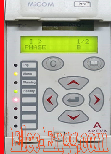
– I just need small information about this code that is showing in this Micom relay. I have already downloaded the Code list but this code is not mentioned in that. Do u have any idea what this code represents?
– U can find the error in the manual of the specific relay.
Wishing all my friends a very happy and productive new year. May 2021 erase all the bad memories we had and make the upcoming year an eventful one.

elec-engg.com
– Please provide a suggestion for this case, Line Length: 10 KM, Relay Specification: Micom P442, Relay setting: D/S- 0.300 ohms, U/P-1.2 ohm. The below problem occurs in the Pumping station, 1) Line was tripped at 8.3 KM away from UPSTREAM and 1.7 KM Away from Our pumping station.
1) Which side relay will operate?
2) what’s the recommended setting for the operation of the line?
3) which relay operates first for the above case?
The pumping station relay has seen the fault in zone 1 and as per standard operating procedure relay at pumped storage should have tripped earlier
Subjected to short circuit calculations.
3. relay at pumped storage should have operated first. The line length is too small so go with line differential. Distance relay operation is not much desired for less than 11kms line. As per the above pumping station will trip 1st and upstream will trip in zone2 if plc is there then you can trip it faster
– But in this case, Upstream was tripped. What are the reasons?
– Upstream will feed because of the fault infeed. Two relays only operate if there is a fault infeed from that particular direction
– Are you trying to say upstream tripped first?
– No, But due to some reason in the actual case upstream was tripped instead of downstream
– Ok upstream should operate for the reason already explained above
– Actually, it seems the fault is on the boundary case and if there is strong feed from upstream then there was a chance for both relays to see in zone1. As the line is short CT and PT errors too play a major issue
– Cable construction is similar to a bunch of capacitances interconnected as inter-electrode conductors. So during voltage application in the used conductor and because of the capacitance effect, a certain voltage gets to develop on the metallic sheath. Now the development of voltage depends upon the orientation/ geometry of the cable like laying, the pattern of voltage application, etc. Now to avoid this effect we should follow the following PRACTICES.
A. If the cable length is less than 1kms and the application of voltage is less than 33kv, then earth the sheath on both sides for strengthening of the earth connection.
B. If more than 1kms and less than 3 to 4 km, then earth the sheath at one side and use SVL(sheath Voltage Limiter) at the other end.
C. If the length is more than 4 kms, use cross bonding like transposition of sheath earthing at equal intervals of 1/3rd length of the total length.
NOTE: Maximum utilities use the practice of sheath EARTHING at one end and use of SVL at the other end. This usually becomes the regular practice. Other utilities do use can interact with this.

For Know the details and join groups text on WhatsApp. CLICK
Can any respected member verify the above facts as true and feasible for Hv cable earthing
– When the sheath is earthed at both ends, there will be a flow of sheath current and generation of heat. Because of it, a higher-capacity cable has to be used. This problem becomes predominant when cable lengths are more. To avoid going for higher capacity cable, sheath currents will be eliminated by keeping other ends of the sheath unearthed. To limit that another end voltage SVL is used. If you have sufficient capacity cable considering sheath currents, you can earth both ends also and it needs no SVL.
Our completed Courses:
- IEC 61850 Configurator Training (4 Hrs)
- DIGSI 4 Offline Video Training (3 Hrs)
- DIGSI 5 Offline Video Training (7 Hrs)
- ETAP VIDEO Training (5.5)
- PSCAD Video Training (4 Hrs)
- PCM 600 Video Training (4 Hrs)
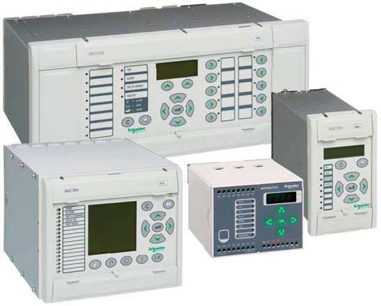
- MiCOM Relays Training Package (4 Hrs)
- Testing and Commissioning of Protective Relays