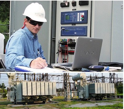
The busbar differential protection function (87BB) is the main protection function to protect busbars, and It relies on Kirchhoff’s current law. This law states that the vectorial sum of all currents flowing into a closed area must be zero.

Topics related to busbar protection and how to configure and set the busbar protection parameters have been recorded.

The various types of busbar arrangements are used in the power system. The selection of bus bars is depended on different factors for instance reliability, flexibility, cost, etc.

Single Bus-Bar Arrangement
single bus station with transfer bus (Main and Transfer Bus Arrangement)
double bus-single breaker station
double bus-single breaker station with the transfer bus
double bus-single breaker station with two bus-section and two bus-coupler breakers
one-and-a-half breaker station
double bus-double breaker station
mesh or ring bus station

More details about the Busbar protection training package: Click here

Main Training:

  • Busbar Protection training 01 (5 minApril 14, 2022)
  • Busbar Protection training 02 (6 minApril 14, 2022)
  • Busbar Protection training 03 (8 minApril 14, 2022)
  • Busbar Protection training 04 (9 minApril 19, 2022)
  • Busbar Protection training 05 (9 minApril 27, 2022)
  • Busbar Protection training 06 (8 minApril 27, 2022)
  • Busbar Protection training 07 (10 minApril 27, 2022)
  • Busbar Protection training 08 (06 minApril 27, 2022)
  • Busbar Protection training 09 (16 minMay 01, 2022)
  • Busbar Protection training 10 (19 minMay 01, 2022)

supplementary Files: To save your time, we’ve gathered critical related files/ videos and attached them to the course as additional files.

  • Busbar protection REB670 2.0 IEC Application Manual
  • Busbar protection REB670 2.0 IEC Commissioning Manual
  • Busbar protection REB670 2.0 IEC Technical Manual
  • SIPROTEC 4 7SS52 Distributed Numerical Busbar and Breaker Failure Protection (catalog)
  • SIPROTEC 4 7SS52 Distributed Numerical Busbar and Breaker Failure Protection (Manual)
  • Busbar Differential Protection, SIPROTEC 7SS60 Centralized Numerical Busbar Protection, SIPROTEC4 7SS52 Distributed Numerical Busbar, and Breaker Failure Protection, SIPROTEC 7SS50 Numerical Busbar, and Breaker Failure Protection, SIPROTEC 7VH60 High-Impedance Differential Protection Relay
  • 01 Busbar Protection Training Introduction
  • 02 Busbar Protection training Bus Configurations
  • 03 Busbar Protection training BB Components
  • 04 Busbar Protection training Low Impedance Schematic1
  • 05 Busbar Protection training Low Impedance Schematic2
  • 06 Busbar Protection training High Impedance Schematic
  • 07 Busbar Protection training Siemens 7SS52
  • 08 Busbar Protection training ABB REB500
  • 09 Busbar Protection training SINGLE Bus Without Coupler
  • 10 Busbar Protection training Double Bus Single Breaker 2 CTs
  • 11 Busbar Protection training Double Bus Single Breaker 1 CT
  • 12 Busbar Protection training CT Location Aux Contacts
  • 13 Busbar Protection training Dead Zone Load Transfer
  • 14 Busbar Protection training Breaker Failure Protection
  • 15 Busbar Protection training EndFault Definition Requirements
  • 16 Busbar Protection training EndFault DoubleBus
  • 17 Busbar Protection training EndFault 1 and Half CB
  • 18 Busbar Protection training High Impedance BBP Setting Calculation
  • 19 Busbar Protection training BBP Stability and Sensitivity Tests
  • Busbar Protection
  • All bus bar schemes in the substation-Busbar system in substation-Power system-Typical bus configuration
  • BusBar Schemes in Electrical Substation Part 1 Bus fault cases operation explained with diagram
  • Bus-Bar Schemes in Electrical Substation Part 2 Bus fault cases operation explained with diagram
  • Differential protection
  • Main and Transfer bus bar Differential Protection – Bus bar protection 7SS85 relay testing
  • Busbar Protection Fundamentals
  • High impedance busbar protection
 IED with two low-impedance differential protection zones and eight three-phase CT inputs

Any queries, please feel free to contact us: saeed61850@gmail.com

Course Title & Dates

  • Config and testing of the generator, transformer, line, and motor protection functions
  • 4 days

Trainer Profile

Registration

email: saeed61850@gmail.com

Tentative Course Schedule

Day 1
  TIME 

TRAINING SCHEDULE & TOPICS

9.00am – 10.30amABB relays, PCM 600 installation, Connectivity pack installation, Hardware configuration, Application configuration, Signal matrix Parameter setting, IED read and write IED online monitoring and signal monitoring Disturbance, and event viewer
10.30 am – 10.45 amTEA BREAK
10.45am –1.00pm  SIPROTEC 5 relay families and applications DIGSI 5 and device driver installation SIPROTEC 5 configurator Relay configuration
1.00pm – 2.00pmLUNCH
2.00pm –3.30pm    SIPROTEC 4 Relay families DIGSI 4 installation Masking I/O CFC Fault Recorder
3.30pm – 3.45pmTEA BREAK
3.45pm – 5.00pm    MiCOM relays range, naming, and application Easergy Software Configuration and PSL Event and disturbance recorder

Day 2

  TIME 

TRAINING SCHEDULE & TOPICS

9.00am – 10.30am    OMICRON CMC Test universe softwareAMT105  AMPro software signal view, impedance view, vector view different types of test modulesRIO, XRIO, and PTL
10.30 am10.45 amTEA BREAK
10.45am – 1.00pm        Principle of Differential Protection87G Generator Differential Protection87T Trans. Differential Protection87M Motor Differential Protection87L Line Differential Protection
1.00pm – 2.00pmLUNCH
 2.00pm – 3.30pm    Testing of the Differential protection function (87G, 87T, 87M, 87L) Operating CharacteristicDifferential ConfigurationDifferential trip time-harmonic
3.30pm – 3.45pmTEA BREAK
3.45pm – 5.00pm    81O Over frequency Protection81U Under frequency Protection59 Overvoltage Protection27 Under voltage ProtectionTesting of the Over/under frequency (81O/ 81U)Testing of the Over/Under voltage (59, 27)
contact us to reserve your seat

Day 3

  TIME 
TRAINING SCHEDULE & TOPICS

    9.00am – 10.30am    50/51 Overcurrent protection50N/51N earth fault protection 67/67N Directional/ directional earth fault protectionRelay coordination
10.30 am – 10.45 amTEA BREAK
    10.45am – 1.00pm        Overcurrent test moduleOvercurrent RIO block settings of the Overcurrent test module testing of the Overcurrent and Directional Overcurrent Functions (67, 67N, 50, 51, 50N, 51N)
1.00pm – 2.00pmLUNCH
2.00pm – 3.30pm    46 Negative Phase Sequence Protection51V Voltage-Dependent O/C Protection49S Stator Overload Protection49R Overload Protection48 Motor starting time supervision51L lock rotor
3.30pm – 3.45pmTEA BREAK
 3.45pm – 5.00pm    Testing of the Negative Phase Sequence ProtectionTesting of the ANSI 51V Voltage-Dependent O/C ProtectionTesting of the ANSI 49 Overload Protection


Day 4

  TIME 
TRAINING SCHEDULE & TOPICS

9.00am – 10.30am  Distance protection line simulation in PSCADTesting of the fault location function
10.30 am – 10.45 amTEA BREAK
10.45am – 1.00pm      21 Line distance protection40G Field Failure Protection21G Generator Under impedance Protection78 Pole Slipping Protection
1.00pm – 2.00pmLUNCH
 2.00pm – 3.30pm    Distance RIO block shot Test, Check Test, Search Test, Z\t Diagram, Zone SettingsTesting of the Distance function (21)Testing of the 40G Field Failure Protection
3.30pm – 3.45pmTEA BREAK
 3.45pm – 5.00pm    64S Generator, 95% &100% Stator Earth Fault Protection, 51/27 Generator, Dead Machine Protection, 24G Generator, Over flux Protection, 47G Generator, Fuse Failure Supervision, 32R Generator, Reverse Power Protection
  • Distance Protection
  • Differential Protection
  • Busbar Protection
  • Generator Protection
  • Restricted Earth Fault Relays
  • Back up Relay

Our Video Training Products:

Sample discussion in our WhatsApp group, Join Us for free discussion, (Click)

The parameter set cannot be transferred to the device.

The reason for this is that the parameter for the EN100 module has not yet been updated after changing the IEC61850 system interface. To do so, open the “update” property page of the IEC61850 station and update all parameter sets. A transfer to the device now works again.

Terms of I> mean Time delay O/C, and I>> is instantaneous O/C

problem: 1ph fault but relay give 3ph command in Siemens 7SA522

Solution: In the matrix, u can raise the signal 1ph trip permitted by AR via one BI. Normally Simense relay giving always 3ph trip

Error in Siemens low Impedance busbar protection 7SS52 and alarm on bay units

for joining telegram or WhatsApp channel & groups (Click)

Our completed Courses: