To join our protection relay WhatsApp group, please click

Join 20 WhatsApp groups for protection engineers

20 WhatsApp Groups for protection engineers

  • WhatsApp Grp 01: Protection Relay – General
  • WhatsApp Grp 02: Substation Automation – General
  • WhatsApp Grp 03: Transmission line protection
  • WhatsApp Grp 04: Transformer protection
  • WhatsApp Grp 05: Motor protection
  • WhatsApp Grp 06: Generator protection
  • WhatsApp Grp 07: Overcurrent and Earth Fault Protection
  • WhatsApp Grp 08: Busbar protection and Bay controller
  • WhatsApp Grp 09: Breaker protection and control
  • WhatsApp Grp 10: Protection Relay Testing and commissioning
  • WhatsApp Grp 11: DIgSILENT
  • WhatsApp Grp 12: ETAP
  • WhatsApp Grp 13: PSCAD
  • WhatsApp Grp 14: IEC 61850 configuration
  • WhatsApp Grp 15: Switchgear GIS & AIS
  • WhatsApp Grp 16: GE Relay Configuration
  • WhatsApp Grp 17: SIEMENS Relay configuration
  • WhatsApp Grp 18: Schnider Relay configuration
  • WhatsApp Grp 19: SEL Relay Configuration
  • WhatsApp Grp 20: ABB Relion configuration or more services,
  • send a message to our WhatsApp support team, click

Sample discussion:

– I want to know what is the main Reasons for Transformer Bushing Failures.
– Can u share the image?
– Sir Actually Site Pic Regarding any Problem does not allow to Share as per Site Policy.
So I can’t share it.
– Good afternoon, would anyone know what the default password for ZIV protection relays?
– Try with Ziv or zivercom.
– Username; zivercom Password; Ziv
– It worked.
– Anyone has substation CAD or Revit.

– I am facing Digsi 4.91 installation problem in windows8.1
– It shows that Digsi 4.91 can’t install in Windows 8.1
-Please check the system requirements for software installation.
– Check, in the manual.


If anyone is interested in ETAP discussion Whatsapp group, send ETAP to me on Whatsapp (Click)


– Which power analyzer is best for Harmonic measurement? I need to measure Harmonics order’s magnitudes and phase angle.
– Fluke 1735
– Fluke 434

Which power companies are using the whole IEC61850 (Sample Value, GOOSE, and MMS) in their substations? or are they just adept GOOSE and MMS only? The CT and PT are still conventional types?

– How to check this relay?
– the setting is 20%

Inject the current above that value and check the trip time. Pick up and all.
– How to test locked rotor in Easergy p3 g32 relay?
– How do know the TMS and type of curve of this overcurrent relay? how to Calculate the time of tripping?
…3-sec normal inverse curve.
– TMS 0.2
– Would you please explain?
– How do you get it?
-100% IDMT settings. 800% instantaneous setting.
– Check there I don’t know what to call them, those toggle switch which side they are selected just sum it, And multiply by the factors mentioned and you will get the setting.
– For the left side instant setting
200 + (2+1) 200 = 800 % For TMS 0.12= 0.2

-The upper two are for different purposes.
– Different tables are mentioned over there Just check the S 1 -8 no. And then see the upper two toggle positions.
– I hope it is clear to you.

– We have two transformers (66/11.5 kV, 50/55 MVA, 600A NGR earthed on the 11.5kV side). There is two incomer-one bus coupler scheme at 11kV bus.
– Due to some constraints, we are not able to get a 66 kV supply from the grid. However, 11kV direct supply is offered by the grid for no-load charging at an 11kV bus from the identical transformer on the grid side.
– Please revert with technical constraints related to the subject.
– Hi everyone, l hope you are well, and safe; could you share ” relay coordination and setting for substation 230/400kv(excel sheet+ explanation) thanks in advanced.

– We are facing one issue in one of the plants that we have laid 3Core 400 Sq.mm 22KV XLPE cable to provide power supply to one of the small production units. The cable length is approximately 2500Mtrs and the state electricity board has implemented KVAH billing now. So the problem is even though there are zero loads at receiving end source end meter shows 40KVAH apparent power and 40KVAR reactive power. Is it because of cable capacitance? If yes what is the solution to avoid the same?

– As KVAH billing is implemented it is directly impacting cost very heavily.

– Can experts give your valuable inputs on this.
– Since it is a cable then it will be generating ” VAR”.. hence it is not possible 40 kVAH & 40 kVAR
– there is a chance of a cable charging current. Once check with the leakage meter in the secondary side of metering MFM, check how much leakage current is showing. And also ensure whether c.t wiring is connected properly or not it means the metering core of c.t is to be connected to meter only and also protection core of c.t is always connected to be relaid. I think the only possibility is to charge current.
– We have checked the wiring and it doesn’t have any issue. Also, we have removed the cable earthing at one end which was connected to both ends earlier. But still, the problem persists.
– Check cable insulation.
– Pls share the SLD with CT location.. and also cable parameters.
– Is it a cable feeder or it is connected through a transformer at your end and of course power provider end power factor to be confirmed.
– I think it is OK, the cable is 2.5km long, 40kVAR is 1 amp at 22kV. Who can explain why it is wrong?
– Hi team, I want to know which electrical software is better to learn to come into the design side?
– If anyone from the design side or if anyone knows better share the knowledge so it will be helpful to someone who doesn’t know.

Electrical engineers can find us on WhatsApp, Likundon, Instagram, site, and email.
To follow:

Telegram
t.me/elec_engg

Instagram
instagram.com/elec_engg

Website
Elec-Engg.com
ProtectionRelay.com

Email
info@elec-engg.com

To join our protection relay WhatsApp group, please send interest on Whatsapp: +989129613659

-How to simulate protection function using a virtual injection in Vamp255
– How to assign the DR in Micom Esergy Studio soft

You can also benefit from our free files and see our training packages at the link below.
https://elec-engg.com/category/training-course/

– Can anybody pls provide R, X/Z values of 132kv & 220kv lines with Panther, Zebra ACSR conductors. Rgds
– To be used for distance relay settings.
– Anyone can suggest pole slipping protection calculation for 4.9 MW TG. There is a total of 3 incomers on the 11 kv switchboard. 2 from grid trafo and 1 from TG. In the normal operating scenarios, all 3 incomers are synchronized and BC is closed. I have doubts regarding the considering impedance of the transformer.

-Even when the differential is less than restraining current Relay operated on minimum operating current.

– Maybe it tripped on cross-phase tripping like detection in one phase trips the other two.
– Because differential always has three-phase tripping.
-Is there any formulae for calculating? I didn’t find any cross-phase calculation in the relay manual
– No sir, the formula is not there, in siemens relay, the function is there. Cross tripping function which we can enable or disable.
– Which relay is this?
– P632
– I don’t think it’s there in this relay.
– But it is the case usually, protection operation in one phase, operates the three-phase protection.
-Does anyone have a catalog or technical manual of power panel/receptacle panels/ lighting panels?
– RET? And REM

– Can anyone explain the purpose of cable sheath tests
– It can make sure the cable sheath functionality like a uniform, induced voltage, and one end grounding, etc.
– I mean that are power cables. I am not sure that your meaning is a control or power cable.
– Yes for power cables
– I’m glad to inform you that I finalized my one-year apprenticeship as a relay testing engineer trainee in KSEB Pvt Ltd in India. Now I’m looking forward to entering a new opportunity in the same field. I will be grateful if you inform any suggestions or vacancies related to the same for improving my skill and career. Don’t hesitate to contact me if you have any concerns.
– Guys wanted to know regarding the excitation current of ct.. what will happen if the excitation current is more than the given nameplate data.. for ex: knee voltage >= 500 and knee current <= 25mA in nameplate for px class. But during testing, if knee voltage is more than 800V and knees current 32mA. so what will be the effect on protection in this case?

– I need to change the IP address through the screen of relay 7SJ80 but not accepted relay so how will change only by screen
MAIN MENU > Settings > Setup/Extras > IP-Config > PC port > IP-Address

– Can any Share 220 kV GIS building layout??
– Does anyone has a test report of the p111 relay.
– What is the reason for this?
– I think installation problem once reinstall the software PCM600
– Thank you will come back to you tomorrow
– Can we check coordination between generator 51V and outgoing Transformer feeder 51?
– Yes for phase faults

If anyone is interested in the IEC61850 discussion Whatsapp group, send ETAP to me on Whatsapp

Hello, thank you for visiting our site
By joining our WhatsApp and Telegram groups, talk to the world’s electrical engineers and solve your problems about electricity. You can also benefit from our free files and see our training packages at the link below.
https://elec-engg.com/category/training-course/

– Why this ramping button is inactive?
– Because of size value is zero.
– Ramp it by 0.01A or 0.001A whatever your requirement is.
– Got it to thank you
– Can someone explain the Total Owning cost of the Transformer?
– If you have Can send ABB Ekip training slides?

– Can anyone tell me how to rectify this issue installation problem?
– Need to know one info Freja 300 relay testing kit
– Is it a very good kit or Omicron kit is good lne For CT? 1st core used for main protection 2nd core used for backup protection. 3rd core use for metering purpose Then what is the purpose of the 4th core?
– There may be 6 cores too, for different purposes, like main1, main2, bus bar1, busbar2, metering, spare.
Depends upon the requirement and scheme of the system.
– Yes It’s True.

– Could you please help me with how to configure in ABB RED670 front panel push bottom configuration to activate one binary output?
– Pcm 600??
-Yes
– please share the screenshots I am waiting
– Go to HW configuration?
– 7sd610 is not communicating to pc when I tried thru the device to DIGSI plug and play
– How to clear this error?
– Do power recycling
– And check supervision relay elements after that upload Pspx file again

– Anyone has an idea how to connect SEL351A with SEL651R?
– How to block power sing in a distance relay? Simply, disable power swing in settings
– Blocking & disable are two different thing
– Which relay do you have sir
– SEL

– One HV motor has two feeders for redundancy. we want seamless changeover from one feeder to another in case of mechanical failure. Is it possible for a higher rating HV motor? How?

– What kind of problem and how do you expect mechanical problems in the feeder when it is running
– Basically, the client wants to prevent an outage of power by this. Is it possible in the HV system?
– Online
– Don’t Think mechanical failure expected
– Nice to meet you too, I am Peter
For RTU needs 4 cards: 1. digital input, 2. digital output, 3. analog input 4. analog output
– Bay control unit for SAS system
– Can we say it is like PLC, But with higher availability, redundancy, robust voltage, and disturbance handling, With different comm protocols and Network redundancy.
– Yes
– does it follow any standards like PLC has IEC61131?
– IEC 601850 – 101 & 104
– This is for communication and data sharing. What about logic programming?
– WHAT IS THE WORK OF THE FOTE PANEL?
– IEC 601850
– What should be done if VCB doesn’t pass contact resistance criteria? VCB should be used or not?
– What should be done if VCB doesn’t pass closing time criteria?
VCB should be used or not?
– Fiber optic terminal equipment. This is for line communication like PLCC
– No. must repair/service before put into the system
– Yes digital power line carrier
– What about hipot test?
– hipot is passed, CB is old.
– If both contact resistance and timing test fail then it is recommended to go for replacement even hipot passed.
– Finally, check if any mechanical problem can be rectified.
– Is this a vacuum contactor or vacuum circuit breaker?
– Also, compare all 3 phases of contact resistance and timing. And all these tests can be compared with the last test results, FAT.
-How old is this?
– What manual says about a lifetime? With this, you can decide whether it is premature failure due to quality or any inbuilt issues, or lack of maintenance
– What is the distance between ZONE 1, ZONE 2, ZONE 3?
– In distance protection or busbar protection?
– Distance protection
-What is the means of this relay?
– Carrier aided trip or communication aided trip, As per RK commission, Z1 is 80 percent of PL, Z2 is 150 percent of PL and Z3 is 120 percent of PL and Longest line.
– On which mode u have set the line DTT, DUTT, PUTT, or POTT
– It means that this relay is tripped based on the signal received from the far end relay.

– “How to configure RCBs and Data sets in ABB RED670 relays by referring to existing CID files?
– If any kind of procedure/guidelines, please share them with me

– You must be able to upload the CID file into the IEC61850 tool and it’ll help you to configure the IED
– Still, I am not clear. Can you elaborate on it?
– Use the PCM600 configuration tool from abb to upload the CID file into IED. Download and install PCM600 from the ABB website
– I have PCM600 V2.8 software
– I have an existing PCMP project file that doesn’t have datasets and RCBs. But I have commissioned the CID file back up. Now I want to create new data set and RCBs in the PCMP Project file with help of commissioned CID file. Pls, note I am doing it for V1.1 relays. So pls check and advise me
– Do we need to go for a higher CT ratio If CT secondary is not suitable for peak fault?
Please share your opinion
– Yes. Greater Knee point voltage CT to be chosen
– you can connect two secondaries of the same CT in a series. You can use a secondary reserve, both secondaries must be equals (ratio, class,….)

– This connection is similar to installing a higher knee point CT
– I have 1s1-1s2 and 2s1-2s2. How to connect both ct sec in series? Moreover these 2 secondary connections 2 different relays. In such a case how it should be connected?
– I am facing a problem that after under-voltage takes place, the breaker is tripped, and after reset and normalization of voltage, I can’t able to ON the breaker. So after turning off /on the breaker control supply then I can able to turn on the breaker.

Electrical engineers can find us on WhatsApp, Likundon, Instagram, site, and email.
To follow
And use our WhatsApp groups and easily talk to engineers around the world.
plz text on Whatsapp: https://elec-engg.com/whatsapp-group-for-protection-engineers/

Telegram:
t.me/elec_engg

Instagram
instagram.com/elec_engg

Websites:
Elec-Engg.com
ProtectionRelay.com

Email:
info@elec-engg.com

– How to make the Rio file for the ABB (rel670) relay be tested in the distance feature of the omicron 3-ph testing kit?
– Open parameters settings, go to file, export, save as Rio
– Option is export parameters in xrio format?
-Export in xrio
– Load PTL file of RED670 in omicron software, Then import this xrio file But when that was imported in ptl file, only z1 p-e is coming
– Check graphs of all enabled zones are showing or not
– Graphs are showing but when a fault is given, no response
– Relay is sensing fault or not?
– Mean operating or not?
– Not sensing fault
– Not operating
– I think the problem in ptl file, is it is different for different version relays?
– Download the latest file from the PTL library
– Will it works in the distance module or in the advanced distance?
– Advance
– But what is the way to test with the distance module as I have only one distance module in my kit
– Anybody has ptl file for P545?
– It can be downloaded from the OMICRON website
– Third-party can download?
– Yes. you have to sign up and register
– Ok let me check
– Can anyone tell me what is the issue?
– Anybody from ABB LV?
– Can you send EKIP Connect the latest software manual? Or training slides
– Can anyone help me to find out transformer vector group Dy11d0d (-15)d(+15)

– Anyone has procedure test sheets for test commissioning protection relays
– Any opening for the oil and gas sector?
– Anybody has FCMA soft starting settings

– This is DC supervision relay, often this relay gets the problem, In my out of 11, 4 were not working. Although Input DC was correct.
– Please teel why it is getting problem?
– How do we have to troubleshoot my site?
– There is some short between two terminals… is that done( I think it I some status)
– Terminals for 220 and 110v dc are different.
– I think you would have connected 220 v dc to 110vvdc terminal
– I have checked 110 VDC from dcdb panel
– Check the relay on Which terminal has connected the supply?

– How to see ethernet NTP IP address in 7sa522 relays?
– Does anybody know the basic working difference of REF in autotransformer besides from REF in conventional transformer?
– Binary input/output card.

– How the mccb is protecting against cable heating issues due to undersize?
– Can anyone tell me how many NO & NC contacts are available for this model number? Alstom UV relay.
– Got it guys after seeing the sticker on the box. Thank you

– We lost the password for this how we can reset to default value please help Masibus 2330
– In the substation present, the DC source is 110 v, and the circuit breaker set at 220 v will the breaker operate or not.
Kindly help me.
– some substations have two supply 110v & 220v
– there is only one source 110v
The C.B isn’t working.
– Till now we have not charged the bay
– It’s under construction
– DO YOU TRY TO TEST BY 220V?
– 220v source is not available
– Could you replace the coil?
– manufacturers make different types of coils. For example, 48, 110, 125 and 220V
– Reactive power calculated formula?

– PSS FULL NAME?
– Power System Stabilizer

Electrical engineers can find us on WhatsApp, Likundon, Instagram, site, and email.
To follow
And use our WhatsApp groups and easily talk to engineers around the world.
plz text on Whatsapp:
https://elec-engg.com/whatsapp-group-for-protection-engineers/
Electrical engineer Dr. Saeed Roostaee with his online training on using and working with relays will help you to work with relays in the shortest possible time and at a reasonable price.
Follow us on

Whatsapp: +989129613659

Telegram:
t.me/elec_engg

Instagram:
instagram.com/elec_engg

Websites:
www.Elec-Engg.com
www.ProtectionRelay.com

Email:
info@elec-engg.com

– Anybody have an overflux curve of 500 MVA ICT of BHEL make?
– How to find excitation voltage in a brushless synchronous motor?
– please let me know if somebody has the loss figures for 100 MVA transformer 132/33kV. How to remove this error?
-What is the purpose of these dual delta primary windings in VFD configuration?
– Harmonic mitigation if phase shifting at secondary
– Ok. But why dual delta. Harmonic mitigation is possible with a single delta also
– Anybody has a download link for SEL ACSELERATOR QuickSet SEL-5030 Software, please?
– Can download it from the SEL website it’s free
– I have applied for an account, but it has not yet been authorized

– What is the password to change the settings
– 0002
– How to calculate the line losses in an ac transmission line? And how to disable directional overcurrent and earth fault settings at this relay
– Please share the DR standardization process of SIEMENS 7SA522 along with CFC.
– Anyone has REL 650 base connectivity package?

– 1I need the ERL LPRO4500 relay setting calculation sheet, if anyone has, pls send it.
– How to calculate REF fault current for transformer
-I injected the same current in all phases but it tripped in earth fault
-Why does this happen I checked the wiring it’s fine
– You check the star point of internal CT
– Injected directly at relay backside
– Check the phase angles
– It must be 0, 240 and 120
– Apply three current with the same magnitude and zero phase angle and check N current
– For earth, fault inject individual phase with phase angle 0 degrees. The phase angle is ok
– Which relay is this..?? Line protection..??
– simple over Current and earth fault only
– Can u share a pic of the relay showing phase angles while injecting a 3phase balanced current?
– Relay CT terminal neutral loop wrong
– Got corrected it was a mistake in setting
– How to calculate CT size for motor hp please suggest me
– Sizing of CT should include 120% of FLA and peak fault saturation and sub transient for dynamic half cycle


-Anyone in the group has an idea about microgrid relaying protection?
– Do anyone knows about Schnider ltmr relay custom logic preparation?
-No you can’t connect. Because the Current will flow on a low resistance path only. If you used 0-500 tap for R1. The same core you can’t connect R2.
– You can connect two relays in serious on a single adequate tap and configure accordingly. But don’t connect two relays in parallel, as boopathi said, the current will flow on a low resistance path. If it’s a high impedance differential protection, then don’t share the CT.
– And relay may malfunction due to the current magnitude flow into 2 different relays and the direction of the current subject type of protection.
– Can’t we use the same tap for overcurrent and then in series for high impedance REF? Not on different taps but on different cores
-In the REF phase and Neutral CTs are connected in such a way that current is nullified. So it is not possible to use over current with REF.
– In a High impedance circuit, stabilizing resistor and metrosil will be part of the ct circuit, so it’s not advisable to combine both in the same ct core
– Actually, we have commissioned many projects like this. The only thing we extended inputs to overcurrent element first then conjugated with neutral ct adding metrosil and stabilization resistance and fed to REF element.
– Technically we don’t find any issue. Maybe you have any practical experience, please share for taking care. Phase ct and neutral ct should be paralleled in such a way that the current is nullified during normal conditions. Further, how the OC relay will get the correct measurement with a high impedance circuit? Please check your secondary circuits
– High impedance coil input to relay is dedicated and it is voltage-operated although we give current as an input. However, OC elements core must be different than high Z core.
-Are you using RET 670 relay?
– Technically not correct. It may work but note that REF opération depand on CT magnétisation characteristics. It can malfunction also. REF should not operate for external faults. This is RET 670 relay CT connection for REF and over current used

Electrical engineers can find us on WhatsApp, Likundon, Instagram, site, and email.
To follow
And use our WhatsApp groups and easily talk to engineers around the world.
plz text on Whatsapp:
https://elec-engg.com/whatsapp-group-for-protection-engineers/

– I support everyone’s input if the overcurrent element is not in the relay and phase CT star point is not made thru the relay and parallel with neutral ct.
– It all depends on the relay features and how you are making start point phase CTs.
Thanks for all your inputs.
– Hi do anyone have abb ret 543 relay communication software
– What should be the value of coil current taken by a trip coil of the breaker?
– 400 kV GE make Breaker
– Nonmagnetic cable gland is required in single-core DC cables?

– I am facing a problem with the abb rel670 relay. When the line is charged condition with both main and tie breakers in close position. If we open the main breaker, abb rel 670 is sending DT on another end. But we check the DT send logic, it is ok we checked it by taking a shutdown.
– What will be the problem?
– This is the normal logic for DT. DT is for Over Voltage, Manual Open, LBB, and Busbar trip.
– On manual-open main CB, DT will send only if tie CB is already open
– Ok. Tie CB status is given to this relay? But here the problem is when is in charged condition with both main & tie CB in the closed condition when we open the main CB only DT is sending
– Normally REL670 will not mal operate. I think there may be an issue with the logic.
– You check online signal monitoring and find out which outputs are energized during that time

– main incomer breaker of capacitor bank get trips by using relay when the power factor exceeds 0.86. The capacitor banks are newly installed. What May the reason for capacitor banks to draw more current
– Did u check each capacitor’s bank-wise currents?
– Check the load settings of the breaker.
– We are using Tapcon 320 expert in one of our sites, in which we are trying to communicate the Tapcon using the ethernet port. During which link/activity light is not glowing in ethernet port. Tapcon is showing error event 38. No connection to the communication interface card. Communication info is showing as blank; no version available in the Tapcon

Our completed Courses:

In this package, all the training courses (DIGSI 4, DIGSI 5, ETAP, DIGSI 4, DIGSI 5, ETAP, PSCAD, IEC 61850, PCM 600, Micom, and Testing Commissioning, Generator Protection, DigSilent, Busbar protection) are gathered. So You can save your money by taking all courses in one pack. Our courses aren’t time-limited and you have access to them at any time. The training link and activation number will be sent to your email immediately after payment.

The details and Demos of each course are placed below and if you need further information, please feel free to contact us.

Product Detail:

PSCAD Demo

IEC 61850 Demo & items

ETAP Demo & items

ABB PCM 600 Demo & items

DIGSI 4 Demo & items

DIGSI 5 Demo & items

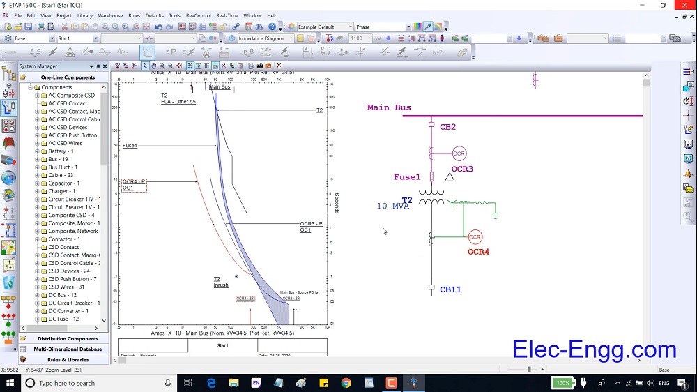
These days can’t perform many of the required analyzes in electrical networks without using the relevant engineering software. Therefore, engineering software has been very effective in industrial environments. One of the most famous software is ETAP which is used in the analysis of distribution networks in industrial Plants and is made by the Operational Technology company. In this training package, in addition to collecting the required technical information in an attractive multimedia environment, various analyzes, and how to do them using ETAP software are presented practically.

ETAP has been designed and developed for engineers to study different aspects of power systems in one integrated package.

This course is structured into 4 chapters, with theory and practical examples. It is designed for protection engineers to understand the power system, short circuit concept, protection, and coordination.

Chapter 1, part 01: overviews different tools in ETAP with an example. ETAP offers a suite of fully integrated electrical engineering software solutions including load flow, short circuit, protection and coordination, harmonic analysis, transient stability, cable ampacity, arc flash, optimal power flow, and more. Some of these tools may not be required in our study. So we should know which part is the most important tool for us. This part overviews different parts of ETAP before starting the course. In this way, we can find the main tools and parts on which we should focus on.

Chapter 1, part 02: An introduction to ETAP software. We start with creating a new project and explaining different toolbars and menus in ETAP.

Chapter 1, part 03: This part overviews the main parameters of a busbar, 2 winding transformers, and 3 winding transformers.

Chapter 1, part 04: Overview of the main parameters of a transmission line and cable.

Chapter 1, part 05: overviews the main parameters of a static load, lumped load, and power grind.

Chapter 2, Part 01: shows how to study parameters with load flow analysis. To do so, we run a load flow analysis on a simple one-line diagram and study the effect of different parameters.

Chapter 2, Part 02: overviews the load flow study case and plot option settings.

Chapter 2, Part 03: presents a practice to understand the parameters of load, equipment cable, busbar, cable, and transformer deeply. Then it presents load flow and load analyzer tools.

Chapter 2, part 04: overviews the main parameters of low voltage circuit breaker and high voltage circuit breaker.

Chapter 2, part 05: overviews the main parameters of an induction machine and how to model an induction machine in three different methods.

Chapter 2, part 06: overviews the main parameters of a synchronous generator.

Chapter 2, Part 07: presents a practice to understand the parameters of an induction machine and a synchronous generator deeply.

Chapter 2, Part 08: presents how to remove the critical alarm. To do so CB overload, cable overload, and transformer overload alerts have been removed. To remove these alerts, we should know how to do cable sizing and transformer sizing in ETAP.

Chapter 3, Part 01: shows the effect of different parameters in the short circuit current. An induction motor can inject current to a grid even more than an equivalent generator, this part show this concept in ETAP.

Chapter 3, Part 02: explains the settings in the short circuit analysis. To explain the parameters of short circuit analysis and understand the short circuit modeling in ETAP, we have simulated an AG fault in PSCAD.

Chapter 3, Part 03: presents several duties and tools in short circuit analysis mode.

Chapter 4, Part 01: overviews the elements which are related to relay protection and coordination.

Chapter 4, Part 02: shows overcurrent parameters in ETAP and relay configurations software. The setting of overcurrent relays (P121 and distance relay SEL 421) are shown in the configuration software (Esergy studio and AcSELerator quick set software).

Chapter 4, Part 03: In this part, three-phase voltage and currents are injected into the SEL 421 with a secondary test kit (Omicron CMC 256) to explain the values in a relay and test the intravenous overcurrent function.

Chapter 4, Part 04: presents how to calculate the CT ratio and time delay overcurrent elements (Ansi 51). Then the coordination between two relays is explained with the help of start view tools.

Chapter 4, Part 05: the coordination between three relays and how to test the coordination with the help of the sequence viewer tool are presented.

Chapter 4, Part 06: This part explains the plot option parameters in the Star View.

Chapter 4, Part 07: This part explains how to set instantaneous overcurrent parameters (ANSI 50).

Chapter 4, Part 08: presents how to calculate overture ground elements in ETAP and how to set these parameters in the relay.

Chapter 4, Part 09: This part presents how to add a proper fuse to a feeder and coordinate the relays with the fuse.

Chapter 4, Part 10: This part explains the protection page of the main elements and how to protect an element with an overcurrent element.

Chapter 4, Part 11: This part presents helpful tools in the protection and coordination study room.

WhatsApp: +989129613659

Email: info@elec-engg.com

ETAP Training pack

  • Language: English
  • Length: 5.5 hours online pre-recorded video
  • Full lifetime access
  • Free technical support
  • Auxiliary files
  • Certificate of completion
  • Trainer: Dr. Saeed Roostaee (Profile)

This image has an empty alt attribute; its file name is 4.png

Latest updates:

  • Updated on 4th July 2020: Chapter 2 Part 9 – Load Flow practice (ETAP project file+Video)/ Free update
  • Updated on 11th July 2020: Protection and coordination practice (ETAP project file)/ Free update
  • Updated on 19th July 2020: ETAP training WhatsApp group
  • updated on 21 Feb 2022: Short Circuit Analysis based on the IEC 60909 Standard (pdf file)
  • update 27 Aug 2022: Load Flow, Short Circuit, Transient Stability, Optimum Capacitor Placement, and solar PV system (Video)

Download ETAP Training Package

ETAP has been designed and developed for engineers to study different aspects of power systems in one integrated package. This course is structured into 4 chapters, with theory and practical examples. It is designed for protection engineers to understand the power system, short circuit concept, protection, and coordination.

Chapter 1, part 01: overviews different tools in ETAP with an example. ETAP offers a suite of fully integrated electrical engineering software solutions including load flow, short circuit, protection and coordination, harmonic analysis, transient stability, cable ampacity, arc flash, optimal power flow, and more. Some of these tools may not be required in our study. So we should know which part is the most important tool for us. This part overviews different parts of ETAP before starting the course. In this way, we can find the main tools and parts on which we should focus on.

Chapter 1, part 02: An introduction to ETAP software. We start with creating a new project and explaining different toolbars and menus in ETAP.

Chapter 1, part 03: This part overviews the main parameters of a busbar, 2 winding transformers, and 3 winding transformers.

Chapter 1, part 04: Overview of the main parameters of a transmission line and cable.

Chapter 1, part 05: overviews the main parameters of a static load, lumped load, and power grind.

Chapter 2, Part 01: shows how to study parameters with load flow analysis. To do so, we run a load flow analysis on a simple one-line diagram and study the effect of different parameters.

Chapter 2, Part 02: overviews the load flow study case and plot option settings.

Chapter 2, Part 03: presents a practice to understand the parameters of load, equipment cable, busbar, cable, and transformer deeply. Then it presents load flow and load analyzer tools.

Chapter 2, part 04: overviews the main parameters of low voltage circuit breaker and high voltage circuit breaker.

Chapter 2, part 05: overviews the main parameters of an induction machine and how to model an induction machine in three different methods.

Chapter 2, part 06: overviews the main parameters of a synchronous generator.

Chapter 2, Part 07: presents a practice to understand the parameters of an induction machine and a synchronous generator deeply.

Chapter 2, Part 08: presents how to remove the critical alarm. To do so CB overload, cable overload, and transformer overload alerts have been removed. To remove these alerts, we should know how to do cable sizing and transformer sizing in ETAP.

Chapter 3, Part 01: shows the effect of different parameters in the short circuit current. An induction motor can inject current to a grid even more than an equivalent generator, this part show this concept in ETAP.

Chapter 3, Part 02: explains the settings in the short circuit analysis. To explain the parameters of short circuit analysis and understand the short circuit modeling in ETAP, we have simulated an AG fault in PSCAD.

Chapter 3, Part 03: presents several duties and tools in short circuit analysis mode.

Chapter 4, Part 01: overviews the elements which are related to relay protection and coordination.

Chapter 4, Part 02: shows overcurrent parameters in ETAP and relay configurations software. The setting of overcurrent relays (P121 and distance relay SEL 421) are shown in the configuration software (Esergy studio and AcSELerator quick set software).

Chapter 4, Part 03: In this part, three-phase voltage and currents are injected into the SEL 421 with a secondary test kit (Omicron CMC 256) to explain the values in a relay and test the intravenous overcurrent function.

Chapter 4, Part 04: presents how to calculate the CT ratio and time delay overcurrent elements (Ansi 51). Then the coordination between two relays is explained with the help of start view tools.

Chapter 4, Part 05: the coordination between three relays and how to test the coordination with the help of the sequence viewer tool are presented.

Chapter 4, Part 06: This part explains the plot option parameters in the Star View.

Chapter 4, Part 07: This part explains how to set instantaneous overcurrent parameters (ANSI 50).

Chapter 4, Part 08: presents how to calculate overture ground elements in ETAP and how to set these parameters in the relay.

Chapter 4, Part 09: This part presents how to add a proper fuse to a feeder and coordinate the relays with the fuse.

Chapter 4, Part 10: This part explains the protection page of the main elements and how to protect an element with an overcurrent element.

Chapter 4, Part 11: This part presents helpful tools in the protection and coordination study room.

Protection and Coordination Practice

ETAP is an analysis platform for designing, simulating, operating, and automating generation, distribution, and industrial power systems. In this course, you will get entirely acquainted with ETAP software visually, and step-by-step. The material of this course is designed to help you to be more professional in this field.       

Our learners’ Certificates

  1. E 1000: Click here to download
  2. E 1001: Click here to download
  3. E 1002: Click here to download
  4. E 1003: Click here to download
  5. E 1004: Click here to download
  6. E 1005: Click here to download
  7. E 1006: Click here to download
  8. E 1007: Click here to download
  9. E 1008: Click here to download
  10. E 1009: Click here to download
  11. E 1010: Click here to download
  12. E 1011: Click here to download
  13. E 1012: Click here to download
  14. E 1013: Click here to download
  15. E 1014: Click here to download
  16. E 1015: Click here to download
  17. E 1016: Click here to download
  18. E 1017: Click here to download
  19. E 1018: Click here to download
  20. E 1019: Click here to download
  21. E 1020: Click here to download
  22. E 1021: Click here to download
  23. E 1022: Click here to download
  24. E 1023: Click here to download
  25. E 1024: Click here to download
  26. E 1025: Click here to download
  27. E 1026: Click here to download
  28. E 1027: Click here to download
  29. E 1028: Click here to download
  30. E 1029: Click here to download
  31. E 1030: Click here to download
  32. E 1031: Click here to download
  33. E 1032: Click here to download
  34. E 1033: Click here to download
  35. E 1034: Click here to download
  36. E 1035: Click here to download
  37. E 1036: Click here to download
  38. E 1037: Click here to download
  39. E 1038: Click here to download
  40. E 1039: Click here to download
  41. E 1040: Click here to download
  42. E 1041: Click here to download
  43. E 1042: Click here to download
  44. E 1043: Click here to download
  45. E 1044: Click here to download
  46. E 1045: Click here to download
  47. E 1046: Click here to download
  48. E-1047: Click here to download
  49. E-1048: Click here to download
  50. E-1049: Click here to download
  51. E-1050: Click here to download
  52. E-1051: Click here to download
  53. E-1052: Click here to download
  54. E-1053: Click here to download
  55. E-1054: Click here to download
  56. E-1055: Click here to download
  57. E-1056: Click here to download
  58. E-1057: Click here to download
  59. E-1058: Click here to download
  60. E-1059: Click here to download
  61. E-1060: Click here to download
  62. E-1061: Click here to download
  63. E-1062: Click here to download
  64. E-1063: Click here to download
  65. E-1064: Click here to download
  66. E-1065: Click here to download
  67. E-1066: Click here to download
  68. E-1067: Click here to download
  69. E-1068: Click here to download
  70. E-1069: Click here to download
  71. E-1070: Click here to download
  72. E-1071: Click here to download
  73. E-1072: Click here to download
  74. E-1073: Click here to download
  75. E-1074: Click here to download
  76. E-1075: Click here to download
  77. E-1076: Click here to download
  78. E-1077: Click here to download
  79. E-1078: Click here to download
  80. E-1079: Click here to download
  81. E-1080: Click here to download
  82. E-1081: Click here to download
  83. E-1082: Click here to download
  84. E-1083: Click here to download
  85. E-1084: Click here to download
  86. E-1084: Click here to download
  87. E-1085: Click here to download
  88. E-1086: Click here to download
  89. E-1087: Click here to download