Information

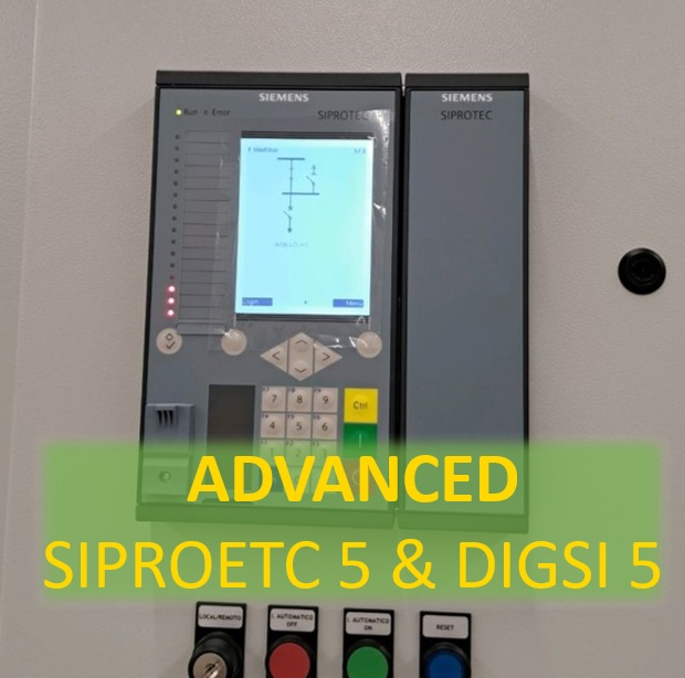
  • Course Name: SIPROTEC 5 and DIGSI 5 (advanced)
  • Trainer: Dr. Saeed Roostaee
  • Format: Pre-recorded videos (demo is available)
  • Course creation: June 2023
  • Last update: July 2023

Note: This course can also be held either Online or Face to face based on the request

Course Structure:

  • Module 1: SIPROTEC 5 Hardware and ordering
  • Module 2: Starting with DIGSI 5
  • Module 3: Working with SIPROTEC 5 in online mode
  • Module 4: System Functions
  • Module 5: Function Groups
  • Module 6: SIPROTEC 7SJ8
  • Module 7: SIPROTEC 7SA8
  • Module 8: SIPROTEC 7UT8
  • Module 9: SIPROTEC 7SS8
  • Module 10: SIPROTEC 7SK8
  • Module 11: SIPROTEC 7VK8
  • Module 12: SIPROTEC 7SD8
  • Module 13: SIPROTEC 7SL8
  • Module 14: SIPROTEC 7SX8
  • Module 15: SIPROTEC 7UM8
  • Module 16: SIPROTEC 7MD8
  • Module 17: Functions and Settings
  • Module 18: Signals and Masking IO
  • Module 19: CFC
  • Module 20: Control Functions
  • Module 21: Display Page configuration
  • Module 22: Functional Tests
  • Module 23: Measured Values
  • Module 24: Power Quality
  • Module 25: Supervision
  • Module 26: Communication
  • Module 27: IEC 61850
  • Module 28: Digital Twin
  • Module 29: Case Study 7UT8
  • Module 30: Case Study 7VK8
  • Module 31: Case Study 7SA8
  • Module 32: Case Study 7SS8

Course Details (Note: This part is continuously updating)

Module: SIPROTEC 5 Hardware and order

  • SIPROTEC5 Hardware
  • DIGSI 5 installation and DDD
  • General Settings
  • DIGSI 5 User interface
  • New project + Add device (Offline)
  • Modify the order code in the SIPROTEC online configurator
  • SIPROTEC 5 Online Configurator
  • Function Point
  • SIP 5 Configuration Procedure

Module: Online & Working with SIPROTEC 5

  • Connect to SIPROTEC 5
  • Indications
  • Fault Recording
  • Log
  • Reading Indications on the On-Site Operation Panel
  • Reading Indications from the PC with DIGSI 5
  • Displaying Indications
  • Operational Log
  • Fault Log
  • Switching-Device Log
  • Ground-Fault Log
  • Setting-History Log
  • User Log
  • Security Log
  • Device-Diagnosis Log
  • Communication Log
  • Communication-Supervision Log
  • Motor-Starting Log
  • Saving and Deleting the Logs
  • Spontaneous Indication Display in DIGSI 5
  • Spontaneous Fault Display on the On-Site Operation Panel
  • Stored Indications in the SIPROTEC 5 Device
  • Resetting Stored Indications of the Function Group
  • Test Mode and Influence of Indications on Substation Automation Technology
  • Changing the Transformation Ratios of the Transformer on the Device

Module: System Functions

  • Sampling-Frequency Tracking and Frequency Tracking Groups
  • Text Structure and Reference Number for Settings and Indications
  • Processing Quality Attributes
  • Protection Communication
  • Date and Time Synchronization
  • User-Defined Objects
  • Device Settings
  • Data Types
  • Function Control
  • Connection Examples
  • Chatter blocking
  • Settings-Group Switching

Module: Function Groups

  • Voltage current 3-Phase
  • Circuit-breaker
  • Process Monitor
  • Voltage-current 1-phase
  • Motor
  • Line
  • Voltage 3-Phase
  • Analog Units
  • User-Defined Function Group
  • Recording
  • Motor Monitor
  • Current-Flow Criterion
  • Circuit-Breaker Condition for the Motor
  • Closure Detection
  • Motor-State Detection
  • Cold-Load Pickup Detection
  • Thermal Replica Rotor
  • Capacitor Bank

Module: Functions and Settings

  • Power-System Data
  • Overcurrent Protection, Phases
  • Overcurrent Protection, Ground
  • Line Differential Protection
  • Stub Differential Protection
  • Restricted Ground-Fault Protection
  • Distance Protection with Reactance Method (RMD)
  • Distance Protection with Classic Method
  • Impedance Protection
  • Power-Swing Blocking
  • Teleprotection with Distance Protection
  • Universal Teleprotection with Distance Protection
  • Ground-Fault Protection for High-Resistance Ground Faults in Grounded Systems
  • Teleprotection with Ground-Fault Protection
  • Universal Teleprotection with Ground-Fault Protection
  • Echo and Tripping in the Event of Weak Infeed 874
  • Tripping with Missing or Weak Infeed According to French Specification
  • External Trip Initiation
  • Automatic Reclosing Function
  • Directional Overcurrent Protection, Phases
  • Positive-Sequence Overcurrent Protection
  • Instantaneous High-Current Tripping
  • Group Indications of Overcurrent Protection Functions
  • Overcurrent Protection, 1-Phase
  • Voltage-Dependent Overcurrent Protection, Phases
  • Sensitive Ground-Fault Detection
  • Non-Directional Intermittent Ground-Fault Protection
  • Directional Intermittent Ground-Fault Protection
  • Negative-Sequence Protection
  • Directional Negative-Sequence Protection with Current-Independent Time Delay
  • Undercurrent Protection
  • Overvoltage Protection with 3-Phase Voltage
  • Overvoltage Protection with Positive-Sequence Voltage
  • Overvoltage Protection with Negative-Sequence Voltage
  • Overvoltage Protection with Positive-Sequence Voltage and Compounding
  • Overvoltage Protection with Zero-Sequence Voltage/Residual Voltage
  • Overvoltage Protection with Any Voltage
  • Undervoltage Protection with 3-Phase Voltage
  • Undervoltage Protection with Positive-Sequence Voltage
  • Undervoltage Protection with Any Voltage
  • Rate-of-Voltage-Change Protection
  • Undervoltage-Controlled Reactive-Power Protection
  • Voltage-Comparison Supervision
  • Fault Locator
  • Fault Locator Plus
  • Over frequency Protection
  • Under frequency Protection
  • Rate of Frequency Change Protection
  • Under frequency Load Shedding
  • Phase-Sequence Switchover
  • Instantaneous Tripping at Switch onto Fault
  • Thermal Overload Protection, 3-Phase – Advanced
  • Thermal Overload Protection, 1-Phase
  • Temperature Supervision
  • Circuit-Breaker Failure Protection
  • Circuit-Breaker Restrike Protection
  • Out-of-Step Protection
  • Inrush-Current and 2nd Harmonic Detection
  • Power Protection (P, Q), 3-Phase
  • Current-Jump Detection
  • Voltage-Jump Detection
  • Vector-Jump Protection
  • Arc Protection
  • Voltage Measuring-Point Selection

Module: Specific Functions

  • Current-Unbalance Protection for Capacitors, 1-Phase
  • Peak Overvoltage Protection for Capacitors
  • Motor-Starting Time Supervision
  • Motor Restart Inhibit
  • Load-Jam Protection Motor
  • Thermal Overload Protection, Rotor

Module: Control Functions

  • Introduction
  • Switching Devices
  • Switching Sequences
  • Control Functionality
  • Synchronization Function
  • User-Defined Function Block [Control]
  • CFC-Chart Settings
  • Tap Changers
  • Voltage Controller
  • Point-on-Wave Switch

Module: Functional Tests

  • Direction Test of the Phase Quantities
  • Functional Test Protection Communication
  • Functional Test of the Line Differential Protection
  • Functional Test for Overvoltage Protection with Zero-Sequence Voltage/Displacement Voltage
  • Primary and Secondary Tests of the Circuit-Breaker Failure Protection
  • Circuit-Breaker Test
  • Out-of-Step Protection Function Test
  • Functional Test of the Inrush-Current Detection
  • Functional Test of the Trip-Circuit Supervision
  • Power-Swing Blocking Functional Test
  • Functional Test for the Phase-Rotation Reversal
  • Functional Test for Overvoltage Protection with Zero-Sequence Voltage/Residual Voltage
  • Directional Testing for Isolated or Resonant-Grounded Systems
  • Primary and Secondary Testing of the Synchronization Function
  • Commissioning Hints for Voltage Control

Module: Measured Values

  • Operational Measured Values
  • Fundamental and Symmetrical Components
  • THD and Harmonics
  • Minimum/Maximum Values
  • Average Values
  • Energy Values
  • Circuit-Breaker Monitoring
  • Statistical Values of the Primary System

Module: Power Quality

  • Voltage Variation
  • Voltage Unbalance
  • THD and Harmonics
  • Total Demand Distortion

Module: Supervision

  • Resource-Consumption Supervision
  • Supervision of the Secondary System
  • Supervision of the Device Hardware
  • Supervision of Device Firmware
  • Supervision of Hardware Configuration
  • Supervision of Communication Connections
  • Error Responses and Corrective Measures
  • Group Indications

Module: IEC 61850

  • External Signals
  • Quality Processing/Affected by the User for Received GOOSE Values
  • Quality Processing/Affected by the User in CFC Charts
  • Quality Processing/Affected by the User in Internal Device Functions

More info and update about this course: Contac us

To participate in this face-to-face / online training course: contact us

Course Title & Dates

  • Config and testing of the generator, transformer, line, and motor protection functions
  • 4 days

Trainer Profile

Registration

email: saeed61850@gmail.com

Tentative Course Schedule

Day 1
  TIME 

TRAINING SCHEDULE & TOPICS

9.00am – 10.30amABB relays, PCM 600 installation, Connectivity pack installation, Hardware configuration, Application configuration, Signal matrix Parameter setting, IED read and write IED online monitoring and signal monitoring Disturbance, and event viewer
10.30 am – 10.45 amTEA BREAK
10.45am –1.00pm  SIPROTEC 5 relay families and applications DIGSI 5 and device driver installation SIPROTEC 5 configurator Relay configuration
1.00pm – 2.00pmLUNCH
2.00pm –3.30pm    SIPROTEC 4 Relay families DIGSI 4 installation Masking I/O CFC Fault Recorder
3.30pm – 3.45pmTEA BREAK
3.45pm – 5.00pm    MiCOM relays range, naming, and application Easergy Software Configuration and PSL Event and disturbance recorder

Day 2

  TIME 

TRAINING SCHEDULE & TOPICS

9.00am – 10.30am    OMICRON CMC Test universe softwareAMT105  AMPro software signal view, impedance view, vector view different types of test modulesRIO, XRIO, and PTL
10.30 am10.45 amTEA BREAK
10.45am – 1.00pm        Principle of Differential Protection87G Generator Differential Protection87T Trans. Differential Protection87M Motor Differential Protection87L Line Differential Protection
1.00pm – 2.00pmLUNCH
 2.00pm – 3.30pm    Testing of the Differential protection function (87G, 87T, 87M, 87L) Operating CharacteristicDifferential ConfigurationDifferential trip time-harmonic
3.30pm – 3.45pmTEA BREAK
3.45pm – 5.00pm    81O Over frequency Protection81U Under frequency Protection59 Overvoltage Protection27 Under voltage ProtectionTesting of the Over/under frequency (81O/ 81U)Testing of the Over/Under voltage (59, 27)
contact us to reserve your seat

Day 3

  TIME 
TRAINING SCHEDULE & TOPICS

    9.00am – 10.30am    50/51 Overcurrent protection50N/51N earth fault protection 67/67N Directional/ directional earth fault protectionRelay coordination
10.30 am – 10.45 amTEA BREAK
    10.45am – 1.00pm        Overcurrent test moduleOvercurrent RIO block settings of the Overcurrent test module testing of the Overcurrent and Directional Overcurrent Functions (67, 67N, 50, 51, 50N, 51N)
1.00pm – 2.00pmLUNCH
2.00pm – 3.30pm    46 Negative Phase Sequence Protection51V Voltage-Dependent O/C Protection49S Stator Overload Protection49R Overload Protection48 Motor starting time supervision51L lock rotor
3.30pm – 3.45pmTEA BREAK
 3.45pm – 5.00pm    Testing of the Negative Phase Sequence ProtectionTesting of the ANSI 51V Voltage-Dependent O/C ProtectionTesting of the ANSI 49 Overload Protection


Day 4

  TIME 
TRAINING SCHEDULE & TOPICS

9.00am – 10.30am  Distance protection line simulation in PSCADTesting of the fault location function
10.30 am – 10.45 amTEA BREAK
10.45am – 1.00pm      21 Line distance protection40G Field Failure Protection21G Generator Under impedance Protection78 Pole Slipping Protection
1.00pm – 2.00pmLUNCH
 2.00pm – 3.30pm    Distance RIO block shot Test, Check Test, Search Test, Z\t Diagram, Zone SettingsTesting of the Distance function (21)Testing of the 40G Field Failure Protection
3.30pm – 3.45pmTEA BREAK
 3.45pm – 5.00pm    64S Generator, 95% &100% Stator Earth Fault Protection, 51/27 Generator, Dead Machine Protection, 24G Generator, Over flux Protection, 47G Generator, Fuse Failure Supervision, 32R Generator, Reverse Power Protection

Overcurrent Protection for Phase and Earthfaults

Overcurrent Coordination

Our completed Courses:

Relay protection against the high current was the earliest relay protection mechanism to develop. From this basic method, the graded overcurrent relay protection system, discriminative short circuit protection, has been formulated. This should not be mixed with ‘overload’ relay protection, which typically utilizes relays that function in a time-related to some degree to the thermal capacity of the equipment to be protected. On the contrary, overcurrent relay protection is completely directed to the clearance of short circuits, even though with the settings typically assumed some measure of overload relay protection may be obtained.

Types of Overcurrent Relay

  • Instantaneous Overc1r11e1nt Relay
  • Inverse Time Overcurrent Relay (IDMT Relay)
  • Directional overcurrent relay
  • 1Mixed IDMT and high set instantaneous

Instantaneously overcurrent relay operates when the current exceeds its Pickup value. The operation of this relay is based on the current magnitude and it is without any time delay.


Instantaneous Overcurrent Relay

STANDARD IDMT OVERCURRENT PROTECTION RELAYS

The current/time-tripping characteristics of IDMT protection relays may need to be changed according to the functioning time needed and the characteristics of other relay protection elements used in the electrical network0.10 For these needs, IEC 60255 determined the number of standard characteristics. These are:

  • Standard Inverse characteristic (SI)
  • Very Inverse characteristic (VI)
  • Extremely Inverse characteristic (EI)
  • Definite Time characteristic (DT)
inverse time relay coordination
Time Delay between Relay

MIXED IDMT AND HIGH SET INSTANTANEOUS OVERCURRENT PROTECTION RELAYS

A high-set instantaneous device can be utilized where the source impedance is small in comparison with the protected circuit impedance. This allows a decrease in the operating time at high short circuit levels possible. It also enhances the overall electrical system grading by allowing the ‘discriminating protection curves’ behind the high set instantaneous device to be reduced. One of the benefits of high-set instantaneous devices is to decrease the tripping time of the circuit protection. If the source impedance stays constant, it is then feasible to accomplish high-speed relay protection over a large part of the protected circuit. The quick short circuit clearance time helps to decrease damage at the short circuit location. Grading with the protection relay directly behind the protection relay, which has the instantaneous devices enabled, is accomplished at the current setting of the instantaneous devices and not at the maximum short circuit level.

Leave a comment on this post, we will send you the “Overcurrent Protection Fundamentals. pdf ” for FREE

DIRECTIONAL OVERCURRENT RELAY

When a short circuit current can go in both directions through the protection relay location, it may be required to make the response of the protection relay directional by the initiation of a directional control device. The device is provided by the use of extra voltage inputs to the protection relay. There are many ways for an appropriate connection of voltage and current signals. The different connections depend on the phase angle, at a unity system power factor, by which the current and voltage used in the protection relay are displaced

directional overcurrent protection basic principal
directional overcurrent protection

ABB Overcurrent Relay
AREVA Overcurrent Relay

Leave a comment on this post, we will send you the “Overcurrent Protection Fundamentals. pdf ” for FREE