
To join our protection relay WhatsApp groups, please send “interest” on Whatsapp:
https://elec-engg.com/whatsapp-group-for-protection-engineers/
Telegram:
t.me/elec_engg
Instagram:
instagram.com/elec_engg
Website
Elec-Engg.com
ProtectionRelay.com
Email
info@elec-engg.com
protection relay 2 Discussion
– During one phase PT failure, will overflux relay work? Has anyone seen this kind of voltage transformer connection?
– Why is B-phase winding grounded on the secondary side?
– Can u share the nameplate details of the PT.
– yes, in an oil company, usually they only use 2 PT inputs and make it a delta connection in the relay
– That’s an open delta voltage transformer or potential transformer.
– It’s mainly used as an input to detect earth faults using neutral voltage displacement.
– Typically the sum of the voltage across D7 and D9 is zero. however, should there be an earth fault and one of the phases hit the ground? you will get voltage across the open point.
– Such schemes are used in ungrounded systems or on generator-transformer sets. there is no path for earth fault.
– Sorry open wye but the scheme is the same.
– Open delta connection, Yellow phase normally will ground. But as per the drawing seen some conflict.
Normally 2 VT Winding we can see.
– This is a star connection with the y phase grounded Not an open delta. I was reading on the internet it’s some old practice followed in the UK.
– Anyone has any experience with diesel Genset paralleling on the common neutral resistor? How many generators can work connected to the resistor and how many can work isolated in parallel mode? That’s a very big open question.
– Yes, it is problematic to solve its protection system.
– Yes we typically run the neutrals to a common neutral bar. Install at least 3 the neutral earthing resistors and contactors
– Are you talking about medium-voltage generators?
– Yeah.
– How did you calculate the size of resistors?
– Please, can you share some calculations?
– I need a setting guide for directional protection.
– If any example for Double feed SubStation with the tiebreaker normally closed
– What is the Apts scheme?
– For this system, with the two Transformers secondary breakers and the tiebreaker normally closed, and installing directional on the two secondaries, I need some guidance on how to make the setting for the directional, And if anyone has a similar case I will be glad if he shares his settings and how to make them?
– the intention of the Directional on the secondary side is for backup protection? I ever encounter an application that uses the secondary side 67 as a backup by looking up into the transformer and if it operates it will trip both HV and LV.
– Can anybody share about the zig-zag transformer? Principle operation of it.
– Anyone has SR 469, SR 650, and SR 750 test formats? Which is software used for these relays? Anyone pls help?
– What could be the cause of the SF alarm?
– PLC is communicating with another PLC over Profibus
– Well, it can be a lot of stuff, but the first thing I always have for this alarm. SISTEM FAULT means that you may have some unit programmed inside your PLC that is not connected in the field.
– So if it still works let it be
– with that alarm all parameters of the slave address become red
– This is not something to concern, just be sure you have a good backup of the PLC program. but if it remains, it will not let the startup of the Engine
– Yes, but if it is already working, maybe is only a module programmed in the PLC but not connected in the field, but I say, I saw processes going on for Years with this SF, and nothing ever happened.
Electrical engineers can join our WhatsApp groups and easily talk to engineers around the world. plz text on Whatsapp: https://elec-engg.com/whatsapp-group-for-protection-engineers/
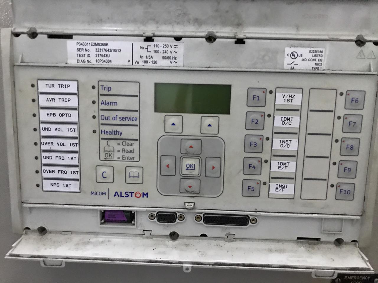
– We have a problem with the Generator Micom P343 that does not boot, please help us how to fix it, thanks
– Check the ribbon resistance of HMI to relay. We have faced the same and asked Alstom then after they checked and replaced the ribbon, and fixed the issue.
– Where is the ribbon?
– Open the front side of the relay then there is a connecting ribbon cable u can find
– This, is not Bad contact Ribbon the message is clear (Micom Booting) with Led Alarm lightning in red Fast
It’s like PC booting, I think it’s a microprocessor issue.
– We have faced the same problem in our reliance industries Jamnagar plant and Alstom itself give us a solution and change all the ribbons. Micom rebooting issue may be from the HMI problem/relay power card problem but if it comes even after replacing HMI look forward with manufacturers. It’s not just like pc booting issues. There is no chance of error in the relay or bugs like a microprocessor.
– I might be wrong but I share what I experienced with the same problem.
– Any vacancy for a Facilities Manager
– How do I determine distance characteristics in the L90 GE relay? do someone has a commissioning manual for L90 relays?
– I want to know what you guys as an Electrical Department are doing to fight COVID-19 in their workplace.
– 132kv circuit tripped showing R Y B phase and zone 1. And the same circuit is energized from another end at no load. Also, no fault was found on the circuit during patrolling. What will be the fault? Distance Relay type Micom P 441. It could be transient or pic up fault
– Does it show any distance in zone 1?
– Grid staff is not too efficient to check the fault recorder. I will go to check it tomorrow and will discuss it again
– What is the status now does the line charge from both ends?
– Only from another end at no load
– Sir but usually these transients will be blocked by numerical relays rights
– I think it may be DC grounding
– Check the fault recorded to see the fault current and voltage
– Lighting
– Depending on the magnitude and relay Makes. We have had similar invent without any trace of a physical cause
-can you share with us the Comtrade file
– What is the standard setting of the characteristic angle for directional overcurrent phase and ground (67/67N)?
– does somebody has this relay technical manual ABB PCD for the recloser?
– Hi anyone has a static VAR compensator (SVC) protection scheme that can share?
– What is the standard setting of the characteristic angle for directional overcurrent phase and ground (67/67N)?
– For typical distribution networks (up to 33 kV), I set it to 30 degrees. For sub-transmission/transmission, I set it to 45 degrees, between the current phase and voltage polarizing quantity.
– However different scenarios may require different angles and have to be worked out.
– This angle for directional phase overcurrent? What about the angle for directional ground over_\]\]\]]]\\]]\current 67N?
– Are there any references for how to make the setting for directional phase and ground overcurrent 67/67N?
– I would typically read the relay manual, And use the default recommended value. The actual math behind setting them can be very tricky.
– Which relay are you using?
– Sepam s40
– The application is two parallel Transformers
– What’s the voltage level and how far is the relay from the supply transformer?
– From experience, RCA is 20~40
– For 67N, the value is dependent on the type of grounding. Please refer to NPAG, it was clearly explained there
– Anyone has a digsi4 Activation Key? And for 67, if I am not mistaken, RCA is set based on the impedance angle of the system
– Anyone tested Transformer DIFFERENTIAL 7SR242 DUOBIAS. I have some doubts about bias characteristics!
– This is the complete manual, but the bias equation is not clear on it!
– Does anyone here got any information about ct accuracy class 0.1 PL 270 R6
– I want to know knee point voltage and resistance
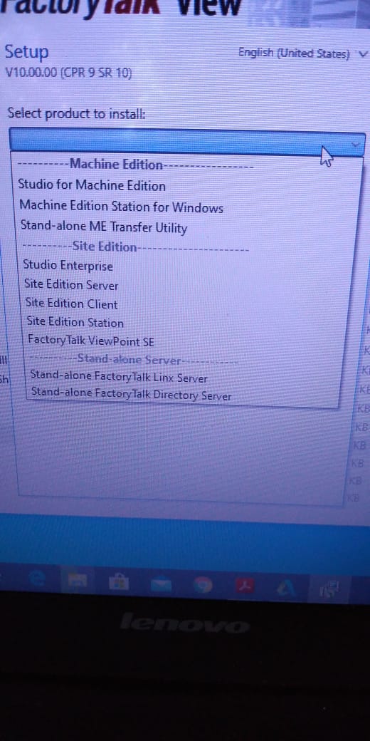
– Install Studio Enterprise this is a combination of all SCADA & it will work as per your licensing
– Does anybody here has experience with Toshiba relay GRL 200?
– I want to ask about the IO config
– Why don’t you Let the admin look into it? Please send me any study material regarding AVR
– For a substation
– Little emergency for my undergraduate project
– I can send you the datasheet of Engine AVR
– ABB Unitrol 1000
To join our protection relay WhatsApp groups, please send interest on Whatsapp: https://elec-engg.com/whatsapp-group-for-protection-engineers/
– I have to change CT/VT ratio in an Elster A1800 energy meter. Already got established communication with the meter via Metercat 3.5 software. I believe CT/VT ratios can be changed via the function “Program” but I am not able to proceed as everything at the “Program” popup window is grey (not editable), I request you support me in changing the CT/VT ratios.
– You have to enable changing xt ratio on the parameters function
– There is no Parameter menu in Functions? please clarify in detail or send a snapshot
– Hi Guys, I have a question for the 220KV level, which is suitable for either CVT or IVT(PT)? And why Usually we are adopting IVT(PT) in Andhra Pradesh India
– CVT always
– Sir can you please support your statement As we have observed the drift in secondary voltages is more in CVT compared to IVT over a time span
– Mainly installation reasons. they are lighter, cheaper, and Safer (transfer of emf when a fault occurs) as there is no direct connection to the primary voltage source.
– Can you explain how does the voltage drift?
– Deterioration in the capacitance levels throughout operations results in variations in secondary voltages Can’t that be fixed during maintenance? (Note: I don’t have any experience in maintenance and operation Even I don’t have any experience in Maintenance. But I am not sure we can improve this ineffective manner)
– CVT for transmission circuits or High Voltage i.e greater than 66kV and IVT for distribution circuits 33kV and below
– Moreover, we are mostly using IVT in 220KV levels also so, I am not aware of fixing methods. I believe it’s a cost trade-off. In India IVTs in 220kV class are more affordable than CVTs. And yet you may see them actively used in 220kV stations where the transmission system is at 220kV level. This is because the same CVT would be used as a coupling capacitor for PLCC communications as well.
– That’s my understanding
– Why when we calculate short circuits at transformer secondary we should consider no-load ph to phase voltage not rated voltage?!
– Yes.CVT is more affordable to be used since the consideration of its(equipment) isolation to H.V.
– Yes, we can track and analyze its dissipation factor( Tan Delta measurement)
– Which position?
– This is an AVR relay from ZIV bringing.
-anyone has the pin configuration of this relay?
– If you mean bias setting, then I would say it has to be calculated based on the transformer parameters
– Hello everybody, good morning. Do any of you run the digsilent program?
– What /which are the switching operations and commissioning procedures of HV / EHV equipment considering the safety rules of power system operation?
-P94V Undervoltage relay showing continuous trip, but no alarm present and all functions disabled, need technical support .can anybody please help?
– Go to view record and reset led Did, but still not going
– To increase the contact Resistance with the Ground!
-To minimize step potential?
-yes
Our completed Courses:
- IEC 61850 Configurator Training (4 Hrs)
- DIGSI 4 Offline Video Training (3 Hrs)
- DIGSI 5 Offline Video Training (7 Hrs)
- ETAP VIDEO Training (5.5)
- PSCAD Video Training (4 Hrs)
- PCM 600 Video Training (3 Hrs)
- MiCOM Relays Training Package (4 Hrs)
- Testing and Commissioning of Protective Relays
– Why stone and whether it’s the only solution?
– Cheapest
– Another reason stones are used is because it helps in the fire. mitigation, especially where oil traps/ sump pumps are not available.
– The leaked oil will have less surface area exposed to air that can burn, thereby reducing the fire hazard.
– Weather dry sunny temp 35c approximately Fault 132kv lighting arrestr and HV bush of power transformer 20/26MVA damaged
– 132kv CT side clamp
-Counter of lighting arrestr
– Lighting arrestr
– Structure damaged After fault jamper
– Analysis as per our senior-most retired chief Engineer such type of fault occurs due to delay of lighting arrestr counter delay. This type of fault occurred in Pakistan time by a time when lightning arrestr having counters are installed. Due to the delay, the HV bush of the power transformer was also damaged
– Did the Hv bushing pass the lighting impulse test?
– At the time of manufacturing or now
– Bushing may be damaged due to pressure of conductor available 132kv surge arrester if required plz context 03214484444
– I wonder if you have the fault recorder of this lighting surge impulse on your relay
– Are there any lightning arresters at the top of the transformers firewall/ other location?
– What’s the fault in the protection relay or fault recorder?
– Ds agile documentation please, guys how can I get cooling oil for a 1000-volt transformer
– What is the relay saturation of the IDMT curve in sepam T80 and S82?
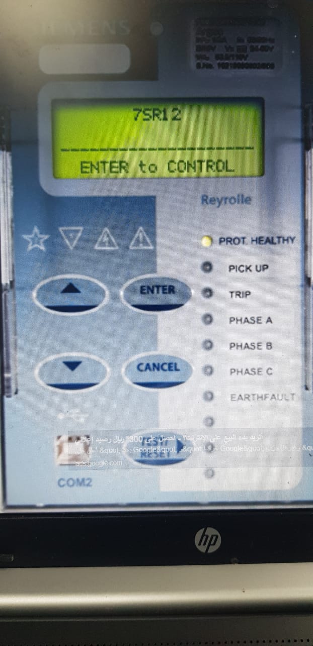
-Any have experience In Reyroll Relays.! I need help with how to change the “Out of service mode”.
– We need to do an 87L test, as you can see in the secondary current to relay is very low 0.044A. We did a second injection for the GE L90 relay and found it doesn’t read 0.044A. Value is fluctuating and gets stable at 0.1A.
– why the 51N protection of the REF615A relay operates in an almost constant time of 0.06 seconds
– reviewing the operation curve the minimum operation time is 0.02 seconds at least the first 3 tests would have given me the correct value
– check the other seating. Check the type of curve selected in the relay, Whether it is time or IDMT
-1 group setting might be clashing with another one, check all stage settings group-wise.
– Work Is for Automation Visit in Kolkata. Just visit the site in Kolkata only people from Kolkata plz contact me.
– A Power distribution full project including the design of LV and MV component
– 40mva x-mer tripped on differential during charging of 33kv feeder with Idr= 0.49pu, Idy= 0.50pu and Idb,= 0.53pu.
Both sides LA have physically verified and found ok.
– Did you check the %of Harmonics during charging from the DR?
– please do a stability test and after that examine the results.
– might anyone have the design book of transformers with CRGO steel core and amorphous metal core
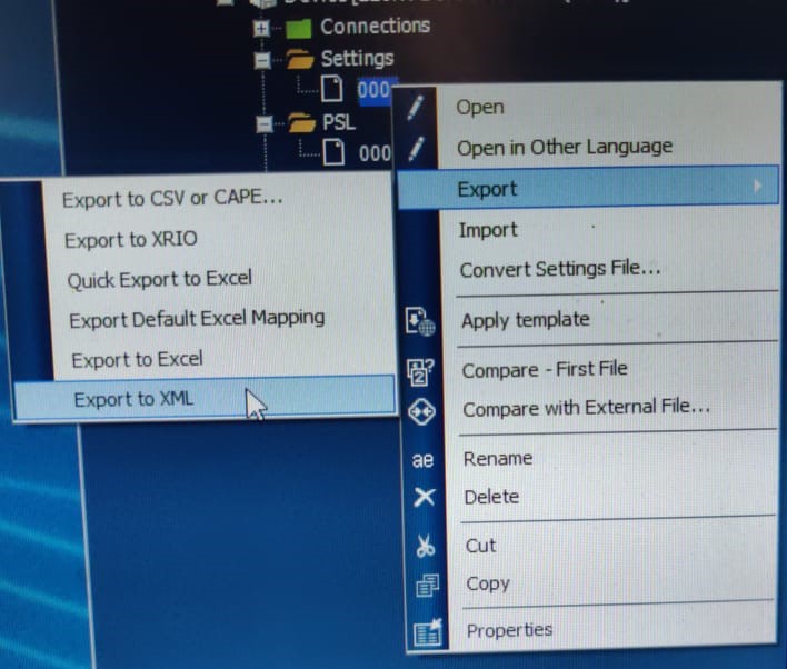
– Please guide how to reset DR full alarm in DPR Micom p442 Schneider Electric
– Maybe you can right-click on the device and select supervise device
To join our protection relay WhatsApp groups, please send interest on Whatsapp: https://elec-engg.com/whatsapp-group-for-protection-engineers/
– Anyone has a VALANCE book on “How to Test Breaker Failure Element Logic”?
– I have a problem with Micom P443 for Distance Protection. I have a problem with System Checks for Autoreclose, anyone can tell me what is the difference between CS1 Close Enable dan C/S AR Immediate?
– Cs1 close enable is the setting of sync check on which you want to recloser the circuit breaker like on Live Line Live Bus or Live bus Dead Line or Dead Bus.
– If you enable c/s AR immediate then it means that if during the dead time system check conditions are met then it will reclose the breaker without waiting for the remaining dead time period,
– Like for example if dead time is 1 sec
– And system check conditions are met during 0.6 seconds of dead time, then the relay will give reclose command without waiting for the remaining 0.4seconds of dead time. But you have disabled the system check conditions on shot1 which means it will reclose the breaker without looking into any system check conditions,
– Sys check on shot 1 should be enabled too.
– Hi Guys I have a question: what is the problem with a 3phases motor run by A frequency driver, if I want to run it very slowly for instance at 4HZ normally it runs at a modulated Frequency variable between 50Hz and 0 but what happens to a very low frequency?
– I know that it will run slow, but it will warm up a lot right? but more than that what will it happen? somebody, some documentation to explain this phenomenon?
– It depends on the loading. The higher its loading, the more power is needed to turn the output torque. If you don’t have a load, just make sure your lower frequency setting has a minimal current to move the rotor otherwise, it will overheat.
– I even reinstalled my windows not going, I checked the internet settings also.
– how we can develop an HMI screen of operator name tag id selection in Schneider Vijeo Designer Basic HMI software
– Can Anyone suggest or provide a link for low-cost alternatives for moxa U port 1150 type connectors with similar capabilities?
– USB to Serial converter
– Does anyone have sft sav diagnostic software for the Sepam relay?
– Does Anyone know about selec Twix-2 PLC communication with Schneider HMI
– Please have someone ever configured SEL 487B busbar protection?
– The SEL Technical Support Line is available at +1.509.338.3838
– does anybody here has the SUE3000 configuration tool
– Some examples of End Fault Protection with SEL 487B?
– Anybody can please share with ME Schneider Software SFT SAV?
– what does this number means 6000 of this RCD?
– It can open currents up to 6000A. 6kA
– Note it’s RCBO not RCD
– What s the difference? Because some tell me it is the max number of trips. RCBO stands for residual current circuit breaker. It can open faults up to 6000A. It can be used for short circuit protection as well as sensitive faults of 30ma. RCD is a residual current device. It’s used only to pick up sensitive 30ma faults. They can’t open full short-circuit currents. -Think of RCBO as RCD+MCB
– No it’s the rated fault level.
– We have the following problem with ER making DUOBIAS relay for Transformer differential protection
– Can anyone guide what to be done with this?
– Hi anyone tested the commissioning motor differential protection relay procedure please Sharing
– Short circuit level for this device
– This kind of error shows in sverker 900 Megger relay test kit anyone has an idea what is this?
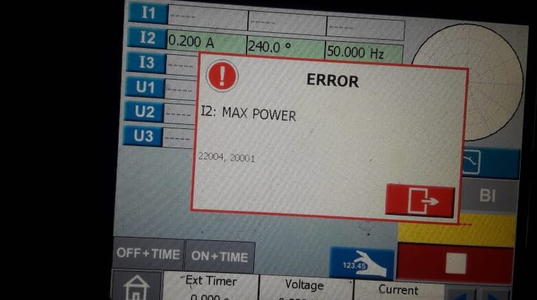
– Maybe you could try to restart the device. And try jumper each phase RST to the neutral phase.
– Jumper are arranged like this is it ok?
– I have restarted the kit but it not working
– Jumper I1to neutral, then I2 to neutral, and so on. Simultaneously inject a small current to monitor the device voltage ports are also not working
– How about the current ports?
-They are also not working
– Make sure when you start the device the knob selector is in an off position.
– Check the fuses too
– Does anyone know if you can force or simulate voltage on an ABB relay? That is, without using a device like Omicron
– someone helps, how can I test the GE L90 diff relay as a stand-alone without connecting with another one? You can only force digital outputs and simulate inputs. You can’t force analog signals such as voltage and currents. You need an external source
– I’ve never dealt with this relay but If it is for line differential, chances are that you’ll need two relays. the receiver and transmitter
– But you can still use the primary injection method to do the testing
– Do you have to test line differential?
– You can go to setting, testing, channel test, and loopback. Inject currents, the relay will consider one current as local and one as remote
– Hello guys, I’d like to ask maybe some of you ever test this type of relay.
– Where can we find the tms
– I think tms is 2
– TMS is nothing but a round dial
– Yes it is 2
– In this case, it’s 2
– for ref relay input problem. Ref620
– From the drawing, check the terminal point associated with this input. Isolate it then troubleshoot that circuit to find out where the “high/positive” signal is coming from
– why does inside relay see this message drawing as not a problem?
– I am working with a 2X300 MW thermal power plant in India and our 400 kv switchyard is having Alstom MICOM P 441, and REL 670 for protection also for the generator we are having siemens make 7UM622 and MICOM p345.
Is there any standard that speaks about the frequency of relay testing?
– Normally frequency of Numerical Relay testing depends on the utility practices.
– In our utility, we do it annually. But in my opinion, it is not required annually.
– Numerical relay can be tested for 5 years once. Scheme testing can be done annually.
– anyone has a cracked version of IED smart or IED scout for the IEC 61850 simulation?
– How to do scaling of this pressure sensor
– these transmitters are of a fixed range
– 615 series?
-RET620
– try to use a new project. if still like that try to factory reset the IED but if it is still operating

Elec-engg.com
join our protection relay WhatsApp groups, please send interest on Whatsapp: https://elec-engg.com/whatsapp-group-for-protection-engineers/
– How to connect GPS to this siemens relay 7VE632
-synchronization via IRIG-B
– someone assists me with CPC 100 software.
– You either need IRIG B port on the GPS receiver or you need NTP to IRIG B converter
– Please find below the parameters you are expected to use as discussed with RTM;
Reactance = 0.2215 ohm/km
Inductance = 0.20808 ohm/km
Suseptance = 0.07573 ohm/km
Distance = 313km
– Please how can I find the positive and zero sequence impedances from the above parameters thanks
– 400 KVAR 90 UNITS. 132KV CAPACITOR BANK. neutral CT 5/5. 132kv CT 400/5. Capacitor protection or unbalanced relay current setting? Relay type SPAJ 160 C
– Normally Unbalance protection has one special other CT different from CT 132kv phase or CT neutral but if This CT 5/5A is just for SPAJ protection we adjust the setting unbalance between 10 (..)20% In for nominal current this CT 5/5A
– Please explain the working of the reverse power relay at the consumer end for the small hydropower plant with a declared capacity 24.75 MWWhat is recommended Characteristic angle for Directional Earth Fault protection (67N) on SEPAM
-Sepam relay is on the closed-loop network.
-System grounding: resistance grounded (Two NGR Prallelled: 2x800A: 1600A).
The type used for 67N on Sepam: Type-02 (the protection function uses I0 vector magnitude).
Residual Current input on Sepam: Calculation of Summation three-phase current (not residual CT).
If anyone is interested in ETAP discussion Whatsapp group, send ETAP on Whatsapp: https://elec-engg.com/whatsapp-group-for-protection-engineers/
– I want to know if my raw data for the sensor is 0 to 32767 and I wanted it to show in HMI in the format of 0 to 100 bcoz if in system sensor mistakenly gets faulty or I have to replace the sensor and the sensor of any other company in my system, so due to this I can change from HMI raw data in the format of 0 to 100 is it is possible?
– Hello, Micom p-243 protects the compressor after start 15 minutes then trip. The indication in local HMI (motor fault alarm )but in the protection relay no indication but became an open position. When I go to the record I see this in the pic
– I do isolation resistance for the motor by using 5kv meggar the result was 4Gohm
– In HMI how to create an operator name error
-It’s over Current, what’s your starter motor current start pick and protection Micom configuration?
– Respected members, Please guide me on how to carry out the Hi-Pot Test/Dielectric strength test for 22kV 3ph Breakers/Bus bar.
-If the available source is DC for testing, how much voltage is to be applied, and are any references of the standard for the same?
– How to write scripting language for 0 to 50 Low and 50 to 100 high values in C programming for HMI?
– on Nari pcs9611 relay, when powered on it displayed sub-supervision Alarms. Alm-device, Alm -time sync.
How can I cancel?
– set the time synchronization to off instead of sntp
– Under settings?
– under device config or communication.
– Does anybody has ZX0 ABB switchgear O&M.manual
– Especially Gas handling procedures
– HB 600-05 en
– HB 605 Gas handling Manual for ZX0
– I tested my lightning arrestor for 11KV after removing it from the line and the IR value was 400 meg.
– A few minutes later I tested it again the value was raised to 15 Gig.
– Please I need the manual of Siprotec 7SA87
– Hello everyone, could you help me with the function of the TC1 on the delta winding?
– It’s a current transformer for the winding temperature gauge
– someone knows what is the difference between I> and I>>?
– I> is the short-time protection setting and I>> is the instantaneous protection setting of the overcurrent relay
– Can somebody tell me what happened if the tripping coil resistance and a closing coil resistance of vcb are the same? then there is any impact on the performance of vcb?
– You can return to the datasheet of the circuit breaker and closing and tripping coil, you can find the standard values of the resistance of the trip and closing coil and compare it to the measurement
– I just want to know the theoretical answer Behind this.
– From an electrical engineering point of view
– closing coil resistance is designed much less than tripping coil resistance to having a stronger magnetic field
– Yes I know it is designed, but my question is if they are the same then, what happened?
– does somebody here have some “how to configure Modbus protocol in SEL relays” document or some kind like that?
– Someone has a method statement for Testing CVT Tan Delta

-Does anybody have a project for the RED670 relay?
– Anything, in particular, you are after !’vv?
– Current line differential relays fairly straightforward?
– Anyone knows what is the problem when a source (power plant) transmits power to a substation, then the neutral current monitored in the power meter is a bit higher than normal?
– I know that It means that there is an unbalance current in each phase. But what else can be that causes the phenomenon?
– The P.F on phases R and S are lagging 0.9, but phase T shows a leading P.F.
– In case it’s an internal fault, just assume that the 87 T relay and Ref relay will trip.
– your understanding is correct. But apart from it, if primary Overcurrent (50/51P) works, it will trip the CB 150 kV, and how about the CB 20 kV?
– Is it required to trip the CB 20 kV too?
– 87T trip, REF not really, depending on the fault. PP fault or 3P internal fault won’t initiate REF
– To isolate the power from the LV side too, in case of bus section on the 20 kV side is closed
– Depends on the control scheme we use in most of the cases we adopt if HV side CB trips on protection LV CB also gets a trip, and REF is more sensitive for earth faults in the differential zone. If it is an earth fault REF trips faster than Diff.
– I think that 20 kV CB will need to trip too to prevent reverse power from the remanent voltage (power) at Bus 20 kV side. But if there is a remanent voltage on the 20 kV side, is it possible to induce a voltage in the primary winding to create a current?
– Since you have NGR, an earth fault close to neutral may not be detected by REF.
– Percentage of the unprotected zone can be calculated based on relay settings and CT ratio.
– Yes. due to the resistance, the sensitivity will be limited.
– Have everyone ever tried the induced voltage on the secondary winding of step down Transformer i.e. let’s say 150/33 kV. How about the primary winding transformer, does it will generate a low current or a harmonic current?
– Actually, fault moves towards the source. In actual LV will not trip because the fault current will move towards the source side (150kv) side but if inter trip function is available then LV 20kv side will trip too
– Anyone knows about the calculation to get the value of Z1 Sensit? Iph>1 ?
– Fault current should be above this value to identify zone 1 or zone 2 faults
– I got it. But how to get this value?
– Okay. I have found it was 1.2 x CCC / CT Ratio
– CCC indicates which value? please clarify I doubt the Current Carrying Capacity Of the conductor
– In Distance Relay
– Anyone knows the CB IS( In-Service) Time function?
– Since I close my CB then the IS time starts to count to set AR Block
– If CB is manually closed then after this time CB will be considered in service and the Auto Recloser function will be enabled too.
– But why it AR block indication appear?
– After the CB IS Time starts to count. Still struggling on this distance relay
– Because during CB IS time AR Function is disabled to block the AR on SOTF fault, change to ABB REL670
– What type of relay is this one?
– P443 Micom
– does anybody here has a p14d Modbus register
– who knows the ZIV default password
– Any ZIV relays specialist
– Hello all, does anyone has a GRL 200 Toshiba Line Current Diff Manual Book?
– Four corner numbers 7931
Join 20 WhatsApp groups for protection engineers
20 WhatsApp Groups for protection engineers
- WhatsApp Grp 01: Protection Relay – General
- WhatsApp Grp 02: Substation Automation – General
- WhatsApp Grp 03: Transmission line protection
- WhatsApp Grp 04: Transformer protection
- WhatsApp Grp 05: Motor protection
- WhatsApp Grp 06: Generator protection
- WhatsApp Grp 07: Overcurrent and Earth Fault Protection
- WhatsApp Grp 08: Busbar protection and Bay controller
- WhatsApp Grp 09: Breaker protection and control
- WhatsApp Grp 10: Protection Relay Testing and commissioning
- WhatsApp Grp 11: DIgSILENT
- WhatsApp Grp 12: ETAP
- WhatsApp Grp 13: PSCAD
- WhatsApp Grp 14: IEC 61850 configuration
- WhatsApp Grp 15: Switchgear GIS & AIS
- WhatsApp Grp 16: GE Relay Configuration
- WhatsApp Grp 17: SIEMENS Relay configuration
- WhatsApp Grp 18: Schnider Relay configuration
- WhatsApp Grp 19: SEL Relay Configuration
- WhatsApp Grp 20: ABB Relion configuration or more services
send a message to our WhatsApp support number, (Click)
Sample discussion:
– I have a Zivercom relay for the Tap changer. everything looks fine but it’s not Tapping who can assist tanks
– is anyone familiar with Siemens Siprotec 4 7SD Line Current Differential Relay? For example, if one end of the relay is selected in Commissioning mode(test mode), will the remote end relay differential protection be in commissioning mode or test mode also?
– Commissioning mode at one line end will not turn on commissioning mode automatically to another side. Plus commission mode is completely different from the test differential mode.
– Can you explain a bit more about the test differential mode?
Does turning the test differential mode at one end also activate the remote end’s test differential mode?
– Anyone REM620 relay this message what problem
– Anyone has the actual standard IEEE 485 or an excel sheet? I need to size the substation battery charger, please!
– IEEE 485-2020?
– Does anyone know what these signals are used for?
– Apparently, they are permissive to Switches
– RECEPTION RRR, RRA, RRX, and RRY
– the arrangement of the substation is as follows
– Have anyone tested Cap bank differential protection in Siprotec 5 7SJ85 relay?
– constantly get this error while writing to the IED
– delete the HMI page first
– do the license update tool
– Does anyone have software for this relay micom2.1?
– I have found Micom software if anyone can give Ziv software as well plz
Our substation incomer feeder is tripping downstream and upstream without any fault when switching on outgoing feeders.
– Please suggest any ideas to solve the above-mentioned issues
– What fault was recorded by the relay?
– There is no fault on the relay but upstream and downstream are tripping when switching on any outgoing feeders.
To join our VEBKO WhatsApp group, plz text our support team on WhatsApp (Click)
– Any circular regarding the fair service life of various testing equipment in the power sector.
– Hi, has anyone ever replaced these manual annunciator window tiles with a 3rd party tiles? or other alternatives?
– We are facing this kind of rebooting issue with the AREVA Micom P742 peripheral Unit for busbar protection. Does anyone have any idea regarding this issue? How to overcome this?
Protection Relay Discussion Group in Telegram: https://t.me/joinchat/Cmyg2FiXX-qlTYqyXQ_pjg
– Can we use a 10 ac drive on a 15 hp motor?
– 12.5 hp drive on 15 hp motor
– Hi, do you guys ground the shield of control cables at both ends or only a single end?
– Single-end
– How about for CT VT Cable?
– May I know if would there be an issue if we use a CT with a high Burden (15VA for example) for a protection relay (microprocessor type). For the old mechanical type, I understand that the CT needs a higher burden to drive the armature
– when I turn on the generator in this panel my generator has an unstable frequency but when I operate it manually the frequency stabilizes. what may be the cause of this?
– Is your gen-set in synch with other gen?
– no sir.
What is voltage?
– plz check the gain & another setting for your operator panel
– 460v
– there is no problem with the engine & gen-set itself it is the only problem with the operator panel feedback signal which will be generated as per setting
– Cause freq regulation is in the generator itself not in Woodward
– we try to bleed fuel on the generator. but nothing happened
– I thought Woodward only does parallel synchronization and some protection functions but is only using small loads that’s why we don’t sync our generators.
– I looked at the manual for easygen. There is a function of frequency control. I have the same system
– But never got time to check every function in Woodward.
– I do check some functions but the configuration has a password. the management told me that the supplier has the access to its unit.
– does anyone knows about arc resistance and tower footing resistance value for the 765KV transmission line?
– I need to disable goose controls in the REF 615 ABB relay. Is it possible from HMI?
– who can assist me with an IED scout that’s licensed REG630 how to test method DOPPDPR function Power Angle setting anyone to have a formula
– Could anyone be having transformer test guides preferably based on megger make test equipment?
– Paci’s configurator from Schneider, can anybody have this software if yes kindly send me the link, it’s urgent please help me
– Somebody has REX640 TERMINAL DIAGRAM?
– Does anyone know how to choose a zero-sequence transformer?
– In the VAMP300 relay display LED continues to glow without assigning, without mapping with DI points. what is the issue please kindly suggest!
– Need help in ABB RVC APFC Relay programming.
– If anyone has a license for REB500. Can help me, please?
– ABB normally does not release that license that allows you to configure
31etap 12:00 – abb pcm600: The user license there isn’t much you can do with it.
– Kindly someone tells me that in C264 Relay, how to change synchro-check parameters and find the passwords?
– Connect to Cat tool to these devices n check network parameters. Trying to read the setting but the reading takes a few hours. Are there any solutions?
– I assume some delays in the network..try connecting them one-to-one if possible.
– Try to reboot the relay
– what could be the problem if Generator Shuts Down on High or Over Frequency, Over Frequency Runaway
– If you are connected to the grid Burn the rotor due to induced currents. If you are in islanders mode: damage the connected equipment.
– is it ok to run a generator that varies 59.9-60.1 frequency?
– Trying to read ABB RET 670, but the messages show up like this
– Any insights into this problem
– Does anyone knows how to add delay time in VT Fail ABB RED 670
– Not very sure but An inconsistent state means the current values in PCM are not reflecting the IED values. If a reader does not resolve this try to see if there is a new version of PCM.
– 132kV transformer HV breaker was closed on NO load and the LV breaker was open, but suddenly differential relay operates and gives a differential trip. In the fault study, the HV side current was 860 Amp. Somebody tell me what could be the reason?
– For how much time the transformer was on no load? 132/11.5kV?
-Approximately 10 to 15 minutes
– MVA?
-132/22 kV (wind power plant)
– There must b some issue,
– So this is not inrush
– Do TTR and winding resistance,
– If it is the newly commissioned plant then the issue will be in the relay setting otherwise check transformer winding. do the IR.
– I did an excitation test @ 10 kV and the results were OK.
– Plant is in operation for the last 4 years. You will have to do TTR and winding resistance to diagnose the matter, Hope you will get the problem by doing these tests,
– Any mechanical protection PRD, BUCH has operated. Did u retrieve the fault records from the relay?
– TTR?
– turns ratio test
– No trip from mechanical protection.
– In the fault record HV current was 860Amp and LV current was 0 amp.
– Check the CT ratio adopted in the differential relay and what was the differential current setting adopted and actual current during the relay operation?
– Transformer turns ratio
– 860AMP WAS A SINGLE PHASE OR TWO PHASES OR IN 3 PHASES?
– In 3 phase
– Did you check the lighting arrester AT 132 KV SIDE?
– Yes surge arrestor can also be damaged or weakened, as you are using Yard CT for Differential protection
– do also check your HV arrestors
– Can anyone help me with the PACiS configurator?
– Physically that was OK, for counter I will check
– Do hipot test of arrestors, which might be differential tripped because of arrestors, If u have a secondary injection kit like Omron or Freja plz do the secondary injection to know that there is no problem from the relay side.
– can I ask why my plc doesn’t read flow?
– Check that the analog signal is reaching from your flow meter to plc?
– Check 4 to 20 amp signal
– Hello guys, does anyone know how to avoid distance trips when VT Fail occurred on 3 phases in REL 670?
– Anyone has any material for Artificial intelligence application in Protection?
– Pls help me how to install PCM 2.10
– Strongly recommend installing on virtual machines
– After 3~4 different versions, they always conflict and give errors.
– I run different virtual machines on the ESXi hypervisor.
– I need help analyzing this Disturbance Fault Record whether it is due to Lighting or Flash.
– It was a fault on Line Diff and Reclose on Phase R.
– Plz tell me, what is relay coordination and what its functions are.
– Line auto-reclosed successfully?
– We have 50/1 5p15 CT installed on a 33 kv feeder whose fault current initially was very less but now the Power supplier has installed a 50MVA transformer with 11% impedance
29etap08:55 – abb pcm600: And fault current is almost 8000Amps, I believe I need to upgrade protection CT to meet the high fault current
– Can anyone suggest What’s the 33kv fault level?
– Now it is 8000 amps. Fault current level 50 MVA transformer installed at state electricity board substation and we are consumers with 33 kv feeder voltage
– 50MVA 220/33 KV star/ star connected transformer 11% impedance
– Is the ct used only for over current and earth fault?
– Yes 50,51, 50G, 51G
– Strictly speaking, I would put 200/1 5P40 2.5 VA. However, if the relays have CT saturation detection, you could go lower.
– What’s the relay being used?
– P127
– Do you have the CT test results? In particular the DC resistance of the CT.
-Can you give your consideration or calculations for this selection
– So you need an accuracy limit factor of 40, with a low burden.
– you won’t need much burden as the relay is numerical and installed inside the switchgear
– Your existing 50/1, 15 VA may actually work if you knew the DC resistance.
– Do I have to check with the CT testing kit??
– I believe CT supplier should have this information
– Yeah if you have test equipment (Omicron CR analyzer or similar) that should be easily possible
– That’s possible, however normally the manufacturer will not specify the DC resistance for 5P/10P class acts. No harm in asking them though
– CT’s Analyser
– Ok I will check with him today, as I don’t have an omicron kit available nearby That is the only option I have
– How do you coordinate DC resistance with fault current?
– So if Rct<= 1.75 ohm, you can use it For a 50/1 A ct this may be achievable.
need to Replace 33 kv side CT with, 1000/1A, 5P10,15 VA With this approach, I’d reckoned to check the pickup values.
– Ynynd1 And tertiary (delta winding) are unloaded?
– Then no issue transformer will follow the system phase sequence,
– What is the difference between IN-HV Deriv Angle and IN-HV Measd Angle on monitoring online?
– Derived means the neutral current has been calculated by summation of IA, IB, and IC whereas measured means the neutral wire of ct secondary is connected to the neutral element of the relay, and it is being measured,
– What is a dead zone in protection??
– Dead zone is the Zone between CT & Open CB. It’s the point not seen in the zone of protection that of a relay. If a fault occurs at this point, the relay will not issue a trip. Usually between CT and breaker
– IN HV derive is neutral vector calculation, meanwhile In HV measured is a neutral REF winding
– We cannot say it is neutral ref winding until we see the setting of the relay,
– the setting of the wiring diagram is right. The relay and schematic drawing setting depict the connection of the ct secondary wires with the differential relay.
To join our WhatsApp groups, plz text our support team on WhatsApp: https://elec-engg.com/whatsapp-group-for-protection-engineers/
Our completed Courses:
- IEC 61850 Configurator Training (4 Hrs)
- DIGSI 4 Offline Video Training (3 Hrs)
- DIGSI 5 Offline Video Training (7 Hrs)
- ETAP VIDEO Training (5.5)
- PSCAD Video Training (4 Hrs)
- PCM 600 Video Training (3 Hrs)
- MiCOM Relays Training Package (4 Hrs)
- Testing and Commissioning of Protective Relays