
Join our problem-solving discussion groups (Click)
– using the DCL Sinha 197-1-1 temperature controller its output is given to the fx2n-4ad converter, its output is given to the PLC (Mishbushi fx2n-80mr) but in HMI am not getting the proper Temperature, What is the problem?
– I think it isn’t related to the HV substation.
– It is not related to the HV substation. This belongs to a thermocouple for temperature detection/measurement. Need some calibration
– It’s already shown that the temperature transducer gives 4-20 mA to the PLC Analog Input. You have to make some calibrations to divine this 4-20 mA signal.
– PLC Fx2N communication with HMI already use digital data, it’s not analog so you have to make sure at PLC Side, how the programming work. I mean, how is its calibration? sometimes do to x-factor you need some increase or decrease the coefficient factor at the PLC program for detecting the temperature, but before you play on the PLC side, you must make sure that the Temperature Transducer is working well, and all the connections are properly installed, including the cable shield, and cable track
– Please make sure the control cable didn’t cross over or beside the HV cable? some induction because this installation can cause distortion.
– I wanted to open the gate valve electrically.
– Use motorize valve.
– Use the simulator from that u will get 4 to 20 mA output.
– Hi I need some support on ABB RTU560. Trying to map -1040mW to +1040mW to the AO card, the AO card is sending is out as: -20mA to +20mA, but the DCS is expecting a 4-20mA range. Any idea how to config this in rtu560?
– Anyone in this group has implemented Solar SCADA, PPC & PASS for a large Solar power plant. I want to move the resister from one word to another work. Receive data from Analyser and want to show on display On MODBUS protocol, Is there any software available like Modscan?
– You can use products like Redlion to read from a slave and write to a master at a different address. (hardware and software required)
– what Slave and Master are you using?
– Hello, can you help, When do we connect the relay to the Switches and when do we connect it to the Gateway device?
– Is it possible to share the SAS diagrams of a power substation?
– Anyone has AB PLC software or its link please send me.
– We connect relays to switches for IEDs communication because all relays are based on the 61850 protocol. It will connect from the gateway device when we have to send our all data to the remote end?
– Yes it is possible through a router which is used for receiving and sending through moxa switches.
– If the relay communication is Modbus and the SCADA is Modbus also, why do we use RTU in this case? What is the problem if communicating SCADA with the relays directly?
– For Modbus TCP/IP you could communicate directly without intermediate RTU
– So, when I use RTU?
– If u have Modbus RTU devices and or hardwired signals.
– I am confused about our substation, we used RTU, but both sides are Modbus!!
– Which Modbus type?
– TCP/IP
– It is more efficient for a SCADA master to poll a single device (RTU, customize the Modbus map to have minimal gaps to optimize efficiency grabbing larger chunks of information in a single poll) as opposed to polling multiple devices (separate poll for each IED, possibly multiple polls per IED depending on what information is being obtained and wherein the Modbus map the information lives, assuming not using a custom Modbus map in IED).
– If you want to use a single-mode FO Cable to connect two RSG2100 Ruggedcom switches in two different buildings how can you do it.? There’s no ping when we connect and try
– How to check Modbus Communications?
– By Modbus mapping, software that is used for a particular device.
– We are using some fans with Modbus, and no one is working, HMI showing it is Modbus’s fault
– Check the continuity of the Modbus communication cable. Open the software and check the fault value shown in the Modbus block, so u can find the solution.
– what’s the difference between SCADA and HMI?
– HMI for operator level, the limited operation only performed (ex in HMI report script, continuous data logging is not) Scada. in SCADA everything is possible. check the polarity of digital inputs and outputs connected to plc and check to the ground.
Join our problem-solving discussion groups (Click)
– I need help regarding dc1040 Honeywell. What changes I must do in dc1040 to use rtd pt-100?
– You need to change its input type
– Which input do I have to put?
– I tried j1
– It does not show an option for dp3
– Not working
– Did you go into that option and set rtd dp1?
– Not showing dp1 option
I use an Emerson VFD on a motor vibrating grizzly feeder but have noticed that the motor windings burn every time the VSD trip on over-voltage. is there a logical explanation for this?
– VFD is faulty, giving 2-phase
– We have measured all 3 phases are there
– The VSD is showing an overage trip but when we checked the motors the windings were burn
– Maybe the less current, please recheck the phase.
– Yes but for a bigger size 250Kw motor. The motor was new and for 550V application
– It has been working like that for 2 years with no issues
– Check the time delay for tripping in the VFD, Maybe it’s on the high side
– Does it regenerate power during operation or ramp down?
– It’s during ramping down when we stop the motor
– 250 kW is too heavy power, Are you using break resisters?
– Difference between plc and DCS?
– There is not any documentation on how to size for that power
– When I’m giving 3 phase supply to this breaker Breaker not ON
– Check the supply of the closing coil and the closing coil.
– Not able to understand I’m sending you a diagram
– Here are a total of 6 wires connected apart from the power wire
– Can you check the supply at 35-36, 37-38?
– Check no supply coming before that 3/1 and 3/3 should be ON
– There is supply at S-T. These are the 3/1, 3/2, and 3/3
– Mean the secondary coil of the transformer?
– The top left corner of the 3phase supply
– RST From where the 380 V supply is tapped
– Also check the K10B NO contactor
– In diagram shows the supply coming from S-T but this is connected directly to S-T in the panel. That’s why the supply not coming in ST I’m sending you a photo
– How I can bypass
– Check with a multimeter, The supply voltage
– For what purpose it is used?
– 3-phase supply voltage okay
– I need to ON 3/3 transformer
– When is the step down in 24V?
– Is the 24 V ckt supply ok But not ON?
– Which one?
– Below the 380 V
– This one should be on but not ON
– This is the K10B how am I can ON this?
– Check the supply in 37-38.
– It should be 24V?
– I have Siemens s7 400 plc and its monitoring Siemens step 7 v5.5. I need to create different authorized levels to enter this software with a password. And I want to get a report on who is entering the software and what they did. Anyone has any idea please help me
– For the S7-400 PLC, it’s only possible to enter one password. This password will protect against changing the program. To do this, one has to right-click on the CPU from Simatic manager and then choose object properties, protection, and choose among the three options i.e. 1- key setting can be bypassed with a password, 2- Write protection, and 3- Read/write protection. Thereafter enter the password and write configurations to the PLC. Depending on the option chosen, the plc will protect upon establishing a connection to it. In terms of user activity logs, this can only be achieved from Wincc/HMI
– In SCADA or HMI u can create a different authorized level, In the program, u can set a password for plc,
And also you can set a password for all blocks u developed. What about Siemens logon?
– With this, you can. But not much sure, about simatic logon
– anyone knows any software for analyzing CAN protocol, like Modbus we have Modbus poll software.
– CAN runner is a CAN analyzer and diagnostic software tool built with the cross-platform Qt toolkit. It is a powerful tool for software developers and service engineers, providing advanced data monitoring and analysis capabilities.
– Monitor real-time data on the CAN bus. Analyze and catch problems on the CAN bus. View CAN bus statistics Use both standard CAN and CAN FD
Parse CAN protocol-specific data (such as CANopen and J1939)
Remotely diagnose CAN bus over Ethernet by connecting to WRM247+ remote device
– is it freeware?
– yes
– electrically how much different is CAN from RS485? I think both are serial communication with differential signaling electrically so what is difference should be only on data packets and frame structure that defines CAN as protocol correct? just like Modbus?
– CAN specifies much more than just the physical layer, whereas that’s all you get with RS-485. There is no standard way in RS-485 to decide who gets to send, what is being sent, how to know it got there intact, etc. CAN specifies complete packets on the bus, which include a 16-bit CRC checksum and one can argue that CRC and making those traffic regulations is a work of protocol and not the responsibility of electrical protocol or physical layer
– Since several protocol layers above the physical are specified with CAN, the logic to implement them can be built into off-the-shelf hardware. You can find small and cheap micros with hardware that sends and receives whole CAN packets. This hardware automatically takes care of packet start/end detection, collision detection, back off, retry, checksum generation and verification, and a few more capabilities related to dealing with hardware faults.
Join our problem-solving discussion groups (Click)
– How to connect Schneider c264 bcu and which software is used?
– For configuration of database SCE is required, For writing files to bcpu, CMT is used.
– SCE version and database should be the same otherwise it can’t be done
– everybody I’m looking for the latest version of pl7 Because when I tried to restore the program from the plc I got these messages
– By searching in the net it says that I must upgrade my pl7
– pl7 4.5 pro sp5
– I have tried to solve this problem without success. The module is the same as the one configured in the software still bringing this
Check if the firmware version on the module matches the one on Simatic Manager
– Check bus connector and check the wiring if the problem persists, replace the module.
– I replaced it with a new 1 and the problem was solved. I have changed the bus connector to cuvc and replaced the cuvc card itself but no improvement.
– Is the DP slave an ET station or what?
– Hoist drive And ET station has a problem also. This crane has been down for a long time now am trying to restore it
– 3 times we find the surge arrester failing (and we trip of course by 59v). It installed between generator 15kv and step-up transformer
How can I know the reason?
– Check if in these cases happened to submit load rejection. In these cases the voltage increases in the generator terminal.
Join our problem-solving discussion groups (Click)
Our completed Courses:
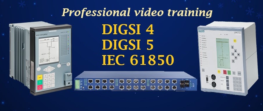
- IEC 61850 Configurator Training (4 Hrs)
- DIGSI 4 Offline Video Training (3 Hrs)
- DIGSI 5 Offline Video Training (7 Hrs)
- ETAP VIDEO Training (5.5)
- PSCAD Video Training (4 Hrs)
- PCM 600 Video Training (3 Hrs)
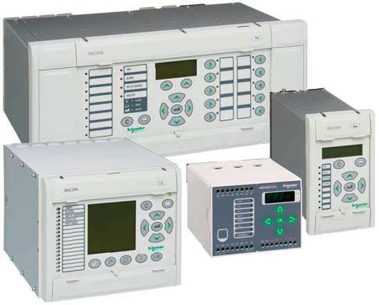
- MiCOM Relays Training Package (4 Hrs)
- Testing and Commissioning of Protective Relays