For joining our discussion groups: https://elec-engg.com/whatsapp-group-for-protection-engineers/

PROTECTION RELAY SYSTEM
elec-engg.com


– Who knows the REF stability procedure? Both the voltage injecting method And the current injecting method?
– When you create in the zone or out zone fault for REF stability there will always be a flow of current.
– Short Primary Bushing Phase R S T with secondary terminal shorted after CT. Then Inject One Phase Voltage, Then Current will flow through the Primary bushing and NHV. Inject current from low voltage side, in R phase and check for current (secondary current and display current in relay) at high voltage side.
Pl inject current outside the REF CT covering zones – relay should be stable (should not trip)

Reverse the R phase secondary terminals at TB(HV side) and take measurements ( display and secondary)
– What about lv side y,b phases? should be short or kept open?
– Open.
– Repeat for the Y and B phases. Then for R, Y B combined.
– Note that NGR must be shorted Or it would be burned.
– What if it’s a Delta star transformer?
– HV and LV CTs must-read values to short and reverse secondaries at TB.
– How to test REF on the Delta side if it’s available with an earthing transformer?
– I think this is the connection but I don’t know why we short ckt on the delta side two phases?
– Because a single phase-to-earth fault on the star side will get reflected as a phase-to-phase fault on the delta side?
– Is this shorting mandatory for star Transformers also?
– what if short all the primary phases?
– It’s only if we inject three phases, Current will also loop. we stability 3 phase then REF

– Creating the fault within zones – you can do this by closing Earth switches (outside the CT zones). Creating the virtual Earth fault through closing the earth switches (outside the REF CT zones).


DIGSI 4, DIGSI 5, ETAP, PSCAD, IEC61850, PCM600, Testing & commissioning, Generator protection

🌐 www.elec-engg.com
protectionrelay.com

– Do anyone knows how to do the AVR auto mode test on ABB RET670. The issue is over current blocking feedback that need to be recorded through goose with Omicron kit?
– Anyone can share the ABB REJ601 relay password to edit setting parameters
– Can we set CT ratio 650/1 in ABB REJ601
– Is there any option for the TCS circuit at Siemens SIPROTEC5 BCU 6MD
– it is urgent if anyone has information please share it.

For joining our discussion groups: https://elec-engg.com/whatsapp-group-for-protection-engineers/


– I found some mismatch between PCM and IED technical Key, Does anyone here know how to fix this?
– If you have the right connectivity package concerning the IED software version, then create the bay from scratch and collect. Normally it detects it automatically

– Does anyone have a Methodology for End to End Pilot wire differential protection for the cable? Please share Thanks in advance.
– You have to download it from the SEL website


– Can anyone tell me about the MIF II digital feeder relay GE Overload thermal relay setting detail of cooling time and heating time? model no GEK-106237Q

– Does anyone have Schneider electric relay SEPAM T82 RELAY technical catalog?
– You can download it from www.Schneider-electric.com.

– Which parameter (Measured or Derived) does the relay sense to trip the relay if the IN exceeds the setting? IN Measured or IN Derived?
– Check the Analog card whether a separate coil is provided for neutral.
Protection engineer user x: Which relay?
– It depends upon which factor you are using in settings.
– What is the issue? When I’m going to install PCM 600 v2.10 then this error will come.
– Which SQL Server is needed for PCM 600 v2.10?
– That’s telling 2014 express.

Protection engineer user x: Guys, If anyone has IEC 60870-5 – 101 & IEC 60870-5 – 104, then please send…
Protection user x: Is there any one user of the DEIF Controller?
Protection engineer user x: Anyone has an idea of IoS A & IREF N in ABB REF relays?
Protection engineer user x: IOS A & IREF N.
Protection user x:

– Why do we put an OLTC of the generator in local mode?
– Are you talking about the OLTC of Trs at Generation Station?
– Local it’s mean cannot access remotely, depending on operation requirements.


-We lost the password of the MicomP143 relay. Is there any option to reset the password?
– You need to contact customer care with security code device details


– Does anyone know how to Synchron the date and time of relay micom from the Serial Port?

For joining our discussion groups: https://elec-engg.com/whatsapp-group-for-protection-engineers/

PROTECTION RELAY SYSTEM DIGSILENT
Elec-Engg.com


– What is the IEC standard for relay setting coordination, the minimum operating time between two relays i.e. source & load?
– 200msec.


Our 2 latest courses are on the website. You can see details here:
🔸generator protection 🔸testing &commisioning

For joining our discussion groups: https://elec-engg.com/whatsapp-group-for-protection-engineers/


All Elec-Engg courses are available for you to take:

PROTECTION RELAY SYSTEM DIGSILENT
Elec-Engg.com


💠 DIGSI 4
💠 DIGSI 5
💠 IEC61850
💠 PSCAD
💠 ETAP
💠 PCM 600
💠 Micom
💠 Testing & Commissioning

💠Generator protection

💠Digsilent

💠 Busbar protection

🌐 Elec-Engg.com
🌐 protectionrelay.com

– What could be the possible cause of the increase in the current of one phase of a generator? My generator trips of overcurrent in Phase B. I have done all the checks on the generator and it seems okay.

– Is it possible to inject both 50Hz and 100Hz of two current sources in the CMC356 Kit?
– Yes, parallel sources 1 and 2 and use source 1 for 50Hz and source 2 for 100Hz.

– The above method should work for checking harmonic restraint blocking and tripping percentage. In my quick CMC, if I change 100hz then remaining all sources also will get changed into 100hz for harmonics.

– Right-click and select unsync.


– Can anyone explain the function of the three CTs on the neutral side?
– Possibly for generator differential protection. These CTs are connected on the main winding of Gen. However, on the neutral side of Gen and thus, referred to as neutral CT.
– I was thinking if done in residual connection then it will be used for stator earth fault protection on the neutral side. But the CTs are not residually connected.

For joining our discussion groups: https://elec-engg.com/whatsapp-group-for-protection-engineers/

PROTECTION RELAY SYSTEM DIGSI 4
Elec-Engg.com


Learning is a continuous process and enables us to be competitive in our field.

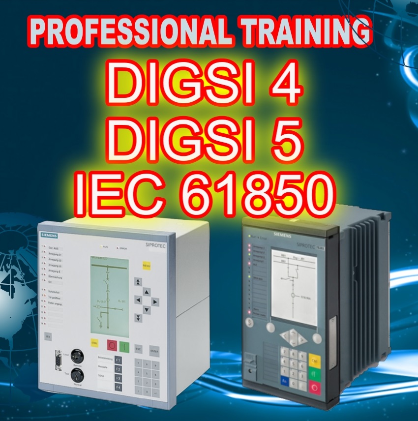
In this package, you get Trained DIGSI 4 and DIGSI 5 to work with SIPROTEC 4 & 5, how to work with Etap software, and how to use IEC 61850 for integration and communication between different equipment brands.

Product detail:

IEC 61850 training package (4 hrs – 1.5 GB)
SIPROTEC 4 and DIGSI 5 training package (7 hrs – 1.8 GB)
SIPROTEC 4 and DIGSI 4 Training package ( 3hrs – 830 MB)
ETAP for protection engineers (5.5 hrs)
  • DIGSI 5 Training: 435 Minutes – Full HD Size ( 1.9 GB), In English, By Dr. Saeed Roostaee
  • DIGSI 4 Video Training: 185 Minutes, In English, By Dr. Saeed Roostaee
  • IEC 61850 configuration Video Training: 4 hrs Language, In English, By Dr. Saeed Roostaee
  • ETAP Video Training: 5.5 hrs, In English
This package is a combination of IEC 61850, DIGSI 4, and DIGSI 5 courses. You can learn how to config SIPROTECT 4, and SIPROTECT 5, and IEC 61850. The material of each course is designed to help you and the training items are as follows:     

Product Detail:


SIPROTEC 4 and DIGSI 4 Training package (3hrs )
IEC 61850 Configuration (4 hrs )
SIPROTEC 5 and DIGSI 5 training package (7 hrs)

NAME length
Part 1: Substation Automation – an overview  05:39
Part 2: An introduction to IEC 61850 & how to learn it effectively 08:52
Part 3: Overview of the main features of IEC 61850 – Part I 08:58
Part 4: Overview of the main features of IEC 61850 – Part II 05:41
Part 5: IEC 61850 data structure and data format – Part I 33:34
Part 6: IEC 61850 data structure and data format – Part II 11:37
Part 7: IEC 61850 station in DIGSI 5 and IEC 61850 System Configurator 17:33
Part 8: GOOSE configuration and the publisher/subscriber LNs 14:34
Part 9: GOOSE simulation via IEDScout 06:31
Part 10: GOOSE configuration and simulation between SIP 5 & SEL relays 13:05
Part 11: Time synchronization settings and SNTP configuration 10:36
Part 12: Case study – Part I 14:56
Part 13: Case study – Part II 29:09
Part 14: Case study – Part III 23:41
Part 15: IEC 61850 configuration in DIGSI 4 20:03
Part 16: IEC 61850 configuration between SIP 4 & SIP 5 12:36
Part 17: Sample project 08:56

IEC 61850 Configuration (4 hrs-1.5 GB)

NAME length
Part 1: How to install DIGSI 4 01:57
PART 2: Introduction to SIPROTEC Relay families 06:50
Part 3: wiring connection 03:02
Part 4: start with DIGSI 19:12
part 5: Archive, import, export 12:36
Part 6: Masking I/O 11:00
Part 7: Masking I/O 04:51
Part 8: Masking I/O 13:08
Part 9: Default and Control Display 16:21
Part 10: CFC 11:57
Part 11: CFC and Implementation of experimental example 07:59
Part 12: CFC Interlocking Example 04:26
Part 13: CFC Protection Example 04:13
Part 14: CFC Explanation of all blocks 11:01
Part 15: Power system data 1 08:34
Part 16: Setting Group 19:13
Part 17: Oscillographic Fault Recorders 03:06
Part 18: General Device Settings 04:39
Part 19: Time Synchronization and Interfaces 03:40
Part 20: Device Driver and Firmware Update 09:04
Part 21: Config SIPROTEC relay in a Practical Project 14:36

DIGSI 5 Online Training

NAME length
part 1: SIPROTEC 5 relay families and applications 08:42
part 2: The online SIPROTEC 5 configurator 24:20
part 3: DIGSI 5 installation 04:27
part 4: DIGSI 5 upgrade and import device drivers 07:36
part 5: DIGSI 5 Vs DIGSI 4 16:05
Part 6:User interface and general setting 14:24
part 7: Case study relay configuration- part 1 16:57
part 8: SIPROTEC 5 Offline configuration I 15:31
part 9: Import specific communication drivers & inconsistencies 05:28
part 10: case study relay configuration- part 2 18:05
part 11: Distance relay configuration I 09:45
part 12: Distance relay configuration II 15:50
part 13: Distance relay configuration III 07:13
part 14: Function in DIGSI 5 16:07
part 15: case study relay configuration- part 3 12:40
part 16: case study relay configuration- part 4 05:48
part 17: case study relay configuration- part 5 15:57
part 18: case study relay configuration- part 6 17:45
part 19: Display Page configuration 15:38
part 20: case study relay configuration- part 7 10:06
part 21: CFC Configuration 09:08
part 22: CFC Analysis 06:13
part 23: CFC in DIGSI 5 and DIGSI 4 08:33
part 24: case study relay configuration- part 8 07:06
part 25: Case study busbar configuration- part 1 12:53
part 26: Case study busbar configuration- part 2 16:05
part 27: Case study busbar configuration- part 3 17:14
part 28: Case study busbar configuration- part 4 10:31
part 29: Case study busbar configuration- part 5 12:29
part 30: Case study busbar configuration- part 6 15:12
part 31: Case study busbar configuration- part 7 12:23
part 32: Case study busbar configuration- part 8 11:20
part 33: Case study busbar configuration- part 9 10:06
part 34: Case study busbar configuration- part 10 09:48
part 35: Case study busbar configuration- part 11 09:30

SIPROTEC 5 and DIGSI 5 training package

DIGSI 4 offline video training package:
Total length: 185 Minutes
Language: English
Trainer: Dr. Saeed Roostaee

DIGSI 5 offline video training package:
Total length: 435 Minutes
Language: English
Trainer: Dr. Saeed Roostaee

IEC 61850 System Configurator offline video training package:
Total length: 246 Minutes (4 hours)
Language: English
Trainer: Dr. Saeed Roostaee

+ Free and fast technical support +Free certificate for each course + Continuous update

Download:

Contact me WhatsApp: +989129613659

saeed61850@gmail.com/

DIGSI4 training using examples. we will be taking you through all the key stages of working with DIGSI 4. Among other things, we will be showing you how to Create station topology, parameterize control monitor devices, Route information, Change display images, Configure logical functions, Task definition, Topology, Parameters, Routing, Logics, Display, Configuring busbar protection, Exchanging, and archiving data, Analyzing faults with SIGRA 4, Working online, Modem Connection, Direct Connections, Ethernet and IEC 61850         

Training on DIGSI 4 and DIGSI 5 Training, contact us 

Rs 2500 Click here to pay on

DIGSI 5 Training
DIGSI 4 Training Full package

leave a comment on this post or Contact us for details

  • Installing DIGSI 4
  • Managing Projects
  • Working with the Devices
  • Optimizing Parameterization

Sample page of the file:

The first step is to create a new project. The DIGSI Manager has been started, a project dialog box has not yet been opened.

Click File- New of the menu bar, enter a new project name and confirm with OK.

The project dialog box is displayed.

Names and symbols of all project containers are displayed in a hierarchical tree structure. To put it less complicated, we could say that containers are displayed. This pane is called a tree view. An opened folder is the first symbol to be displayed in this pane. The opened folder is designated as project 1 and represents the top level, the project itself.

The right pane of the window shows a folder-type object. If the DIGSI 4 Remote program is installed, a phone book type object and modem type object each are displayed in addition. Otherwise, this pane of the window continues to remain empty. This page serves to display further names of symbols of objects, which are contained in one of the selected containers of the tree view. To put it less complicated, we could say that this pane shows objects. Since the right pane of the window is represented as a list, this structure is called a list view.

Up to four objects are first automatically created within a new project of the tree view.
Project (cannot be inserted manually)
Folder (to structure a project)
Phone Book (station addresses for a modem connection)
Modem (for the communication  SIPROTEC between your computer and the SIPROTEC 4 device
modem connection for the storage of modem profiles).
Phone Book and modem will be created automatically if the DIGSI 4 Remote component has been loaded.

The SIPROTEC 4 device object type represents a real SIPROTEC 4 device with all its setting values and process data.

The V3/V2 device object type serves to create shortcuts linked to the V3/V2 devices within the project structure. These device data are processed with DIGSI-V3.x.

The SIPOROTEC 4 version object type is created to document different parameter settings groups of a SIPROTEC 4 device. The device address (VD number) of the corresponding versions is identical to that of the original device.

The left window pane contains the names and symbols of all project containers in a hierarchical tree structure.
The right window pane displays the objects of the selected folders. The structure is designated as a list view.

Your first step to creating a system-specific project structure is to insert folder-type blank containers in the corresponding levels.

Click a folder object to insert a subordinate folder via the menu command ® Paste. A maximum of 9 levels is the permissible hierarchy depth.

Several objects can be juxtaposed in parallel.

The names of the folders can be renamed to easily adjust to the requirements of your operation.

As a first step, you create a new project. The DIGSI 4 Manager is started, no project window is open.

  • Click File ® New in the menu bar.
  • In the New dialog box, enter Project 1 as a name for the new project.
    Don‘t modify any other settings.
  • Click OK.
    The project window is now displayed in the working range. Put it to full size.
  • An object of the type Hierarchical level is inserted automatically upon creating a new project.
  • Click this object and then click the selected name. Enter Region Nord as a new name.
  • Right-click an existing hierarchical level and insert the lower-level hierarchical level via the context menu Insert new object ® Hierarchical level. Enter the new name.
  • Click a hierarchical level, e.g. Feeder 1, and open the device catalog via the context menu.
  • Select the device and draw it on the hierarchical level.

The Device Catalog shows all SIPROTEC 4 devices available (installed) in the DIGSI 4 Manager.
The device catalog is an independent item. When you open the catalog, a button is created in the taskbar by Windows. The device catalog can remain open while working with the DIGSI 4 Manager to install all required SIPROTEC 4 devices.

Select a folder type object and click View ® Device Catalog to open the Device Catalog window.

The device catalog has a structure. Clicking a plus sign or double-clicking a folder icon will open the subordinate level.

For example, if you double-click 7SJ (time overcurrent protection), all installed SIPROTEC 4 devices with the device type names and the variant numbers will be displayed.

Short technical information is displayed on the lower catalog border for each device selected.

Note: Devices cannot be placed directly underneath the project folder!

The MLFB tab serves to determine the order number of the selected SIPROTEC 4 device in DIGSI 4. The order number is the code for the type and variant of the SIPROTEC 4 device. The order number is called the MLFB number.
Order number determination in DIGSI 4 affects all further parameterization options. Identical MLFB numbers are necessary for the communication between the DIGSI 4 device operation and the connected SIPROTEC 4 device. This is checked when setting up the connection.

The MLFB tab contains several drop-down list boxes. The drop-down list boxes related to the selected SIPROTEC 4 device are activated, only. These drop-down list boxes serve to select the order numbers to define the SIPROTEC 4 design and type in DIGSI 4.

As a first step, create a new project. The DIGSI 4 Manager is started, no project window is open.

Click File ® New in the menu bar.

  • In the New dialog box, enter Project 1 as a new project name.
    Don‘t change any other settings.
  • Click OK.
    The project window is now displayed in the working range. Put it to full size.

When creating a new project, an object of the type Hierarchical level is inserted automatically.

  • Click this object and then click the selected name. Enter Region North as a new name.
  • Right-click on an existing hierarchical level and insert a lower hierarchical level vie the context menu Insert new object ® Hierarchical level. Enter the new name.
  • Click a hierarchical level, e.g. Feeder 1, and open the device catalog via the context menu.
  • Select the device and draw it on the hierarchical level.
  • As a first step, create a new project. The DIGSI 4 Manager is started, no project window is open. Click File ® New in the menu bar.
    • In the New dialog box, enter Project 1 as a new project name.
      Don‘t change any other settings.
    • Click OK.
      The project window is now displayed in the working range. Put it to full size.

    When creating a new project, an object of the type Hierarchical level is inserted automatically.

    • Click this object and then click the selected name. Enter Region North as a new name.
    • Right-click on an existing hierarchical level and insert a lower hierarchical level vie the context menu Insert new object ® Hierarchical level. Enter the new name.
    • Click a hierarchical level, e.g. Feeder 1, and open the device catalog via the context menu.
    • Select the device and draw it on the hierarchical level.

Properties like object name, comment, or date of creation, have been assigned to all objects (General tab).
Some properties only refer to certain objects, for ex. the MLFB number for the SIPROTEC 4 devices or the device communication settings.
The values of the majority of the properties can be changed.

Select the object and click the View ® Details menu item to display the object properties. You can also open the Object Properties dialog box via the context menu or via the menu item Edit ® Object Properties

If the property values are grayed, they cannot be changed. Depending on the entries you made in other text boxes, such text boxes may be activated. Property values in white/empty text boxes can be edited.

DIGSI 4 training pack