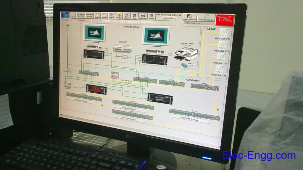
Substation Automation Functions (Control Authority, Bay Blocking, Telecontrol Blocking, Time Synchronization, Fault Recording, Redundancy)
SICAM PAS in Star Configuration
SICAM PAS in (Fiber Optic) Ring
SICAM PAS FO Station LAN
SICAM PAS Installation
Licensing
Licensing With Feature Enabler
SICAM PAS Basic packet and options
SICAM PAS Configuration User Administration Tool
IEC 61850 Services in IEDs and SICAM PAS
SICAM PAS Configuration (Working with Project Databases, Creating a New Database, Adding and Managing Systems, Adding an Application (IEC 61850 Client), Importing a SCD file, Updating One or Several Device(s), Adding ModbusApplication, Parameterizing ModbusApplication, Added EMA90 ModbusMap, Defining the Device Template (ModbusMap), Adding IEC 60870-5-101 Slave Application, Inserting the Control Center of IEC 60870-5-101 Slave, Inserting the SNMP Application, Monitoring IEC 61850 IEDs Connection Status With SNMP, Inserting a PASCC Application to Full Server System, Inserting Control Center to PASCC Application, Inserting a PASCC to a New System (DIP)
Creating a Full Server Computer
Creating an IEC101-Master to connect the RTU
Importing the RTU file
Communication IEC 60870-5-103
Communication OPC-Client (based on COM/DCOM)
Communication OPC-XML-Server
SICAM PAS Configuration (Topology Management, Filtering, Topology Tree Structure, Selection of Signals for Each Sub-Level, Modbus (Measuring) Signals
SICAM PAS Configuration (Automation (Soft PLC), Logic Processing with CFC, Info to / Com from SoftPLC (Mapping), Creating New CFC Program, Connection of Source and Destination Variables
Routing messages from/to SoftPLC
Renaming duplicated message
Creating a CFC file
CFC block
Inserting Variable into interconnection column
Grouping with a “PAS_GROUPI”-Function Block
Converting a Counter Differential Value to a Counter Final Value
Interlocking
Run Sequence
Online Mode
Watchlist
CDA (Control Data Analyzer) Necessary settings
Mapping an output to CDA
Human-Machine Control Center Mapping, Exporting of HMI1 Interface
How to select a group of messages
Normalization
Create a Normalization Template
Scaling a measured value
Normalization as a multiple-used template
Assignment of normalization in Mapping
Adaptation of transformer tap position indications
substation protection and control systems development, from conventional to digital substations with some pictures of a real substation. Then, it presents the importance of communication in this system and why it is necessary to use a common communication protocol and molding function system in the substation automation system.
Part 2: An introduction to IEC 61850 & how to learn it effectively
A brief history of the standard IEC 61850 Ed.1 & Ed.2, its purpose, and its benefits are presented in this chapter. One problem with learning the IEC 61850 is the variety of documents, topics, and the gap between academics and industry in this area. This part introduces an effective way to learn practical IEC 61850 standards.
Part 3: Overview of the main features of IEC 61850-Part I
This part overviews the OSI model, MMS protocol, and the used devices in the IEC 61850 network. Then, different packets (GOOSE, Report, and Sample Value) and services (for time synchronization, master-slave, client/server, and publisher/subscriber) are presented in this module.
Part 4: Overview of the main features of IEC 61850-Part II
The concept of object-oriented modeling and the data modeling of IEC 61850 are presented in this part. Then different types of GOOSE messages, report control blocks, and SCL files are introduced. This part also presents the connection terminals, communication, and time synchronization ports of a merging unit installed in the process bus lab setup.
Part 5: IEC 61850 data structure and data format-Part I
Initial IEC 61850 settings in DIGSI 5 and the connection between the information routing matrix and IEC 61850 structure editor are presented in this part. The device is opened via OMICRON IEDScout and the data structure of the IED and the relation between them and the IEC 61850 signals in DIGSI 5 are explained. Then the device is exported with different IEC 61850 data formats and different sections of the exported files are explained in detail. To understand the interoperability of IEC 61850, a device from another manufacturer (SEL) is also exported and different sections of this file are explained.
Part 6: IEC 61850 data structure and data format-Part II
Different tools of the IEC 61850 structure editor in DIGSI 5. Editing of the IEC 61850 data model and adding the user-defined LNs are explained too.
Part 7: IEC 61850 station in DIGSI 5 and IEC 61850 System Configurator
A device is added to the IEC station in DIGSI 5 and the station is opened via IEC 61850 System Configurator to explain different parts of the station and the configurator. The connection between each editor in the configurator and the station file is also presented in this part.
Part 8: GOOSE configuration and the publisher/subscriber LNs
The GOOSE configuration between two SIPROTEC 5 devices is presented in this part. The publisher and the subscriber Logical Nodes before the GOOSE configuration and after the GOOSE configuration are compared in the IEC 61850 station files and the information matrix in DIGSI 5.
Part 9: GOOSE simulation via IEDScout
The publisher and subscriber IEDs before and after GOOSE configuration are simulated in the OMICRON IEDScout. The sniffer tool is used to capture the simulated GOOSE of the publisher IED. To show the GOOSE repetition, the value of the GOOSE signal is changed in the IED simulator, and the captured GOOSE after the change is analyzed too.
Part 10: GOOSE configuration and simulation between SIP 5 & SEL relays
An IED from another manufacturer (SEL) is added to the station and the GOOSE configuration between SEL and SIPROTEC IEDs is presented in the IEC 61850 configurator. Then the simulation of the publisher and subscriber IEDs has been done via IEDScout.
Part 11: Time synchronization settings and SNTP configuration
The configuration of the SNTP (Simple Network time protocol) for time synchronization in DIGSI 5 and IEC 61850 system configurator
Part 12: Case study-Part I
In DIGSI 5 training, relays were added and configured based on the diagram of the case study project. This part presents the IEC 61850 configuration in the same case study project. The IEC 61850 and SNTP settings have been entered based on the case study project documents. The table of the communication cables and the diagram of the substation automation architecture is described in this part.
Part 13: Case study-Part II
The report configurations based on the table of reports configured on servers are presented in this part. The signals of the distance IED are added to the data set and a report control block is added to transmit the event to the clients. The report control block settings are also explained in this part.
Part 14: Case study-Part III
The GOOSE configurations are based on the GOOSEs table and the GOOSE message subscription list.
Part 15: IEC 61850 configuration in DIGSI 4
the IEC 61850 configuration in DIGSI 4
The data model of a SIPROTEC 4 IED is shown in the OMICRON IEDScout
the IEC 61850 signals in the masking IO with this data model
Part 16: IEC 61850 configuration between SIP 4 & SIP 5
The IEC 61850 station configuration with SIPROTEC 4 and SIPROTEC 5 devices
Part 17: Sample project
The application of GOOSE signals, a sample project
The IEDs and IEC 61850 configurations (send a GOOSE signal from SIPROTEC 5 to SIPROTEC 4)
Use the GOOSE signal in a function block of the DIGSI 4 CFC editor
IEC 61850 configuration in PCM600 (Process bus and Goose configuration) IEC 61850 Engineering with PCM600 How to configure IEC 61850 with Easergy Studio How to configure IEC 61850 for ACE850 module (CET850) How to configure IEC 61850 for SEL relays
Click here to see the certificates of the participants
IP communication is being extensively introduced into the operation of the Electrical Power Utility. The substation IP network environment has evolved from acting as an extension of the office LAN to a state, where it is carrying multiple services, including the transport of critical and sensitive data. IP communication, being a one-platform solution that relieves you from designing and maintaining more than one network, is not a one-technology solution. Therefore, the implementation of an IP network needs to be carefully planned to achieve the expected scalability and performance. This Technical Brochure includes the following:
A compilation of user requirements and expectations concerning existing and envisaged services in the new
networked environment of the substation.
A description of possible network migration processes
Guidelines on how to choose an optimum network architecture
A description of important parameters to be considered for each relevant technology.
Six case studies describing project and process experiences
This course is an overview of the application, properties, and functional scope of the 6MD bay controller. Also, the configuration and parameters of the 6MD IED are presented in this training.