
SIEMENS Products

  • Online+ Pre-recorded Training
  • 3-5 April 2024
  • 22-24 March 2024
  • Pre-requisite training: DIGSI 4, DIGSI 5, IEC61850
  • Language: English
  • Supporting Files
  • Trainer: Dr. Saeed Roostaee (Profile)
  • Limited seats available
  • Registration link: expired

Module I: Substation Automation System

  • Substation Automation System-an overview
  • Introduction to Communication
  • Network Theory
  • Fundamentals of Communication Via Ethernet Various Topologies in SIEMENS SAS

Module II: Bay Level Engineering (IEC 61850 and Modbus)

  • Add SIPROTEC 4 6MD66 device
  • Setting the Network Parameters
  • 6MD configuration
  • IEC61850 Configuration
  • Updating ICD – Files

Module III: Station Level Engineering SICAM PAS

  • Introduction to SICAM PAS Automation System
  • SICAM PAS Tasks
  • Fields of Application
  • SICAM PAS Features
  • Scalability – Software and Hardware Configuration for Small to Large Applications
  • Basic Package “ Full Server”
  • SICAM PAS Packages (IEC 61850, Profibus FMS (SICAM/SIPROTEC specified protocols), IEC 60870-5-103, DNP V3.00, Profibus DP, Modbus, ILSA (Internal LSA protocol, OPC-Client, Automation CFC)
  • Licensing
  • Licensing With Feature Enabler
  • IEC 61850 Services in IEDs and SICAM PAS
  • SICAM PAS Configuration (Working with Project Databases, Creating a New Database, Adding and Managing Systems, Adding an Application (IEC 61850 Client), Importing a SCD file, Updating One or Several Device(s), Adding ModbusApplication, Parameterizing ModbusApplication, Added EMA90 ModbusMap, Defining the Device Template (ModbusMap), Adding IEC 60870-5-101 Slave Application, Inserting the Control Center of IEC 60870-5-101 Slave, Inserting the SNMP Application, Monitoring IEC 61850 IEDs Connection Status With SNMP, Inserting a PASCC Application to Full Server System, Inserting Control Center to PASCC Application, Inserting a PASCC to a New System (DIP)
  • Creating a CFC file
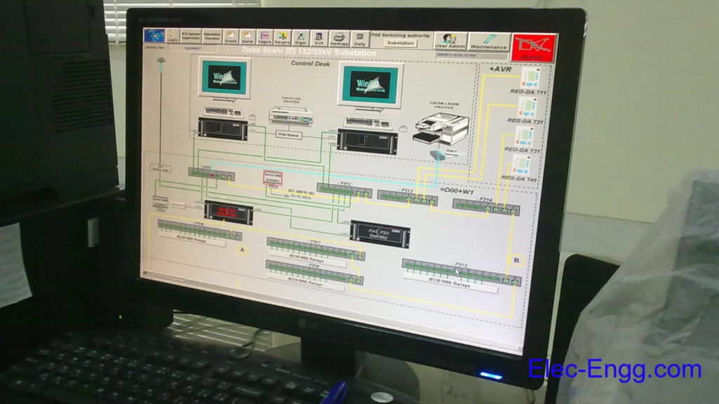
  • Human-Machine Control Center Mapping, Exporting of HMI1 Interface
  • Normalization
  • Create a Normalization Template
  • Scaling a measured value
  • Assignment of normalization in Mapping
  • Archiving Configured Project, Un-archiving Project
  • SICAM PAS Value Viewer
  • Control function
  • Testing data
  • ValueViewer: Communication diagnostics

Module IV: SICAM SCC

  • Export of HMI information from SICAM PAS
  • Check the content of a PXD file
  • Introduction to SICAM PASCC Control Center
  • SICAM PASCC Control Center ‐ Overview
  • SIMATIC WinCC
  • SICAM PASCC Components
  • SICAM PASCC Communication
  • SICAM PAS Wizard
  • WinCC Explorer
  • Graphic Objects Library
  • Switchgear Objects
  • Schwitchgear Objects – Styles and States
  • Alarm Logging – Message List
  • Control & Monitoring
  • WinCC & PASCC Licensing
  • SIMATIC WinCC / SICAM PASCC Installation Steps
  • Transfer The License Keys
  • SIMATIC WinCC / SICAM PASCC Time Synchronization & NTP
  • SICAM PASCC Starting The WinCC/PASCC Software
  • SICAM PASCC Creating/ Opening a New Project
  • SICAM PASCC Defining The Computer Properties General Tab, Startup Tab, Parameters Tab, Graphics Runtime Tab
  • Adding a Communication Driver
  • Connection Properties
  • Entering the IP Address of SICAM PAS Servers
  • Error Log File of SICAM PAS Wizard
  • Select the Right SICAM PAS Protocol Suite
  • Set PAS IP Connection
  • Importing of the Sample Pilot Project .pxd File
  • Checking Structure Tags of a New Project
  • Structure Tag Elements
  • Symbol Library
  • SICAM Administrative Internal Tags
  • Schwitchgear Objects – Tag Connection
  • Design of Graphical Objects
  • Switchgear Objects – Sychro-Check
  • Alarm Logging – Events & Alarms
  • Alarm Logging – Message Queue & Mes Ack Tags
  • Tag Logging – Measured Values
  • WinCC Horn Tools– Sound File
  • Tag Logging – Archive Configuration
  • Trends Picture
  • Topological coloring
  • Event List
  • Alarm List
  • Protection Message List
  • Horn, Alarm Acknowledgment
  • Creating an Event List in the Graphics Designer
  • User Administrator
  • Login via button
  • Report Designer – Print Job
  • Project Archive, Duplicator
  • Bay Blocking

SIPROTEC 5 & DIGSI 5 Training Course

  • Video-based (pre-recorded)
  • Trainer: Dr. Saeed Roostaee (Profile)
  • Course creation: Nov 2018
  • Last update: 9 September 2023
  • Total Time till July 2023: 9 hrs and 25 min
  • + Auxiliary Files
  • + Certificate of completion
  • + Technical Support

DIGSI 5 Training updateLength
Update 01: SIPROTEC 5 Hardware, Front panel20:47
Update 02: SIPROTEC 5 Hardware- Expansion modules23:47
Update 03: SIPROTEC 5 Applications13:02
Update 04: DIGSI 5 optimal installation, DIGSI 5 Upgrade19:23
Update 05: DIGSI 5 General Settings04:01
Update 06: DIGSI 5 user interface 04:55
Update 07: SIPROTEC 5 Offline Configuration11:12
Update 08: SIPROTEC 5 Online Configuration07:17
Update 09: SIPROTEC 5 and SIPROTEC 5 compact online configuration19:16
Update 10: SIPROTEC 5 Web User Interface 16:45
Update time till July 2023:2.5 hrs

DIGSI 5 Training list:

NAMELength
Part 01: SIPROTEC 5 relay families and applications08:42
Part 2: The online SIPROTEC 5 configurator24:20
Part 3: DIGSI 5 installation04:27
Part 4: DIGSI 5 upgrade and import device drivers07:36
Part 5: DIGSI 5 Vs DIGSI 416:05
Part 6:User interface and general setting14:24
Part 7: Case study relay configuration- part 116:57
Part 8: SIPROTEC 5 Offline Configuration 15:31
Part 9: Import specific communication drivers & inconsistencies05:28
Part 10: case study relay configuration- part 218:05
Part 11: Distance relay configuration I09:45
Part 12: Distance relay configuration II15:50
Part 13: Distance relay configuration III07:13
Part 14: Function in DIGSI 516:07
Part 15: case study relay configuration- part 312:40
Part 16: case study relay configuration- part 405:48
Part 17: case study relay configuration- part 515:57
Part 18: case study relay configuration- part 617:45
Part 19: Display Page configuration15:38
Part 20: case study relay configuration- part 710:06
Part 21: CFC Configuration09:08
Part 22: CFC Analysis06:13
Part 23: CFC in DIGSI 5 and DIGSI 408:33
Part 24: case study relay configuration- part 807:06
Part 25: Case study busbar configuration- part 112:53
Part 26: Case study busbar configuration- part 216:05
Part 27: Case study busbar configuration- part 317:14
Part 28: Case study busbar configuration- part 410:31
Part 29: Case study busbar configuration- part 512:29
Part 30: Case study busbar configuration- part 615:12
Part 31: Case study busbar configuration- part 712:23
Part 32: Case study busbar configuration- part 811:20
Part 33: Case study busbar configuration- part 910:06
Part 34: Case study busbar configuration- part 1009:48
Part 35: Case study busbar configuration- part 1109:30
Total Time7 hrs

Demo

send a request to saeed61850@gmail.com

why DIGSI 5 Training Pack?

  • you have lifetime access to the files.
  • you can start your learning from wherever you are.
  • You can save time and money.
  • you get a certificate of completion. 
  • you can get free updates automatically.

Learning SIPROTEC 5 & DIGSI 5 with ease

Learning DIGSI 5 and SIPROTEC 5 relays becomes easier and more effective when the course is updated continuously and you can learn it anywhere. This course is pre-recorded, and all updates will be added for free.

DIGSI 5 Training Package:

Update 10: SIPROTEC 5 Web User Interface

SIPROTEC 5 and DIGSI 5 training package

Click here to download the Professional package (DIGSI4, DIGSI5, IEC61850)

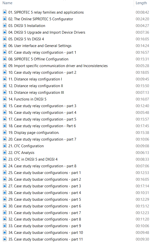
SIPROTEC 5 relay families and applications; How to install, transfer License and upgrade DIGSI 5; Import DIGSI 5, Device Drivers and Start with DIGSI 5
DIGSI 4 VS DIGSI 5 and DIGSI 5 Overview; Online and Offline SIPROTEC 5 Configurator; Functional Scope and Function Points; Working with Libraries and Elements; Managing Projects and Devices in Projects
Single-Line Configuration; Signals; Information Routing; Routing Measuring Points; Function Charts (CFC); Display Page; Advantages and Disadvantages of SIPROTEC 5 and DIGSI 5; Case study project; Configure SIPROTEC 5 Devices based on diagrams.

In this course, you will learn how to use and configure the IEC 61850 station

IEC 61850 Configuration Video Training

  • IEC 61850 Configuration
  • Language: English
  • Course creation: December 2018
  • Last update: September 2023
  • Total Time till September 2023: 5 hrs
  • + Auxiliary Files
  • + Certificate of completion
  • Trainer: Dr. Saeed Roostaee (Profile)

Main Course

  • Part 1 Substation Automation – An overview.
  • Part 2 An introduction to IEC 61850 & how to learn it effectively.
  • Part 3 Overview of the main features of IEC 61850.
  • Part 4 Overview of the main features of IEC 61850 – Part II
  • Part 5 IEC 61850 data structure and data format – Part I
  • Part 6 IEC 61850 data structure and data format – Part II
  • Part 7 IEC 61850 station in DIGSI 5 and IEC 61850 System Configurator.
  • Part 8 GOOSE configuration and the publisher-subscriber LNs.
  • Part 9 GOOSE simulation via IEDScout.
  • Part 10 GOOSE configuration and simulation between SIP 5 & SEL relays.
  • Part 11 Time synchronization settings and SNTP configuration.
  • Part 12 Case Study – Part I
  • Part 13 Case study – Part II
  • Part 14 Case study – Part III
  • Part 15 IEC 61850 configuration in DIGSI 4
  • Part 16 IEC 61850 configuration between SIP 4 & SIP 5.
  • Part 17 Sample project.

Updates and Supplementary Files

  • IEC 61850 configuration in PCM600 (Process bus and Goose configuration).
  • IEC 61850 Engineering with PCM600.
  • How to configure IEC 61850 with Easergy Studio
  • How to configure IEC 61850 for the ACE850 module (CET850).
  • How to configure IEC 61850 for SEL relays.

Helpful Files:

IEC protocols for substation communications

IEC 61850 Technical Overview

Download the IEC 61850 training package

Details Course

Part 1: Substation Automation- Overview

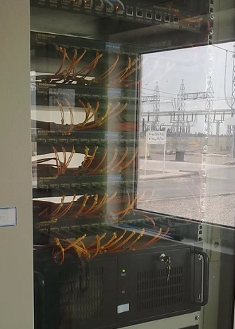
substation protection and control systems development, from conventional to digital substations with some pictures of a real substation. Then, it presents the importance of communication in this system and why it is necessary to use a common communication protocol and molding function system in the substation automation system.    

Part 2: An introduction to IEC 61850 & how to learn it effectively

A brief history of the standard IEC 61850 Ed.1 & Ed.2, its purpose, and its benefits are presented in this chapter. One problem with learning the IEC 61850 is the variety of documents, topics, and the gap between academics and industry in this area. This part introduces an effective way to learn practical IEC 61850 standards.

Part 3: Overview of the main features of IEC 61850-Part I

This part overviews the OSI model, MMS protocol, and the used devices in the IEC 61850 network. Then, different packets (GOOSE, Report, and Sample Value) and services (for time synchronization, master-slave, client/server, and publisher/subscriber) are presented in this module.

Part 4: Overview of the main features of IEC 61850-Part II

The concept of object-oriented modeling and the data modeling of IEC 61850 are presented in this part. Then different types of GOOSE messages, report control blocks, and SCL files are introduced. This part also presents the connection terminals, communication, and time synchronization ports of a merging unit installed in the process bus lab setup.

Part 5: IEC 61850 data structure and data format-Part I

Initial IEC 61850 settings in DIGSI 5 and the connection between the information routing matrix and IEC 61850 structure editor are presented in this part. The device is opened via OMICRON IEDScout and the data structure of the IED and the relation between them and the IEC 61850 signals in DIGSI 5 are explained. Then the device is exported with different IEC 61850 data formats and different sections of the exported files are explained in detail. To understand the interoperability of IEC 61850, a device from another manufacturer (SEL) is also exported and different sections of this file are explained.

Part 6: IEC 61850 data structure and data format-Part II

Different tools of the IEC 61850 structure editor in DIGSI 5. Editing of the IEC 61850 data model and adding the user-defined LNs are explained too.

Part 7: IEC 61850 station in DIGSI 5 and IEC 61850 System Configurator

A device is added to the IEC station in DIGSI 5 and the station is opened via IEC 61850 System Configurator to explain different parts of the station and the configurator. The connection between each editor in the configurator and the station file is also presented in this part.

Part 8: GOOSE configuration and the publisher/subscriber LNs

The GOOSE configuration between two SIPROTEC 5 devices is presented in this part. The publisher and the subscriber Logical Nodes before the GOOSE configuration and after the GOOSE configuration are compared in the IEC 61850 station files and the information matrix in DIGSI 5.

Part 9: GOOSE simulation via IEDScout

The publisher and subscriber IEDs before and after GOOSE configuration are simulated in the OMICRON IEDScout. The sniffer tool is used to capture the simulated GOOSE of the publisher IED. To show the GOOSE repetition, the value of the GOOSE signal is changed in the IED simulator, and the captured GOOSE after the change is analyzed too.

Part 10: GOOSE configuration and simulation between SIP 5 & SEL relays

An IED from another manufacturer (SEL) is added to the station and the GOOSE configuration between SEL and SIPROTEC IEDs is presented in the IEC 61850 configurator. Then the simulation of the publisher and subscriber IEDs has been done via IEDScout.

Part 11: Time synchronization settings and SNTP configuration

The configuration of the SNTP (Simple Network time protocol) for time synchronization in DIGSI 5 and IEC 61850 system configurator

Part 12: Case study-Part I

In DIGSI 5 training, relays were added and configured based on the diagram of the case study project. This part presents the IEC 61850 configuration in the same case study project. The IEC 61850 and SNTP settings have been entered based on the case study project documents. The table of the communication cables and the diagram of the substation automation architecture is described in this part.

Part 13: Case study-Part II

The report configurations based on the table of reports configured on servers are presented in this part. The signals of the distance IED are added to the data set and a report control block is added to transmit the event to the clients. The report control block settings are also explained in this part.

Part 14: Case study-Part III

The GOOSE configurations are based on the GOOSEs table and the GOOSE message subscription list.

Part 15: IEC 61850 configuration in DIGSI 4

  • the IEC 61850 configuration in DIGSI 4
  • The data model of a SIPROTEC 4 IED is shown in the OMICRON IEDScout
  • the IEC 61850 signals in the masking IO with this data model

Part 16: IEC 61850 configuration between SIP 4 & SIP 5

  • The IEC 61850 station configuration with SIPROTEC 4 and SIPROTEC 5 devices

Part 17: Sample project

  • The application of GOOSE signals, a sample project
  • The IEDs and IEC 61850 configurations (send a GOOSE signal from SIPROTEC 5 to SIPROTEC 4)
  • Use the GOOSE signal in a function block of the DIGSI 4 CFC editor

IEC 61850 configuration in PCM600 (Process bus and Goose configuration)
IEC 61850 Engineering with PCM600
How to configure IEC 61850 with Easergy Studio
How to configure IEC 61850 for ACE850 module (CET850)
How to configure IEC 61850 for SEL relays

Click here to see the certificates of the participants

IEC 61850 System Configurator Video Training

Auxiliary files:

Related training packages:

Information

  • Course Name: SIPROTEC 5 and DIGSI 5 (advanced)
  • Trainer: Dr. Saeed Roostaee
  • Format: Pre-recorded videos (demo is available)
  • Course creation: June 2023
  • Last update: July 2023

Note: This course can also be held either Online or Face to face based on the request

Course Structure:

  • Module 1: SIPROTEC 5 Hardware and ordering
  • Module 2: Starting with DIGSI 5
  • Module 3: Working with SIPROTEC 5 in online mode
  • Module 4: System Functions
  • Module 5: Function Groups
  • Module 6: SIPROTEC 7SJ8
  • Module 7: SIPROTEC 7SA8
  • Module 8: SIPROTEC 7UT8
  • Module 9: SIPROTEC 7SS8
  • Module 10: SIPROTEC 7SK8
  • Module 11: SIPROTEC 7VK8
  • Module 12: SIPROTEC 7SD8
  • Module 13: SIPROTEC 7SL8
  • Module 14: SIPROTEC 7SX8
  • Module 15: SIPROTEC 7UM8
  • Module 16: SIPROTEC 7MD8
  • Module 17: Functions and Settings
  • Module 18: Signals and Masking IO
  • Module 19: CFC
  • Module 20: Control Functions
  • Module 21: Display Page configuration
  • Module 22: Functional Tests
  • Module 23: Measured Values
  • Module 24: Power Quality
  • Module 25: Supervision
  • Module 26: Communication
  • Module 27: IEC 61850
  • Module 28: Digital Twin
  • Module 29: Case Study 7UT8
  • Module 30: Case Study 7VK8
  • Module 31: Case Study 7SA8
  • Module 32: Case Study 7SS8

Course Details (Note: This part is continuously updating)

Module: SIPROTEC 5 Hardware and order

  • SIPROTEC5 Hardware
  • DIGSI 5 installation and DDD
  • General Settings
  • DIGSI 5 User interface
  • New project + Add device (Offline)
  • Modify the order code in the SIPROTEC online configurator
  • SIPROTEC 5 Online Configurator
  • Function Point
  • SIP 5 Configuration Procedure

Module: Online & Working with SIPROTEC 5

  • Connect to SIPROTEC 5
  • Indications
  • Fault Recording
  • Log
  • Reading Indications on the On-Site Operation Panel
  • Reading Indications from the PC with DIGSI 5
  • Displaying Indications
  • Operational Log
  • Fault Log
  • Switching-Device Log
  • Ground-Fault Log
  • Setting-History Log
  • User Log
  • Security Log
  • Device-Diagnosis Log
  • Communication Log
  • Communication-Supervision Log
  • Motor-Starting Log
  • Saving and Deleting the Logs
  • Spontaneous Indication Display in DIGSI 5
  • Spontaneous Fault Display on the On-Site Operation Panel
  • Stored Indications in the SIPROTEC 5 Device
  • Resetting Stored Indications of the Function Group
  • Test Mode and Influence of Indications on Substation Automation Technology
  • Changing the Transformation Ratios of the Transformer on the Device

Module: System Functions

  • Sampling-Frequency Tracking and Frequency Tracking Groups
  • Text Structure and Reference Number for Settings and Indications
  • Processing Quality Attributes
  • Protection Communication
  • Date and Time Synchronization
  • User-Defined Objects
  • Device Settings
  • Data Types
  • Function Control
  • Connection Examples
  • Chatter blocking
  • Settings-Group Switching

Module: Function Groups

  • Voltage current 3-Phase
  • Circuit-breaker
  • Process Monitor
  • Voltage-current 1-phase
  • Motor
  • Line
  • Voltage 3-Phase
  • Analog Units
  • User-Defined Function Group
  • Recording
  • Motor Monitor
  • Current-Flow Criterion
  • Circuit-Breaker Condition for the Motor
  • Closure Detection
  • Motor-State Detection
  • Cold-Load Pickup Detection
  • Thermal Replica Rotor
  • Capacitor Bank

Module: Functions and Settings

  • Power-System Data
  • Overcurrent Protection, Phases
  • Overcurrent Protection, Ground
  • Line Differential Protection
  • Stub Differential Protection
  • Restricted Ground-Fault Protection
  • Distance Protection with Reactance Method (RMD)
  • Distance Protection with Classic Method
  • Impedance Protection
  • Power-Swing Blocking
  • Teleprotection with Distance Protection
  • Universal Teleprotection with Distance Protection
  • Ground-Fault Protection for High-Resistance Ground Faults in Grounded Systems
  • Teleprotection with Ground-Fault Protection
  • Universal Teleprotection with Ground-Fault Protection
  • Echo and Tripping in the Event of Weak Infeed 874
  • Tripping with Missing or Weak Infeed According to French Specification
  • External Trip Initiation
  • Automatic Reclosing Function
  • Directional Overcurrent Protection, Phases
  • Positive-Sequence Overcurrent Protection
  • Instantaneous High-Current Tripping
  • Group Indications of Overcurrent Protection Functions
  • Overcurrent Protection, 1-Phase
  • Voltage-Dependent Overcurrent Protection, Phases
  • Sensitive Ground-Fault Detection
  • Non-Directional Intermittent Ground-Fault Protection
  • Directional Intermittent Ground-Fault Protection
  • Negative-Sequence Protection
  • Directional Negative-Sequence Protection with Current-Independent Time Delay
  • Undercurrent Protection
  • Overvoltage Protection with 3-Phase Voltage
  • Overvoltage Protection with Positive-Sequence Voltage
  • Overvoltage Protection with Negative-Sequence Voltage
  • Overvoltage Protection with Positive-Sequence Voltage and Compounding
  • Overvoltage Protection with Zero-Sequence Voltage/Residual Voltage
  • Overvoltage Protection with Any Voltage
  • Undervoltage Protection with 3-Phase Voltage
  • Undervoltage Protection with Positive-Sequence Voltage
  • Undervoltage Protection with Any Voltage
  • Rate-of-Voltage-Change Protection
  • Undervoltage-Controlled Reactive-Power Protection
  • Voltage-Comparison Supervision
  • Fault Locator
  • Fault Locator Plus
  • Over frequency Protection
  • Under frequency Protection
  • Rate of Frequency Change Protection
  • Under frequency Load Shedding
  • Phase-Sequence Switchover
  • Instantaneous Tripping at Switch onto Fault
  • Thermal Overload Protection, 3-Phase – Advanced
  • Thermal Overload Protection, 1-Phase
  • Temperature Supervision
  • Circuit-Breaker Failure Protection
  • Circuit-Breaker Restrike Protection
  • Out-of-Step Protection
  • Inrush-Current and 2nd Harmonic Detection
  • Power Protection (P, Q), 3-Phase
  • Current-Jump Detection
  • Voltage-Jump Detection
  • Vector-Jump Protection
  • Arc Protection
  • Voltage Measuring-Point Selection

Module: Specific Functions

  • Current-Unbalance Protection for Capacitors, 1-Phase
  • Peak Overvoltage Protection for Capacitors
  • Motor-Starting Time Supervision
  • Motor Restart Inhibit
  • Load-Jam Protection Motor
  • Thermal Overload Protection, Rotor

Module: Control Functions

  • Introduction
  • Switching Devices
  • Switching Sequences
  • Control Functionality
  • Synchronization Function
  • User-Defined Function Block [Control]
  • CFC-Chart Settings
  • Tap Changers
  • Voltage Controller
  • Point-on-Wave Switch

Module: Functional Tests

  • Direction Test of the Phase Quantities
  • Functional Test Protection Communication
  • Functional Test of the Line Differential Protection
  • Functional Test for Overvoltage Protection with Zero-Sequence Voltage/Displacement Voltage
  • Primary and Secondary Tests of the Circuit-Breaker Failure Protection
  • Circuit-Breaker Test
  • Out-of-Step Protection Function Test
  • Functional Test of the Inrush-Current Detection
  • Functional Test of the Trip-Circuit Supervision
  • Power-Swing Blocking Functional Test
  • Functional Test for the Phase-Rotation Reversal
  • Functional Test for Overvoltage Protection with Zero-Sequence Voltage/Residual Voltage
  • Directional Testing for Isolated or Resonant-Grounded Systems
  • Primary and Secondary Testing of the Synchronization Function
  • Commissioning Hints for Voltage Control

Module: Measured Values

  • Operational Measured Values
  • Fundamental and Symmetrical Components
  • THD and Harmonics
  • Minimum/Maximum Values
  • Average Values
  • Energy Values
  • Circuit-Breaker Monitoring
  • Statistical Values of the Primary System

Module: Power Quality

  • Voltage Variation
  • Voltage Unbalance
  • THD and Harmonics
  • Total Demand Distortion

Module: Supervision

  • Resource-Consumption Supervision
  • Supervision of the Secondary System
  • Supervision of the Device Hardware
  • Supervision of Device Firmware
  • Supervision of Hardware Configuration
  • Supervision of Communication Connections
  • Error Responses and Corrective Measures
  • Group Indications

Module: IEC 61850

  • External Signals
  • Quality Processing/Affected by the User for Received GOOSE Values
  • Quality Processing/Affected by the User in CFC Charts
  • Quality Processing/Affected by the User in Internal Device Functions

More info and update about this course: Contac us

To participate in this face-to-face / online training course: contact us

  • The most complete training in DIGSI 5 & SIPROTEC 5 training (basic to advanced level)
  • By a reputed instructor ( Dr. Saeed Roostaee)
  • Face-to-face training
  • Location (we can manage it in our office or your office or a hotel nearby you)
  • Duration: 3 days (24 hours)

The following list provides an overview of the tasks we will do in this training:

  • DIGSI 5 Setup
  • Additional Steps upon First Time Use of DIGSI 5
  • DIGSI 5 startup
  • DIGSI 5 and SIPROTEC 5 Vs. DIGSI 4 and SIPROTEC 4
  • User Interface, Project, and Project Tree
  • Creating a topology as a single-line configuration
  • Incorporating SIPROTEC 5 devices into the topology
  • Configuring hardware of a SIPROTEC 5 device
  • Defining the functional scope of a SIPROTEC 5 device
  • Defining individual function settings
  • Routing information
  • Editing display pages
  • Configuring function charts (CFC)
  • Configuring the communication network and setting communication settings
  • Displaying saved measured values and indications
  • Displaying saved fault records and evaluating them with SIGRA
  • Exporting and printing data
  • Creating test sequences
  • Transmitting settings values from DIGSI 5 to the SIPROTEC 5 device
  • Transmitting settings values from the SIPROTEC 5 device to DIGSI 5 and saving them in files
  • Transmitting indications, measured values, and fault records from the SIPROTEC 5 device to DIGSI 5 and saving them in files
  • Setting limiting values
  • Testing SIPROTEC 5 devices and functions
  • Controlling equipment
  • Initial startup or restart of the SIPROTEC 5 device
  • Setting the date and time of the SIPROTEC 5 device
  • Several versions of one device type
  • Working Offline and Online with SIPROTEC 5 device
  • Managing Device Drivers
  • Firmware for SIPROTEC 5 devices
  • Firmware for communication modules
  • Communication protocols
  • Communication mappings
  • Checking for New DIGSI 5 Version
  • Library elements
  • Elements for the hardware catalog
  • Selecting an application template
  • Open the DIGSI 5 Information Routing to route information with complete details
  • Open the DIGSI 5 Display Editor to edit display pages with complete details
  • Open the DIGSI 5 Function-Chart (CFC) Editor to configure additional functions such as interlockings with complete details
  • Open the DIGSI 5 Network View to configure a communication network with complete details
  • Display saved measured values and indications in DIGSI 5 and SIPROTEC 5 with complete details
  • Display saved fault records in DIGSI 5 with complete details
  • Export and print data in DIGSI 5 with complete details
  • Transfer indications, measured values, and fault records from the SIPROTEC 5 device to DIGSI 5 with complete details
  • Test SIPROTEC 5 devices and functions using the test suit in DIGSI 5 with complete details
  • Control Equipment with complete details
  • Find and edit SIPROTEC 5 devices connected to a network with complete details
  • Config and parameters of the SIPROTEC 5 Overcurrent protection phases 50/51
  • Config and parameters of the SIPROTEC 5 Overcurrent protection, ground 50N/51N
  • Config and parameters of the SIPROTEC 5 Directional overcurrent protection 67
  • Config and parameters of the SIPROTEC 5 Negative sequence 46
  • Config and parameters of the SIPROTEC 5 Voltage-dependent overcurrent protection 51V
  • Config and parameters of the SIPROTEC 5 Directional overcurrent protection, ground 67N
  • Communication mapping
  • Device settings
  • Time settings
  • Power system data
  • Measuring points info and settings
  • Fault recorder settings
  • CT connection types
  • VT connection types
  • Circuit-breaker function group
  • Voltage-current 3-phase function group
  • Entering settings based on secondary, primary, or percent
  • Current-flow criterion:
  • Closure detection:
  • Current thresh. CB open parameter
  • Output time parameter
  • Blk. Op. Ind. & Fault Rec. parameter
  • Reference value parameter
  • Current limitation Imax parameter
  • 7SJ8x Overcurrent Protection Functions
  • SIPROTEC relay families with the features and applications
  • SIPROTEC 7SX800
  • SIPROTEC 5 family
  • Browser-based user interface
  • Checking and adjusting the values of a specific setting
  • Comparing the values of 2 or more devices
  • Checking a setting value against a user-defined setting to verify whether the setting value differs from the default value specified by Siemens
  • Querying a value in order to adjust a test case, for example to preset the tripping current
  • Viewing all types of measured values, for example, functional measured values and derived values such as the minimum/maximum and mean values
  • Displaying the deviation of the expected measured-value quality.
  • Explain & Config signal “fault log is full”
  • Setting-History Log
  • Operational Log
  • Fault Log
  • Fault Definition
  • Ground-Fault Log
  • Motor-Starting Log
  • Security Log
  • Device-Diagnosis Log
  • Communication Log
  • Communication-Supervision Log
  • Reading Fault Records
  • Config Sampled values of analog measuring inputs (currents and voltages) in the DIGSI 5 & SIPROTEC 5 fault-record
  • Config Internal measured values of measured value preprocessing in DIGSI 5
  • Config Internal function and operational measured values in SIPROTEC 5 fault recorder
  • Config SIPROTEC 5 Binary status signals (internal or external) into the fault recorders
  • User-Defined Configuration of the Start Criterion for Fault Recording
  • Spontaneous indication in DIGSI 5
  • Copy online SIPROTEC 5 device to the DIGSI 5 project
  • And much more will be added soon …

Additional information:

SIPROTEC 5 IO Modules:

  • SIPROTEC 5 IO201 with 8 binary inputs, 6 binary outputs (6 fast relays), 4 current transformers
  • SIPROTEC 5 IO202 with 8 Binary inputs, 6 Binary outputs (6 Fast relays), 4 Current transformers, and 4 Voltage transformers
  • SIPROTEC 5 IO203 with 4 binary inputs, 4 binary outputs (4 fast relays), 8 current transformers
  • SIPROTEC 5 IO205 with 12 Binary inputs and 16 Binary outputs (16 Standard relays)
  • SIPROTEC 5 IO206 with 6 binary inputs and 7 binary outputs (7 standard relays)
  • SIPROTEC 5 IO207 with 16 binary inputs and 8 binary outputs
  • SIPROTEC 5 IO208 with 4 binary inputs and 11 binary outputs, 4 current transformers, and 4 voltage transformers
  • SIPROTEC 5IO209 with 8 Binary inputs and 4 Binary outputs
  • SIPROTEC 5 IO214 with 2 Binary inputs, 5 Binary outputs (5 Fast relays), 4 Current transformers, and 4 Voltage transformers
  • SIPROTEC 5 CB202 for 3 Plug-in modules, port positions M, N, P

more details on SIPROTEC 5 Hardware Description

SIPROTEC 5 relays and fields of application
SIPROTEC 5 relays

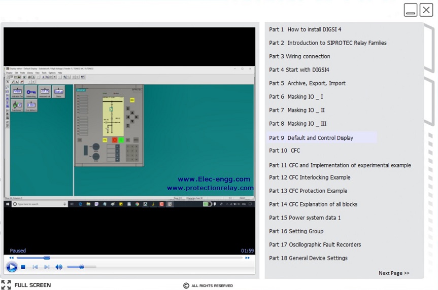
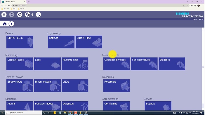
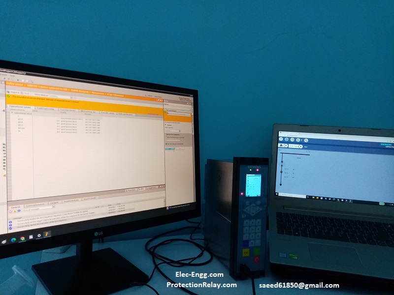
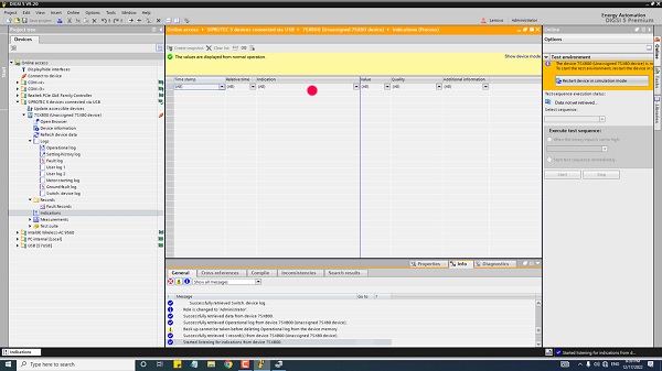
The spontaneous indication log which is available in online mode is a very good tool for testing and commissioning the SIPROTEC 5 devices. This log shows the indications immediately at the moment of occurrence (No wait for a cyclical update or initiating the manual update).

DIGSI 5 spontaneous indication

DIGSI 5 & SIPROTEC 5 topics:

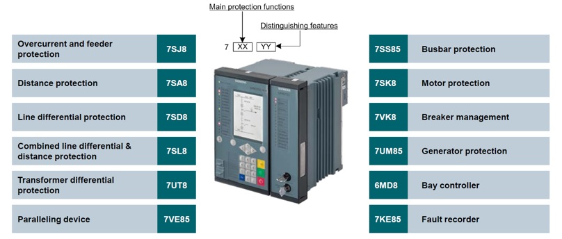
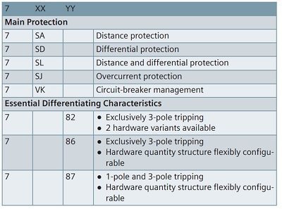
Parameter set, Connection to an online device, Updating firmware, showing truncated texts completely, Showing tooltips, The Add new device entry is an action. This lets you open a dialog to add a new SIPROTEC 5 device./ Open the Device View to configure the hardware of a SIPROTEC 5 device. Adjusting Working Area, Maximizing the DIGSI 5 working area, Minimizing DIGSI 5 working-area objects, Splitting the working area vertically or horizontally in DIGSI 5, Separating objects from the DIGSI 5 working area, Restoring the working area, Starting to Add Using the Project Tree in DIGSI 5, Single-line and display elements in DIGSI 5, Global DIGSI 5 Library, Starting to Add Using the Single-Line Configuration and the Library, Select Voltage Variant, Select function point class, And port J functionality, Application Template, Communication firmware version, Network view, and device view, Plug-in modules, Siprotec 5 online configurator, Update short product code list /TNS list, For instance, line protection, SIPROTEC 5 7SA, SIPROTEC 5 7sa82, SIPROTEC 5 7sa86, SIPROTEC 5 7sa87, SIPROTEC 5 7SJ, SIPROTEC 5 7SD, SIPROTEC 5 7SL, SIPROTEC 5 7VK, Overcurrent protection, phases 50/51, Overcurrent protection, ground 50N/51N, Directional overcurrent protection 67, Negative sequence 46, Voltage-dependent overcurrent protection 51V, Directional overcurrent protection, ground 67N

This package is a combination of IEC 61850, DIGSI 4, and DIGSI 5 courses. You can learn how to config SIPROTECT 4, and SIPROTECT 5, and IEC 61850. The material of each course is designed to help you and the training items are as follows:     

Product Detail:


SIPROTEC 4 and DIGSI 4 Training package (3hrs )
IEC 61850 Configuration (4 hrs )
SIPROTEC 5 and DIGSI 5 training package (7 hrs)

NAME length
Part 1: Substation Automation – an overview  05:39
Part 2: An introduction to IEC 61850 & how to learn it effectively 08:52
Part 3: Overview of the main features of IEC 61850 – Part I 08:58
Part 4: Overview of the main features of IEC 61850 – Part II 05:41
Part 5: IEC 61850 data structure and data format – Part I 33:34
Part 6: IEC 61850 data structure and data format – Part II 11:37
Part 7: IEC 61850 station in DIGSI 5 and IEC 61850 System Configurator 17:33
Part 8: GOOSE configuration and the publisher/subscriber LNs 14:34
Part 9: GOOSE simulation via IEDScout 06:31
Part 10: GOOSE configuration and simulation between SIP 5 & SEL relays 13:05
Part 11: Time synchronization settings and SNTP configuration 10:36
Part 12: Case study – Part I 14:56
Part 13: Case study – Part II 29:09
Part 14: Case study – Part III 23:41
Part 15: IEC 61850 configuration in DIGSI 4 20:03
Part 16: IEC 61850 configuration between SIP 4 & SIP 5 12:36
Part 17: Sample project 08:56

IEC 61850 Configuration (4 hrs-1.5 GB)

NAME length
Part 1: How to install DIGSI 4 01:57
PART 2: Introduction to SIPROTEC Relay families 06:50
Part 3: wiring connection 03:02
Part 4: start with DIGSI 19:12
part 5: Archive, import, export 12:36
Part 6: Masking I/O 11:00
Part 7: Masking I/O 04:51
Part 8: Masking I/O 13:08
Part 9: Default and Control Display 16:21
Part 10: CFC 11:57
Part 11: CFC and Implementation of experimental example 07:59
Part 12: CFC Interlocking Example 04:26
Part 13: CFC Protection Example 04:13
Part 14: CFC Explanation of all blocks 11:01
Part 15: Power system data 1 08:34
Part 16: Setting Group 19:13
Part 17: Oscillographic Fault Recorders 03:06
Part 18: General Device Settings 04:39
Part 19: Time Synchronization and Interfaces 03:40
Part 20: Device Driver and Firmware Update 09:04
Part 21: Config SIPROTEC relay in a Practical Project 14:36

DIGSI 5 Online Training

NAME length
part 1: SIPROTEC 5 relay families and applications 08:42
part 2: The online SIPROTEC 5 configurator 24:20
part 3: DIGSI 5 installation 04:27
part 4: DIGSI 5 upgrade and import device drivers 07:36
part 5: DIGSI 5 Vs DIGSI 4 16:05
Part 6:User interface and general setting 14:24
part 7: Case study relay configuration- part 1 16:57
part 8: SIPROTEC 5 Offline configuration I 15:31
part 9: Import specific communication drivers & inconsistencies 05:28
part 10: case study relay configuration- part 2 18:05
part 11: Distance relay configuration I 09:45
part 12: Distance relay configuration II 15:50
part 13: Distance relay configuration III 07:13
part 14: Function in DIGSI 5 16:07
part 15: case study relay configuration- part 3 12:40
part 16: case study relay configuration- part 4 05:48
part 17: case study relay configuration- part 5 15:57
part 18: case study relay configuration- part 6 17:45
part 19: Display Page configuration 15:38
part 20: case study relay configuration- part 7 10:06
part 21: CFC Configuration 09:08
part 22: CFC Analysis 06:13
part 23: CFC in DIGSI 5 and DIGSI 4 08:33
part 24: case study relay configuration- part 8 07:06
part 25: Case study busbar configuration- part 1 12:53
part 26: Case study busbar configuration- part 2 16:05
part 27: Case study busbar configuration- part 3 17:14
part 28: Case study busbar configuration- part 4 10:31
part 29: Case study busbar configuration- part 5 12:29
part 30: Case study busbar configuration- part 6 15:12
part 31: Case study busbar configuration- part 7 12:23
part 32: Case study busbar configuration- part 8 11:20
part 33: Case study busbar configuration- part 9 10:06
part 34: Case study busbar configuration- part 10 09:48
part 35: Case study busbar configuration- part 11 09:30

SIPROTEC 5 and DIGSI 5 training package

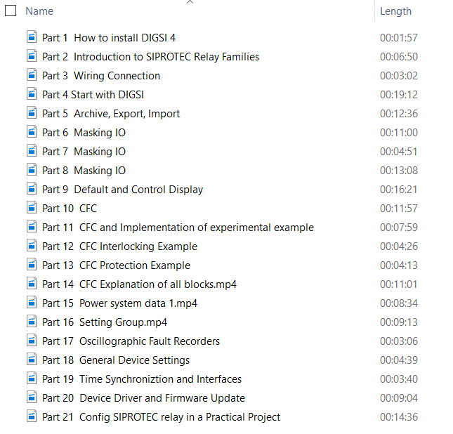
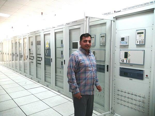
DIGSI 4 training will be taking you through the key stages of working with DIGSI 4 by using practical examples. This online course is suitable for electrical engineers with a desire to understand the fundamentals of configuring SIPROTECT 4 with DIGSI 4.

DIGSI 4 Online Training

Covered Items

Demo Video

What you learn:

  • Part 1 (01:57): How to install DIGSI 4
  • Part 2 (06:50): Introduction to SIPROTEC Relay Families
  • Part 3 (03:02): Wiring Connection
  • Part 4 (19:12): Start with DIGSI
  • Part 5 (12:36): Archive, Export, Import
  • Part 6 (11:00): Masking I/O
  • Part 7 (04:51): Masking I/O
  • Part 8 (13:08): Masking I/O
  • Part 9 (16:21): Default and Control Display
  • Part 10 (11:57): CFC
  • Part 11 (07:59): CFC and Implementation of Experimental Example
  • Part 12 (04:26): CFC Interlocking Example
  • Part 13 (04:13): CFC Protection Example
  • Part 14 (11:01): CFC Explanation of all blocks
  • Part 15 (08:34): Power system data 1
  • Part 16 (19:13): Setting Group
  • Part 17 (03:06): Oscillographic Fault Recorders
  • Part 18 (04:39): General Device Settings
  • Part 19 (03:40): Time Synchronization and Interfaces
  • Part 20 (09:04): Device Driver and Firmware Update
  • Part 21 (14:36): Config SIPROTEC relay in a Practical Project

Free Updates:

Updated on Dec 20, 2021: SIPROTEC 7UT6 config & setting description, and how to test differential function in SIPROTEC 7UT6

Certificate of completion for our enrolled members:

Other Courses: