Join our WhtsApp or Telegram groups by the click
Sample discussion in our WhatsApp group, Join Us for free discussion.
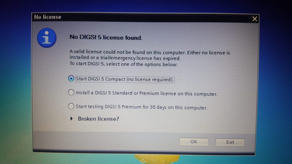
No DIGSI 5 license was found.
A valid license could not be found on this computer. Either no license is installed or a trial/emergency license has expired.
To start DIGSI 5, select one of the options below:
start DIGSI 5 Compact (no license required).
Install a DIGSI 5 Standard or premium license on this computer.
Start testing DIGSI 5 premium for 30 days on this computer.
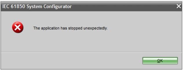
IEC 61850 System Configurator
The application has stopped unexpectedly.
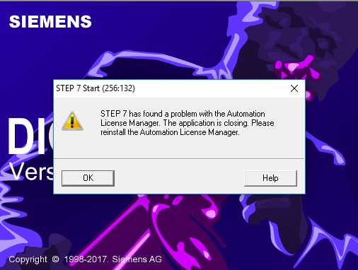
STEP 7- Start (256:132)
STEP 7 has found a problem with the Automation License Manager. The application is closing. Please reinstall the Automation License Manager.
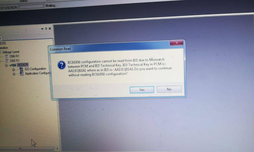
Common Read
IEC61850 configuration cannot be read from IED due to a Mismatch between PCM and IED Technical Key. IED Technical Key in PCM is:
AA1J1Q02A1 whereas in IED is AA1J1Q01A1.Do you want to continue without reading the IEC61850 configuration?
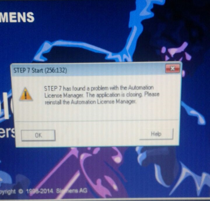
STEP 7 Start (256:132)
STEP 7 has found a problem with the Automation License Manager. The application is closing Please reinstall the Automation License Manager.
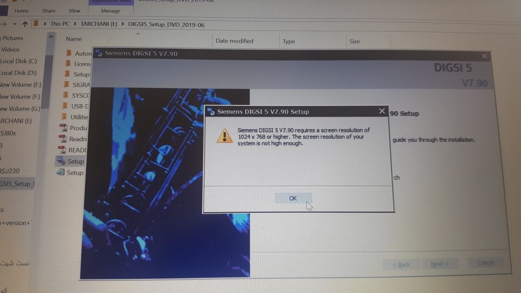
Siemens DIGSI 5 V7.90 Setup
Siemens DIGSI 5 V7.90 requires a screen with a resolution of 1024? 768 or higher. The screen resolution of your systems is not high enough.
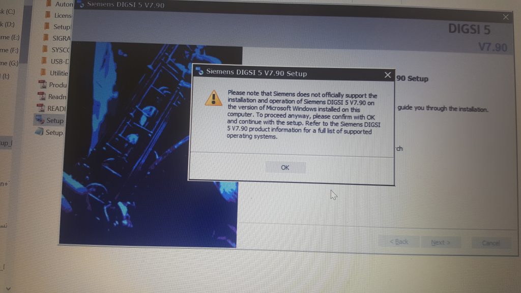
Siemens DIGSI 5 V7.90 Setup
Please note that Siemens does not officially support the installation and operation of Siemens DIGSI 5 V7.90 on the version of Microsoft Windows installed on this computer.
To proceed anyway, please confirm with OK and continue with the setup. Refer to the Siemens DIGSI 5 V7.90 product information for a full list of supported operating systems.
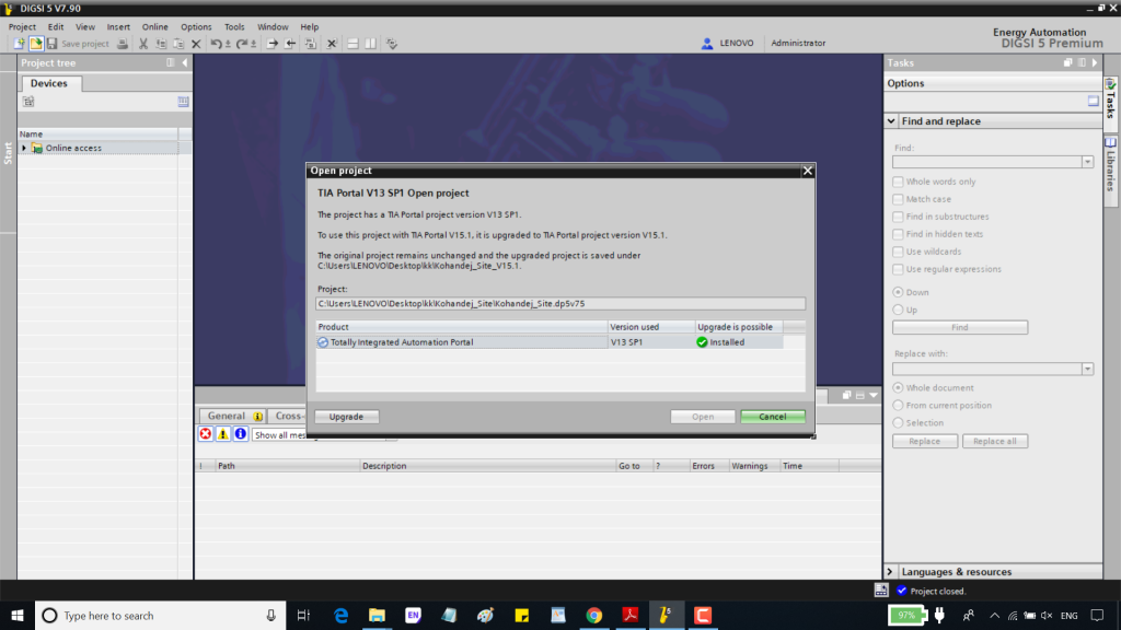
Open project
TIA Portal V13 SP1 Open project
The project has a TIA portal project version V13 SP1.
To use this project with TIA portal V15.1, it is upgraded to TIA portal project version V15.1.
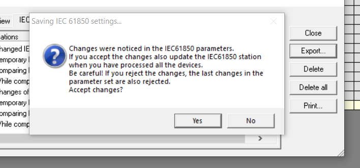
Chang was noticed in the IEC61850 parameters.
If you accept the changes also update the IEC61850 station when you have processed all the devices.
Be careful! If you reject the changes, the last changes in the parameter set are also rejected.
Accept changes?
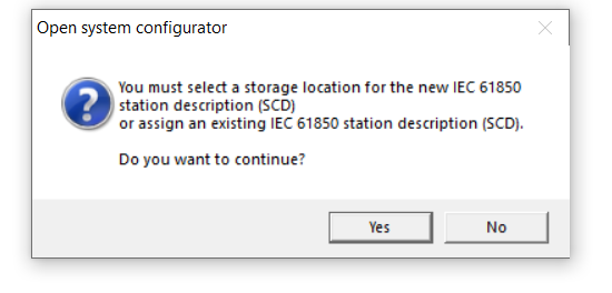
Open system configurator
You must select a storage location for the new IEC 61850 station description(SCD)
or assign an existing IEC 61850 station description (SCD).
Do you want to continue?
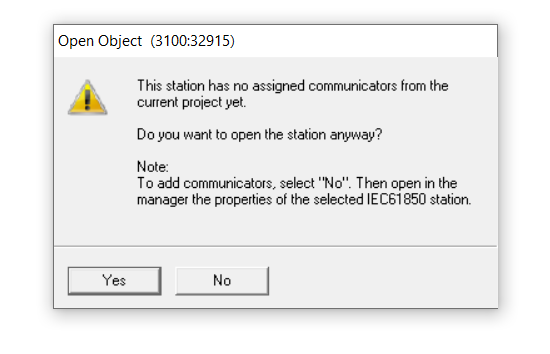
Open Object (3100:32915)
This station has no assigned communicators from the current project yet.
Do you want to open the station anyway?
Note:
To add Communicators, select “No”. Then open in the manager the properties of the selected IEC61850 station.
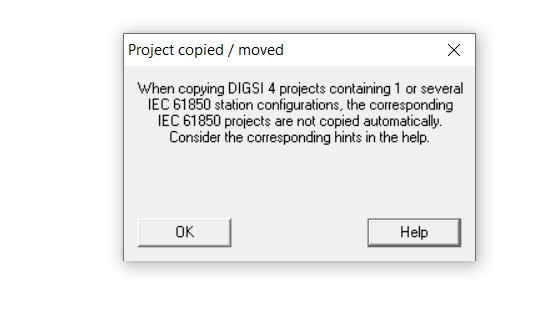
Project copied/moved
When copying DIGSI4 projects containing 1 or several IEC 61850 station configurations, the corresponding IEC 61850 projects are not copied automatically.
Consider the corresponding hints in help.
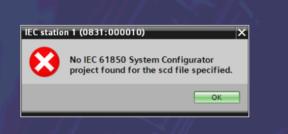
IEC station 1(0831:000010)
No IEC 61850 System Configurator
The project was found for the scd file specified.
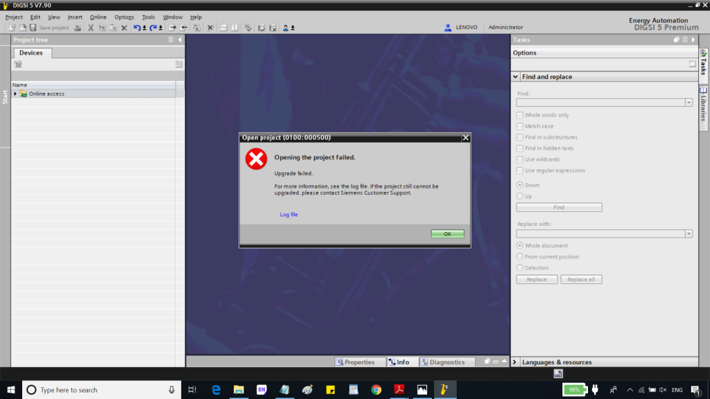
Open project(0100:000500)
Opening the project failed
Upgrade failed.
For more information, see the log file. If the project still cannot be upgraded. please contact Siemens Customer Support.
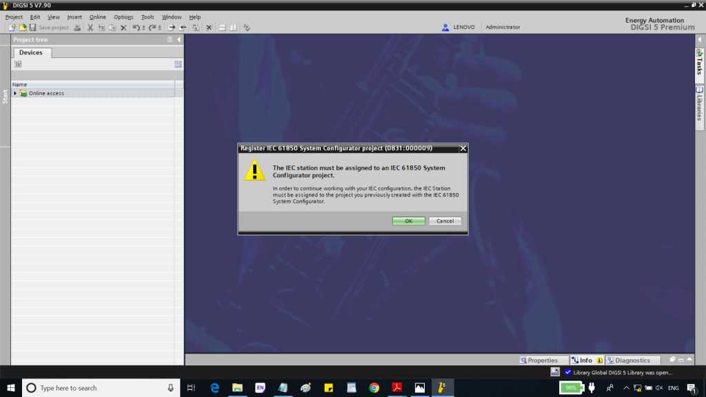
Register IEC 61850 System Configurator Project (0831:000009)
The IEC station must be assigned to an IEC 61850 System
Configurator project.
To continue working with your IEC configuration, the IEC Station.
must be assigned to the project you previously created with the IEC 61850 System Configurator.
Join our WhatsApp or Telegram groups by the link: https://elec-engg.com/whatsapp-group-for-protection-engineers/
Our completed Courses:
- IEC 61850 Configurator Training (4 Hrs)
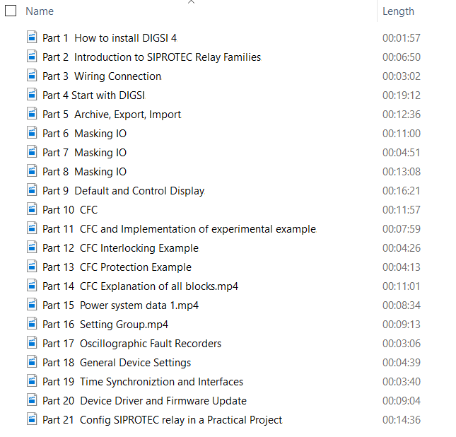
- DIGSI 4 Offline Video Training (3 Hrs)
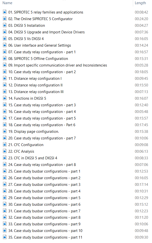
- DIGSI 5 Offline Video Training (7 Hrs)
- ETAP VIDEO Training (5.5)
- PSCAD Video Training (4 Hrs)
- PCM 600 Video Training (3 Hrs)
- MiCOM Relays Training Package (4 Hrs)
- Testing and Commissioning of Protective Relays


")