

Learning is a continuous process and enables us to be competitive in our field.
In this package, you get Trained DIGSI 4 and DIGSI 5 to work with SIPROTEC 4 & 5, how to work with Etap software, and how to use IEC 61850 for integration and communication between different equipment brands.
Product detail:
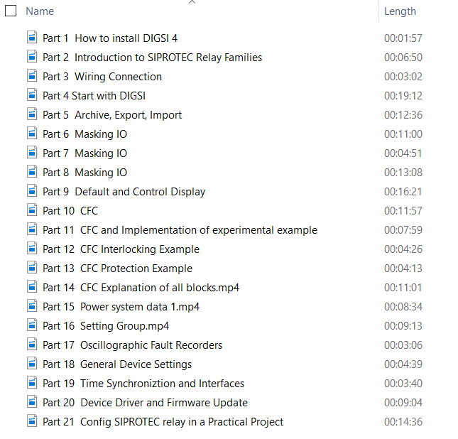
- DIGSI 4 video training (3 hrs)
- DIGSI 5 video training (7 hrs)
- IEC 61850 training (4 hrs)
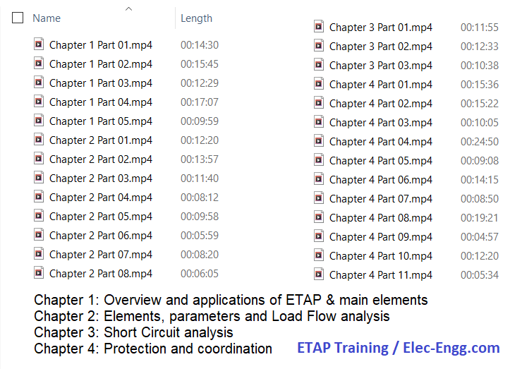
- ETAP for protection engineers (5.5 hrs)
- Trainer: Dr. Saeed Roostaee
- Language: English
- Full lifetime access
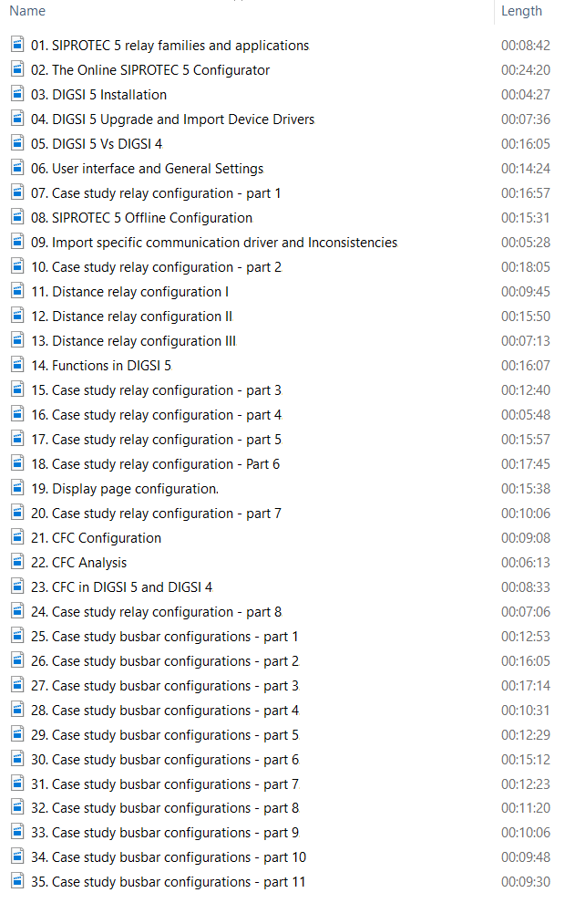


- DIGSI 5 Training: 435 Minutes – Full HD Size ( 1.9 GB), In English, By Dr. Saeed Roostaee
- DIGSI 4 Video Training: 185 Minutes, In English, By Dr. Saeed Roostaee
- IEC 61850 configuration Video Training: 4 hrs Language, In English, By Dr. Saeed Roostaee
- ETAP Video Training: 5.5 hrs, In English

contact us to get this impressive IEC61850 collection
- IEC 61850 Precision Time Protocol IEEE 1588
- IEC 61850 PRP Redundancy
- IEC 61850 Quality of Service
- IEC 61850 Redundancy Protocols
- IEC 61850 Substation Architecture
- IEC 61850 Substation Design Considerations
- IEC 61850 Time Synchronization
- IEEE 1588 – Master, Slave, and Transparent Clocks
- IEEE 1588 Synchronization Basics
- Important Properties of PTP
- Integrating Serial and IP Ethernet
- Introduction to IEEE 1588 Precision Time Protocol
- Network Management System Deployment Scenarios
- Network Management System Security
- Network Security- The Defense in Depth Model
- NMS User Guide- Device Discovery
- NMS User Guide- Permissions and Users
- NMS User Guide- Statistics
- NMS User Guide- Views and Alarms
- Product Overview – RAPTOREye
- PTP Profiles
- PTP Timing Requirements in Power Systems
- Securing a Switch and Functional Architecture
- Security Standards and the NERC CIP Framework
- Serial IP Conversion Use Case
- Switch Hardening_ Local Password and Access Authentication
- Switch Hardening- Finalizing the Security Configuration
- Switch Hardening- Secure Management and Configuration
- The Best Master Clock Algorithm
- The Gap Between Legacy Serial and Ethernet
- The Network Management System FCAPS Model
- Time Transfer Technology Comparison
- Virtual Serial Port Redirection
- What is a Network Management System (NMS)
- Name Size Date Modified
- Best Practice – Securing SNMP
- Best Practice_ Securing Management Protocols
- Best Practice- Enabling Remote Logging
- Best Practice- Time Sync, Disable Services, and Port Security
- Converting Serial to IP
- Core Redundancy and OSPF
- Defense in Depth Model
- Device Hardening- Best Practice Basics
- Device Level Security and Switch Functional Architecture
- Digital Substations- An Introduction to IEC 61850
- Ethernet Network Overview
- Gateway Redundancy – VRRP
- How does a VLAN work
- How PTP IEEE 1588 v2 Works
- HSR-PRP Redundancy
- IEC 61850 Communication Protocols
- IEC 61850 HSR Redundancy
- Interior Routing Protocol
- Layer 2 and Redundancy
- Layer 3 Concepts – Routing
- MAC and IP Addressing Format
- Managed vs Unmanaged Switch and Router
- Migration from Serial to Ethernet
- Redundancy Architecture from Substation to Control Center
- Redundant Network Timing Requirements
- Routing Functions and The Routing Table
- Static Routing vs. Dynamic Routing
- STP and RSTP Redundancy
- The Physical Layer
- VLAN Basics
- VLANs (IEEE 802.1Q)
- VLANs and Redundancy
- VLANs, Routing, and Cybersecurity
- What Is a Switch
- What is a VLAN
- What is Ethernet
- Bridging the Gap Ethernet, Serial, and Legacy Equipment in Substations
- Digital Substation Communications – What you Need to Know About IEC61850 Network Design
- Educational Training Introduction_ Networking 101 For OT Professionals
- IEC61850 Overview Video
- It’s about Time – Intro to IEEE 1588 and Precision Time Protocol
- Keeping an Eye Out_ Understanding Network Management Utilization
- Network Hardening, NERC CIP and the Smart Grid
- Network Redundancy- What Are Your Options- Why Choose One Technology over Another
- Networking 101 for OT Professionals_ Ethernet and its Application in Critical Utility Networks
- Networking 101 For OT Professionals- Making Sense of the Layers. Benefits of Layer 2 and Layer 3
- Switch Hardening Best Practices- How to Secure Your Industrial Network
- VLAN Fundamentals and Its Benefit in Network Design for Mission Critical Applications
- Name Size Date Modified
- Alex Apostolov about the past, present and the future of relay protection
- Christoph Brunner about origins of IEC 61850 and its future developments — Big Energy.
- IoT for Utility and Industrial Power Grids- Where Is the value-
- Route to IEC 61850 (2016)- The Concept of IEC 61850
- Route to IEC 61850- Engineering IEC 61850 systems
- Route to IEC 61850- HMI and Station Control
- Route to IEC 61850- Testing IEC 61850 Systems
- Route to IEC 61850- The Concept of IEC 61850
- Route to IEC 61850- Time Synchronization for IEC 61850
- The Future of Industrial Automation Video – GE Intelligent Platforms
- Welcome to the Digital Substation World I Episode 01
- ABB Goose config
- Cara Create ICD_SCD File (IEC61850 Protocol) dari Relay Reyrolle Argus 7SR
- Fiber Optic and Data Transferring between Substations and OTDR
- GE course
- GE DCS
- GE Geese confgi procedure

- Hands on Protection Testing using IEC 61850
- How to configure IEC 61850 with Easergy Studio
- How to enable Virtual Machine on Latest Windows Host Operating System
- How to generate the IEC 61850 MMS GOOSE Protocol traffic using SCL files with IEDScout
- How to perform the compare and find difference between the SCL files
- How to save the SCL file from IEDScout
- How to setup OpenSCD to be used in offline
- How to subscribe the GOOSE messages from third-party relays to ABB make relays in PCM600
- How to use IEDScout in offline and the benefits behind
- How to use IEDScout in offline to practic
- IEC 61850 implementation-related documentation for IEDs and Tools
- IEC 61850 Overview Part 9 SCL Files
- IEC 61850 programming training
- iec61850.
- ied scout
- Introduction and contents overview
- Introduction to packet sniffing and basics of communication protocols
- Making right connections to start sniffing in switched environment
- Start capturing with Wireshark and manage its basic settings
- Using Filters
- Working with packets
- Working with capture files
- Digital substation traffic capture analysis
- Practical demonstration
- IEDScout on MBX1 IEC 61850 IED Simulation with Positive use cases
- ieee1588
- OMICRON Customer Portal Overview
- Route to IEC 61850 (2016)- The Concept of IEC 61850
- SEL Goose config
- SETR850 schnider
- Simulating an IED from IEDScout PC with 102 port-occupied services
- StationScout offline benefits-Part-1
- STRATON IEC61850
- Trick Rahasia Edit CID File IEC61850 untuk Integrasi SIPROTEC5 PACIS Alstom
- Using IEC 61850 to Solve Protective Relaying Challenges (2011).mp4 292 M
- ABB webinar
- Awareness of IEC 61850 communication standard – Preface and tutors introduction
- digsi 4 iec61850 config
- digsi4 report
- easergy pro
- ethernet
- How does Modbus Communication Protocol Work
- IEC 61850 Data Modeling Part 2 – Triangle MicroWorks Inc
- IEC 61850 in the Modern Substation
- IEC 61850 Standard for T&D Grids
- iec 61850 webinar omicron
- IEC 61850
- IEC_61850_Simply_usable_mit_closing.
- iot – 38 – Lecture 3.3 Packet Capture Demo
- Mensajes GOOSE en IEC61850 de Siemens
- omicron goose
- omicron products
- omicron SV
- Relational Database Concepts
- sip5 iec61850
- triangle
- Practical IEC 61850 for Substation Automation for Engineers and Technicians
- Video Session 2- Practical IEC 61850 for Substation Automation for Engineers and Technicians
- Video Session 3- Practical IEC 61850 for Substation Automation for Engine
- What is OSI Model

- What is the IEC 61850 protocol- How does it work- What’s the difference with other protocols
- SIPROTEC 5 certificate automation – using Enrollment over Secure Transport protocol
- Webinar SIPROTEC 5 certificate Secure Transport EST protocol
- Expert Talk – Overview of SICAM A8000, SIAPP & Web HMI
- Global Summit 2022 Digital switchgears for intelligent secondary distribution grid automation
- Global Summit 2022 Behind the scenes– Self optimized grid to the largest onshore fish farm in Norway
- Global Summit 2022 Conference Digital switchgear solutions for primary distribution
- Global Summit 2022 Conference Precisely tailored substation automation with SICAM A8000
- Global Summit 2022 Keynote Innovative technologies in electrification & automation for our future
- Global Summit 2022 Mastering distribution grid diversification by IoT SIPROTEC5
- Global Summit 2022 SICAM A8000 beyond the typical substation automation–New apps for the Etransition
- Global Summit 2022 Training How to write your own application for SICAM A8000 with SIAPP
- Migration of SICAM TOOLBOX II configuration
- SICAM Earth Fault Indicator – SICAM EFI Introduction Animation (FR)
- SICAM Earth Fault Indicator – SICAM EFI Introduction Animation
- Automation and remote terminal units SICAM A8000 RTU SIPROTEC-5 SIEMENS
- Sicam Application CP8050 Automation and remote terminal units A8000 RTU SIPROTE
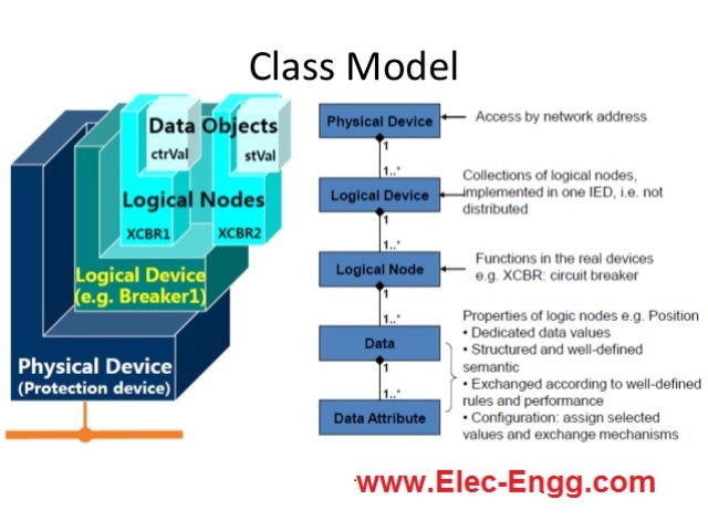


ABB CAP 505 (Computer Aided Programming system) can be used to config the ABB RED 500 and SPACOM series. This training course introduces the hardware structure of the RE 500 series and then the configuration procedure of these relays in CAP 505.
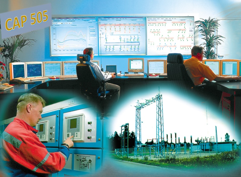
Pre-recorded Videos
- Part 01: RE 500 relay hardware explanation (26 minutes)
- Part 02: CAP 505 user interface, create a project, and add relay REF 54 (13 minutes)
- Part 03: Create project structure (16 minutes)
- Part 04: Function blocks and IO configuration (8 minutes)
- Part 05: Blocking signal by inrush and Fuse failure (9 minutes)
- Part 06: Config Trip signals (4 minutes).
- part 07: Measurements and LEDs configuration (5 minutes).
- Part 08: Disturbance recorder configuration (3 minutes).
- Part 09: LCD configuration (8 minutes).
- Part 10: settings and download to the relay (15 minutes).
Course Contents:
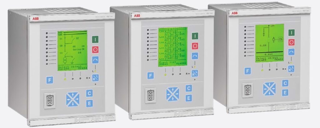
- The hardware structure of ABB RE 500 series (REM543, REF543, REM545, REF 541, REF543, …)
- Introduce the CAP 505 and the user interface (Caption bar, Toolbar, Project Structure, Status bar, Status bar, Menu bar)
- Create a new project and add a case study relay (manage the project, project structurization, add new Rlay REF 543, The configuration dialog for REF54x device, add communication port)
- Create project structure (define the library, add Logical POUs, Physical hardware config, resources, tasks, assign tasks, …)
- Add function block and config Inputs and outputs ( add directional Overcurretn and Direction earthfall functions, Config analog inputs, binary inputs, and binary outputs, …)
- LED, LCD, measurement, and disturbance configuration (Config trip signals to the LEDs, config measurements to the LCD, Config the breaker position to the LCD)
- Settings and upload/download (explain the main parameters of the Directional overcurrent, Direcinal earth fault, disturbance recorder, Fuse fail, inrush current, …)

How to access the training course
Buy now and start learning:

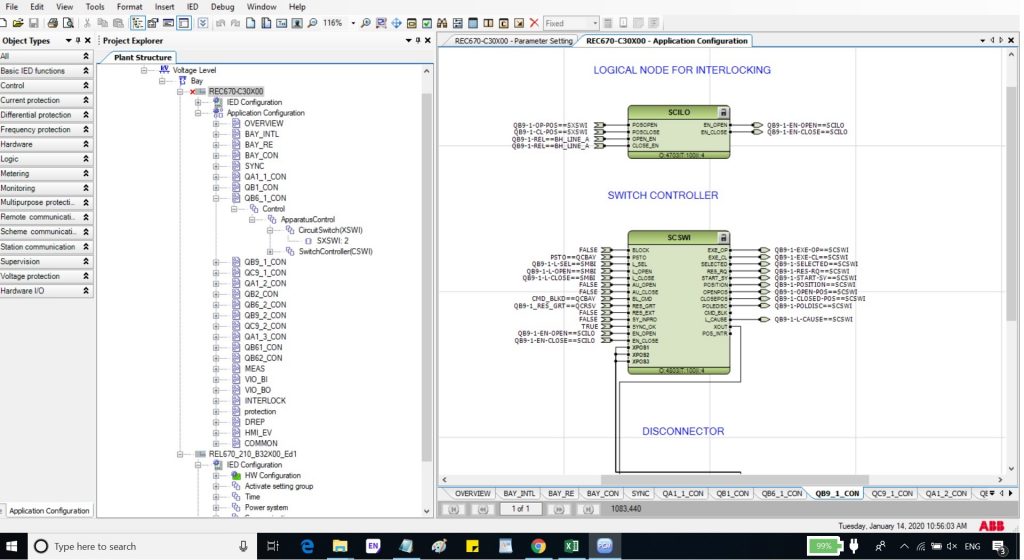
- PCM 600 Introduction
- Communication and project setup in PCM 600
- Update Manager tool
- Hardware Configuration tool
- Read from IED
- Write to IED
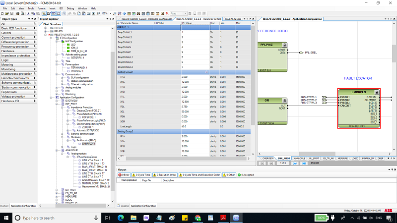
- Application configuration in PCM 600
- Signal Matrix tool
- Parameter Setting tool
- Signal matrix and parameter setting in PCM 600
- Interlinking between Signal Matrix tool and Application configuration tool
- IED Compare tool
- Disturbance Handlin tool
- Signal Monitoring tool
- PCM 600 Monitoring
- Graphical Display Editor in PCM 600
- Graphical display editor
- Migrate configuration tool
- PCM Options
- IED user Management tool
- Scheduler
- Set Technical Key tool
- Goose Communication engineering (GCB)
- Changing the SCL version of IED
- Client-Server engineering (RCB) for vertical communication


Prerequisite Training packages
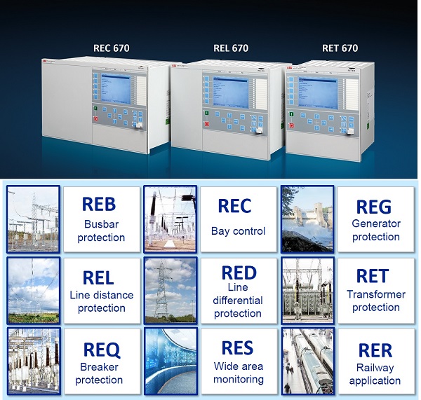
ABB REG670 Training package (Advanced level)
- Trainer: Dr. Saeed Roostaee (Profile on Linkedin)
- Pre-recorded videos
- Supplementary Files
- The course is still being recorded and new sessions will be added over time
- The course is licensed and you need a Windows computer to view the videos
- Download this course: contact us or leave a comment on this post
- For more info, please leave a comment on this post or contact us on WhatsApp: +989129613659
Course Details:
Configuration in the PCM600
- Generator, GSU, ET Transformer Unit Protection System
- Analog inputs, Generator & Transformer- CT and VT
- Generator protection functions (87G, 40G, 78, 50S, 46, 51V, 49S, 59, 27, 21G, 32R, 50/27, 64GB, 64R, 47, 64s-95 &100%, 81 O&U, 24G)
- GSU Trans Protection Functions (87T, 87GT, 64T(87N), 51N, 50/51T)
- Excitation Trans Protection Functions (50.51ET, 49ET)
- Trip matrix, Blocking logic
- Binary Outputs, LED Signal, Output Contact test
- Disturbance recorder
- IEC 61850 Signals
Parameter setting and Relay calculations
- 87G Generator Differential Protection
- 87T GSU Trans. Differential Protection
- 87GT Overall Differential Protection
- 40G Generator Field Failure Protection
- 78G Generator Pole Slipping Protection
- 50S, Generator Split phase overcurrent protection
- 46 Generator Negative Phase Sequence Protection
- 51V Generator Voltage-Dependent O/C Protection
- 49S Generator Stator Overload Protection
- 59G Generator Overvoltage Protection
- 21G Generator Underimpedance Protection
- 27G Generator Undervoltage Protection
- 32R Generator Reverse Power Protection
- 64S Generator 95%&100% Stator Earth Fault Protection
- 51/27 Generator Dead Machine Protection
- 64GB Generator Busbar Earth Fault Protection
- 64R Generator Rotor Earth Fault Protection
- 81O Generator Overfrequency Protection
- 81U Generator Underfrequency Protection
- 24G Generator Overflux Protection
- 47G Generator Fuse Failure Supervision
- 50/51ET Excitation Trans. Overcurrent Protection
- 49ET Excitation Trans. Overload Protection
- 51N-GSU Gen. Step-up Trans. Neutral Point OvercurrentProtection
- 64T GSU Trans. Restricted Earth Fault Protection
- 50/51T GSU Trans. Over Current Protection
- 50/51SST Station Service Trans. Over Current Protection
Click here to enroll in the course and get the certificate of the IEC 61850 compilation course
https://elec-engg.com/iec-61850-training-course/
- IEC 61850 TRAINING CERTIFICATE NUMBER C 1000: Click here to download
- IEC 61850 TRAINING CERTIFICATE NUMBER C 1001: Click here to download
- IEC 61850 TRAINING CERTIFICATE NUMBER C 1002: Click here to download
- IEC 61850 TRAINING CERTIFICATE NUMBER C 1003: Click here to download
- IEC 61850 TRAINING CERTIFICATE NUMBER C 1004: Click here to download
- IEC 61850 TRAINING CERTIFICATE NUMBER C 1005: Click here to download
- IEC 61850 TRAINING CERTIFICATE NUMBER C 1006: Click here to download
- IEC 61850 TRAINING CERTIFICATE NUMBER C 1007: Click here to download
- IEC 61850 TRAINING CERTIFICATE NUMBER C 1008: Click here to download
- IEC 61850 TRAINING CERTIFICATE NUMBER C 1009: Click here to download
- IEC 61850 TRAINING CERTIFICATE NUMBER C 1010: Click here to download
- IEC 61850 TRAINING CERTIFICATE NUMBER C 1011: Click here to download
- IEC 61850 TRAINING CERTIFICATE NUMBER C 1012: Click here to download
- IEC 61850 TRAINING CERTIFICATE NUMBER C 1013: Click here to download
- IEC 61850 TRAINING CERTIFICATE NUMBER C 1014: Click here to download
- IEC 61850 TRAINING CERTIFICATE NUMBER C 1015: Click here to download
- IEC 61850 TRAINING CERTIFICATE NUMBER C 1016: Click here to download
- IEC 61850 TRAINING CERTIFICATE NUMBER C 1017: Click here to download
- IEC 61850 TRAINING CERTIFICATE NUMBER C 1018: Click here to download
- IEC 61850 TRAINING CERTIFICATE NUMBER C 1019: Click here to download
- IEC 61850 TRAINING CERTIFICATE NUMBER C 1020: Click here to download
- IEC 61850 TRAINING CERTIFICATE NUMBER C 1021: Click here to download
- IEC 61850 TRAINING CERTIFICATE NUMBER C 1022: Click here to download
- IEC 61850 TRAINING CERTIFICATE NUMBER C 1023: Click here to download
- IEC 61850 TRAINING CERTIFICATE NUMBER C 1024: Click here to download
- IEC 61850 TRAINING CERTIFICATE NUMBER C 1025: Click here to download
- IEC 61850 TRAINING CERTIFICATE NUMBER C 1026: Click here to download
- IEC 61850 TRAINING CERTIFICATE NUMBER C 1027: Click here to download
- IEC 61850 TRAINING CERTIFICATE NUMBER C 1028: Click here to download
- IEC 61850 TRAINING CERTIFICATE NUMBER C 1029: Click here to download
- IEC 61850 TRAINING CERTIFICATE NUMBER C 1030: Click here to download
- IEC 61850 TRAINING CERTIFICATE NUMBER C 1031: Click here to download
- IEC 61850 TRAINING CERTIFICATE NUMBER C 1032: Click here to download
- IEC 61850 TRAINING CERTIFICATE NUMBER C 1033: Click here to download
- IEC 61850 TRAINING CERTIFICATE NUMBER C 1034: Click here to download
- IEC 61850 TRAINING CERTIFICATE NUMBER C 1035: Click here to download
- IEC 61850 TRAINING CERTIFICATE NUMBER C 1036: Click here to download
- IEC 61850 TRAINING CERTIFICATE NUMBER C 1037: Click here to download
- IEC 61850 TRAINING CERTIFICATE NUMBER C 1038: Click here to download
- IEC 61850 TRAINING CERTIFICATE NUMBER C 1039: Click here to download
- IEC 61850 TRAINING CERTIFICATE NUMBER C 1040: Click here to download
- IEC 61850 TRAINING CERTIFICATE NUMBER C 1041: Click here to download
- IEC 61850 TRAINING CERTIFICATE NUMBER C 1042: Click here to download
- IEC 61850 TRAINING CERTIFICATE NUMBER C 1043: Click here to download
- IEC 61850 TRAINING CERTIFICATE NUMBER C 1044: Click here to download
- IEC 61850 TRAINING CERTIFICATE NUMBER C 1045: Click here to download
- IEC 61850 TRAINING CERTIFICATE NUMBER C 1046: Click here to download
- IEC 61850 TRAINING CERTIFICATE NUMBER C 1047: Click here to download
- IEC 61850 TRAINING CERTIFICATE NUMBER C 1048: Click here to download
- IEC 61850 TRAINING CERTIFICATE NUMBER C 1049: Click here to download
- IEC 61850 TRAINING CERTIFICATE NUMBER C 1050: Click here to download
- IEC 61850 TRAINING CERTIFICATE NUMBER C 1051: Click here to download
- IEC 61850 TRAINING CERTIFICATE NUMBER C 1052:Click here to download
- IEC 61850 TRAINING CERTIFICATE NUMBER C 1053: Click here to download
- IEC 61850 TRAINING CERTIFICATE NUMBER C 1054: Click here to download
- IEC 61850 TRAINING CERTIFICATE NUMBER C 1055: Click here to download
- IEC 61850 TRAINING CERTIFICATE NUMBER C 1056: Click here to download
- IEC 61850 TRAINING CERTIFICATE NUMBER C 1057: Click here to download
- IEC 61850 TRAINING CERTIFICATE NUMBER C 1058: Click here to download
- IEC 61850 TRAINING CERTIFICATE NUMBER C 1059: Click here to download
- IEC 61850 TRAINING CERTIFICATE NUMBER C 1060: Click here to download
- IEC 61850 TRAINING CERTIFICATE NUMBER C 1061: Click here to download
- IEC 61850 TRAINING CERTIFICATE NUMBER C 1062: Click here to download
- IEC 61850 TRAINING CERTIFICATE NUMBER C 1063: Click here to download
- IEC 61850 TRAINING CERTIFICATE NUMBER C 1064: Click here to download
- IEC 61850 TRAINING CERTIFICATE NUMBER C 1065: Click here to download
- IEC 61850 TRAINING CERTIFICATE NUMBER C 1066: Click here to download
- IEC 61850 TRAINING CERTIFICATE NUMBER C 1067: Click here to download
- IEC 61850 TRAINING CERTIFICATE NUMBER C 1068: Click here to download
- IEC 61850 TRAINING CERTIFICATE NUMBER C 1069: Click here to download
- IEC 61850 TRAINING CERTIFICATE NUMBER C 1070: Click here to download
- IEC 61850 TRAINING CERTIFICATE NUMBER C 1071: Click here to download
- IEC 61850 TRAINING CERTIFICATE NUMBER C 1072: Click here to download
- IEC 61850 TRAINING CERTIFICATE NUMBER C 1073: Click here to download
- IEC 61850 TRAINING CERTIFICATE NUMBER C 1074: Click here to download
- IEC 61850 TRAINING CERTIFICATE NUMBER C 1075: Click here to download
- IEC 61850 TRAINING CERTIFICATE NUMBER C 1076: Click here to download
- IEC 61850 TRAINING CERTIFICATE NUMBER C 1077: Click here to download
- IEC 61850 TRAINING CERTIFICATE NUMBER C 1078: Click here to download
- IEC 61850 TRAINING CERTIFICATE NUMBER C 1079: Click here to download
- IEC 61850 TRAINING CERTIFICATE NUMBER C 1080: Click here to download
- IEC 61850 TRAINING CERTIFICATE NUMBER C 1081: Click here to download
- IEC 61850 TRAINING CERTIFICATE NUMBER C 1082: Click here to download
- IEC 61850 TRAINING CERTIFICATE NUMBER C 1083: Click here to download
- IEC 61850 TRAINING CERTIFICATE NUMBER C 1084: Click here to download
- IEC 61850 TRAINING CERTIFICATE NUMBER C 1085: Click here to download
- IEC 61850 TRAINING CERTIFICATE NUMBER C 1086: Click here to download
- IEC 61850 TRAINING CERTIFICATE NUMBER C 1087: Click here to download
- IEC 61850 TRAINING CERTIFICATE NUMBER C 1088: Click here to download
- IEC 61850 TRAINING CERTIFICATE NUMBER C 1089: Click here to download
- IEC 61850 TRAINING CERTIFICATE NUMBER C 1090: Click here to download
- IEC 61850 TRAINING CERTIFICATE NUMBER C 1091: Click here to download
- IEC 61850 TRAINING CERTIFICATE NUMBER C 1092: Click here to download
- IEC 61850 TRAINING CERTIFICATE NUMBER C 1093: Click here to download
- IEC 61850 TRAINING CERTIFICATE NUMBER C 1094: Click here to download
- IEC 61850 TRAINING CERTIFICATE NUMBER C 1095: Click here to download
- IEC 61850 TRAINING CERTIFICATE NUMBER C 1096: Click here to download
- IEC 61850 TRAINING CERTIFICATE NUMBER C 1097: Click here to download
- IEC 61850 TRAINING CERTIFICATE NUMBER C 1098: Click here to download
- IEC 61850 TRAINING CERTIFICATE NUMBER C 1099: Click here to download
- IEC 61850 TRAINING CERTIFICATE NUMBER C 1100: Click here to download
- IEC 61850 TRAINING CERTIFICATE NUMBER C 1101: Click here to download
- IEC 61850 TRAINING CERTIFICATE NUMBER C 1102: Click here to download
- IEC 61850 TRAINING CERTIFICATE NUMBER C 1103: Click here to download
- IEC 61850 TRAINING CERTIFICATE NUMBER C 1104: Click here to download
- IEC 61850 TRAINING CERTIFICATE NUMBER C 1105:Click here to download
- IEC 61850 TRAINING CERTIFICATE NUMBER C 1106: Click here to download
- IEC 61850 TRAINING CERTIFICATE NUMBER C 1107: Click here to download
- IEC 61850 TRAINING CERTIFICATE NUMBER C 1108: Click here to download
- IEC 61850 TRAINING CERTIFICATE NUMBER C 1109: Click here to download
- IEC 61850 TRAINING CERTIFICATE NUMBER C 1110:Click here to download
- IEC 61850 TRAINING CERTIFICATE NUMBER C 1111: Click here to download
- IEC 61850 TRAINING CERTIFICATE NUMBER C 1112: Click here to download
- IEC 61850 TRAINING CERTIFICATE NUMBER C 1113: Click here to download
- IEC 61850 TRAINING CERTIFICATE NUMBER C 1114: Click here to download
- IEC 61850 TRAINING CERTIFICATE NUMBER C 1115: Click here to download
- IEC 61850 TRAINING CERTIFICATE NUMBER C 1116: Click here to download
- IEC 61850 TRAINING CERTIFICATE NUMBER C 1117: Click here to download
- IEC 61850 TRAINING CERTIFICATE NUMBER C 1118: Click here to download
- IEC 61850 TRAINING CERTIFICATE NUMBER C 1119: Click here to download
- IEC 61850 TRAINING CERTIFICATE NUMBER C 1120: Click here to download
- IEC 61850 TRAINING CERTIFICATE NUMBER C 1121: Click here to download
- IEC 61850 TRAINING CERTIFICATE NUMBER C 1122: Click here to download
- IEC 61850 TRAINING CERTIFICATE NUMBER C 1123: Click here to download
- IEC 61850 TRAINING CERTIFICATE NUMBER C 1124: Click here to download
- IEC 61850 TRAINING CERTIFICATE NUMBER C 1125: Click here to download
- IEC 61850 TRAINING CERTIFICATE NUMBER C 1126: Click here to download
- IEC 61850 TRAINING CERTIFICATE NUMBER C 1127: Click here to download
- IEC 61850 TRAINING CERTIFICATE NUMBER C 1128: Click here to download
- IEC 61850 TRAINING CERTIFICATE NUMBER C 1129:Click here to download
- IEC 61850 TRAINING CERTIFICATE NUMBER C 1130: Click here to download
- IEC 61850 TRAINING CERTIFICATE NUMBER C 1131: Click here to download
- IEC 61850 TRAINING CERTIFICATE NUMBER C 1132: Click here to download
- IEC 61850 TRAINING CERTIFICATE NUMBER C 1133: Click here to download
- IEC 61850 TRAINING CERTIFICATE NUMBER C 1134: Click here to download
- IEC 61850 TRAINING CERTIFICATE NUMBER C 1135: Click here to download
- IEC 61850 TRAINING CERTIFICATE NUMBER C 1136: Click here to download
- IEC 61850 TRAINING CERTIFICATE NUMBER C 1137: Click here to download
- IEC 61850 TRAINING CERTIFICATE NUMBER C 1138: Click here to download
- IEC 61850 TRAINING CERTIFICATE NUMBER C 1139: Click here to download
- IEC 61850 TRAINING CERTIFICATE NUMBER C 1140: Click here to download
- IEC 61850 TRAINING CERTIFICATE NUMBER C 1141: Click here to download
- IEC 61850 TRAINING CERTIFICATE NUMBER C 1142: Click here to download
- IEC 61850 TRAINING CERTIFICATE NUMBER C 1143: Click here to download
- IEC 61850 TRAINING CERTIFICATE NUMBER C 1144: Click here to download
- IEC 61850 TRAINING CERTIFICATE NUMBER C 1145: Click here to download
- IEC 61850 TRAINING CERTIFICATE NUMBER C 1146: Click here to download
- IEC 61850 TRAINING CERTIFICATE NUMBER C 1147: Click here to download
- IEC 61850 TRAINING CERTIFICATE NUMBER C 1148: Click here to download
- IEC 61850 TRAINING CERTIFICATE NUMBER C 1149: Click here to download
- IEC 61850 TRAINING CERTIFICATE NUMBER C 1150: Click here to download
- IEC 61850 TRAINING CERTIFICATE NUMBER C 1151: Click here to download
- IEC 61850 TRAINING CERTIFICATE NUMBER C 1152: Click here to download
- IEC 61850 TRAINING CERTIFICATE NUMBER C 1153: Click here to download
- IEC 61850 TRAINING CERTIFICATE NUMBER C 1154: Click here to download
- IEC 61850 TRAINING CERTIFICATE NUMBER C 1155: Click here to download
- IEC 61850 TRAINING CERTIFICATE NUMBER C 1156: Click here to download
- IEC 61850 TRAINING CERTIFICATE NUMBER C 1157: Click here to download
- IEC 61850 TRAINING CERTIFICATE NUMBER C 1158: Click here to download
- IEC 61850 TRAINING CERTIFICATE NUMBER C 1159: Click here to download
- IEC 61850 TRAINING CERTIFICATE NUMBER C 1160: Click here to download
- IEC 61850 TRAINING CERTIFICATE NUMBER C 1161: Click here to download
- IEC 61850 TRAINING CERTIFICATE NUMBER C 1162: Click here to download
- IEC 61850 TRAINING CERTIFICATE NUMBER C 1163: Click here to download
- IEC 61850 TRAINING CERTIFICATE NUMBER C 1164: Click here to download
- IEC 61850 TRAINING CERTIFICATE NUMBER C 1165: Click here to download
- IEC 61850 TRAINING CERTIFICATE NUMBER C 1166: Click here to download
- IEC 61850 TRAINING CERTIFICATE NUMBER C 1167: Click here to download
- IEC 61850 TRAINING CERTIFICATE NUMBER C 1168: Click here to download
- IEC 61850 TRAINING CERTIFICATE NUMBER C 1169: Click here to download
- IEC 61850 TRAINING CERTIFICATE NUMBER C 1170: Click here to download
- IEC 61850 TRAINING CERTIFICATE NUMBER C 1171: Click here to download
- IEC 61850 TRAINING CERTIFICATE NUMBER C 1172: Click here to download
- IEC 61850 TRAINING CERTIFICATE NUMBER C 1173: Click here to download
- IEC 61850 TRAINING CERTIFICATE NUMBER C 1174: Click here to download
- IEC 61850 TRAINING CERTIFICATE NUMBER C 1175: Click here to download
- IEC 61850 TRAINING CERTIFICATE NUMBER C 1176: Click here to download
- IEC 61850 TRAINING CERTIFICATE NUMBER C 1177: Click here to download
- IEC 61850 TRAINING CERTIFICATE NUMBER C 1178: Click here to download
- IEC 61850 TRAINING CERTIFICATE NUMBER C 1179: Click here to download
- IEC 61850 TRAINING CERTIFICATE NUMBER C 1180: Click here to download
- IEC 61850 TRAINING CERTIFICATE NUMBER C 1181: Click here to download
- IEC 61850 TRAINING CERTIFICATE NUMBER C 1182: Click here to download
- IEC 61850 TRAINING CERTIFICATE NUMBER C 1183: Click here to download
- IEC 61850 TRAINING CERTIFICATE NUMBER C1184: Click here to download
- IEC 61850 TRAINING CERTIFICATE NUMBER C 1185: Click here to download
- IEC 61850 TRAINING CERTIFICATE NUMBER C 1186: Click here to download
- IEC 61850 TRAINING CERTIFICATE NUMBER C 1187: Click here to download
- IEC 61850 TRAINING CERTIFICATE NUMBER C 1188: Click here to download
- IEC 61850 TRAINING CERTIFICATE NUMBER C 1189: Click here to download
- IEC 61850 TRAINING CERTIFICATE NUMBER C 1190: Click here to download
- IEC 61850 TRAINING CERTIFICATE NUMBER C 1191: Click here to download

Training delivery: Face-to-face / Online sections on Google Meet + pre-recorded videos
Trainer: Dr. Saeed Roostaee
What you’ll learn
- Packet sniffing approaches and tools
- How to connect to switched network infrastructure to capture required data
- How to start with Wireshark and its basic settings
- How do you use capture and display filters in Wireshark?
- Tips and tricks on working with packets
- Tips and tricks on working with capture files
- How to analyze GOOSE, Sampled Values, and MMS traffic with Wireshark
- Practical examples
- Capture and interpret network traffic with Wireshark
- Understand core networking protocols – DHCP, DNS, TCP/IP
- Troubleshoot the top five network problems with Wireshark
- Analyze a cybersecurity attack with Wireshark
Content
Using Wireshark for traffic analysis in digital substations
- Introduction and Contents Overview
- Installing Wireshark and the Command Line Tools
- Introduction to packet sniffing and basics of communication protocols
- What are Wireshark Profiles and Why Should We Use Them?
- Hands-On with Wireshark
- Configuring Profiles, Adding Custom Columns
- Configuring the Wireshark Interface
- Making the right connections to start sniffing in a switched environment
- Start capturing with Wireshark and manage its basic settings
- Introduction to Wireshark Filters
Capture filters Vs display filters - Filtering for IP Addresses, Source or Destination
- Filtering for Protocols and Port Numbers
- Filtering for conversations
- Operators in display filters
- Working with packets
- Working with capture files
- Creating Display Filters in Wireshark
- Packets and the OSI Model
- Ethernet – The Frame Header
- Unicasts vs Broadcasts vs Multicasts
- The Internet Protocol – Learning the Header Values
- Following a Packet Through the Network – Re-Encapsulation
- Analyzing a Packet From Multiple Capture Points
- How IP Fragmentation Works
- The UDP Header Explained
- UDP Review
- Practical TCP – The Handshake
- Analyzing TCP Options
- How Sequence and Acknowledgement Numbers Work
- Slow application response time
- High Network Latency
- Network Packet Loss
- TCP Analysis Review
- Digital substation traffic capture analysis
- Practical demo with Wireshark

- Trainer: Dr. Saeed Roostaee (Profile)
- Pre-recorded videos with online access+Free updates +Free certification +Free technical support
Content:
Supplementary Files: The important related files/ videos /software and attached to the course as extra files.
Any queries, please feel free to contact me at: saeed61850@gmail.com
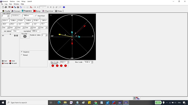
Part A: Introduction, general settings, Hardware & connection, Impedance/Vector/report View, the test object, …
- A 01 (Length: 02 min, Update: Oct 3, 2021): Introduction
- A 02 (Length: 05 min, Update: Oct 3, 2021): Strat page (Omicron)
- A 03 (Length: 06 min, Update: Oct 3, 2021): General settings (Omicron)
- A 04 (Length: 05 min, Update: Oct 3, 2021): Strat page (Vebko)
- A 05 (Length: 14 min, Update: Oct 3, 2021): Phasor view, Impedance view (Omicron)
- A 06 (Length: 06 min, Update: Oct 3, 2021): Phasor view, Impedance view, differential view (Vebko)
- A 07 (Length: 04 min, Update: Oct 3, 2021): Hardware connection
- A 08 (Length: 10 min, Update: Oct 3, 2021): Practical section with Omicron 256 plus, SEL 421
Part B: Overcurrent and Directional Overcurrent Functions (67, 67N, 50, 51, 50N, 51N)
- B 01 (Length: 19 min, Update: Oct 3, 2021): Test object, Overcurrent RIO block, testing of overcurrent
- B 02 (Length: 16 min, Update: Oct 3, 2021): Settings of the Overcurrent test module
- B 03 (Length: 15 min, Update: Oct 3, 2021): Practical section
- B 04 (Length: 17 min, Update: Oct 3, 2021): Practical section
- B 05 (Length: 06 min, Update: Oct 3, 2021): Practical section
- B 06 (Length: 15 min, Update: Oct 3, 2021): Practical section
- B 07 (Length: 09 min, Update: Oct 3, 2021): Practical section
- B 08 (Length: 15 min, Update: Oct 3, 2021): Practical section
- B 09 (Length: 22 min, Update: Oct 3, 2021): Practical section
- B 10 (Length: 23 min, Update: Oct 3, 2021): Practical section (directional overcurrent concepts, settings, practice)
- B 11 (Length: 06 min, Update: Oct 3, 2021): Practical section (directional overcurrent testing)
Part C: Differential Protection Functions (87G, 87T, 87L)
- C 01 (Length: 03 min, Update: Oct 27, 2021): Diff protection principal
- C 02 (Length: 11 min, Update: Oct 27, 2021): Diff parameters
- C 03 (Length: 12 min, Update: Oct 27, 2021): Diff RIO block
- C 04 (Length: 05 min, Update: Oct 27, 2021): Diff configuration
- C 05 (Length: 07 min, Update: Oct 27, 2021): Diff Operating Characteristic
- C 06 (Length: 12 min, Update: Oct 27, 2021): Diff Trip Time Characteristic & Diff Harmonic Restraint
Part D: XRIO and PTL
- D 01 (Length: 13 min, Update: Nov 13, 2021): RIO and XRIO history and why we should use this format for relay testing, RIO structure, XRIO structure, Differences between RIO and XRIO files, XRIO features & benefits, LinkToXRIO
- D 02 (Length: 05 min, Update: Nov 13, 2021): XRIO template, How to Import Relay Settings, How to find a proper XRIO template and filter based on the relay
- D 03 (Length: 08 min, Update: Nov 13, 2021): Common problems while loading the relay settings into a template and how to solve the issues, XRIO template based on the relay versions
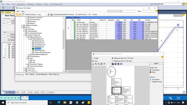
- D 04 (Length: 06 min, Update: Nov 13, 2021): Explain a case study XRIO file
- D 05 (Length: 10 min, Update: Nov 13, 2021): Modify a case study XRIO file
- D 06 (Length: 09 min, Update: Nov 13, 2021): Modify the XRIO template, RIO blocks
Part E: Impedance Protection Functions
- E 01 (Length: 09 min, Update: Nov 26, 2021): Distance RIO block
- E 02 (Length: 07 min, Update: Nov 26, 2021): Advance Distance Test Module settings
- E 03 (Length: 08 min, Update: Nov 26, 2021): Distance protection function principal, Impedance View
- E 04 (Length: 18 min, Update: Nov 26, 2021): Analysis of several faults visually in the impedance view
- E 05 (Length: 19 min, Update: Nov 26, 2021): Analysis of several distance relays (RAZOA, ABB REL670, SEL421, Siemens 7SA8x, MiCOM P442, NR PCS 931S, Protecta)
- E 06 (Length: 08 min, Update: Nov 26, 2021): Distance Test Module settings
- E 07 (Length: 12 min, Update: Nov 26, 2021): Preparing XRIO file for testing of impedance protection functions
Part F: Autoreclosure Function (ANSI 79)
- F 01 (Length: 04 min, Update: Dec 03, 2021): Autoreclosure Description, auto reclose process
- F 02 (Length: 05 min, Update: Dec 03, 2021): Autoreclosure settings, Autoreclose timing diagram
- F 03 (Length: 11 min, Update: Dec 03, 2021): Autoreclosure simulation
- F 04 (Length: 12 min, Update: Dec 03, 2021): Testing of AR in state sequencer
- F 05 (Length: 09 min, Update: Dec 03, 2021): Testing of AR in the Autorecoser test module
Part G: Voltage and Frequency Protection Functions (ANSI 27, ANS59, ANSI81O, 81U)
- G 01 (Length: 06 min, Update: Dec 08, 2021): Ramping test modules and testing the frequency functions
- G 02 (Length: 05 min, Update: Dec 08, 2021): Paulse ramping test module
- G 03 (Length: 06 min, Update: Dec 08, 2021): Continous ramp and step ramp
- G 04 (Length: 11 min, Update: Dec 08, 2021): How to test Over/Under voltage protection functions (59, 27)
Part H: Study functions, testing, and commission of SIPROTEC 7UT6
- H 01 (Length: 10 min, Update: Dec 20, 2021): SIPROTEC 7UT6 setting description and configuration
- H 02 (Length: 14 min, Update: Dec 20, 2021): How to test differential function in SIPROTEC 7UT6, No combined characteristic feature, Automate testing by creating SIEMENS 7UT XRIO file
- H 03 (Length: 18 min, Update: Jan 01, 2022): The procedure of testing transformer protection with Quick CMC
Part K: Study functions, testing, and commission of MiCOM P44x
- K 01 (Length: 19 min, Update: Oct 31, 2022): Hardware and function description of the MiCOM P441, P442 & P444
- K 02 (Length: 17 min, Update: Oct 31, 2022): MiCOM Relay connections, communication, and Wire connection test
- K 03 (Length: 05 min, Update: Nov 1, 2022): Distance protection parameters and testing
- K 04 (Length: 10 min, Update: Nov 1, 2022): Switch on to fault protection (SOTF) function parameters and testing
- …


- Introduction, Software Installation, and general settings
- Different types of test modules
- Impedance/Vector/report View, Display settings
- Test Object, Hardware Configuration
- RIO, XRIO, and PTL
- Control Center, How to create and modify XRIO/ PTL files
- Transient module, Advanced transplay
- RIO Function Over Current, Define Element Characteristic, Pick-Up/ Drop-Off Test
- Testing of the Overcurrent and Directional Overcurrent Functions (67, 67N, 50, 51, 50N, 51N)
- Distance Configuration, Settings, Shot Test, Check Test, Search Test, Z\t Diagram, Zone Settings
- Testing of the Distance function (21)
- Principle of Differential Protection, Operating Characteristic, Differential Configuration, Differential Operating Characteristic, Differential Trip Time, and Harmonic Restraint
- Testing of the Differential protection function (87, 87G, 87T)
- Testing of the Power swing function
- Autoreclosure, shot and times, unsuccessful / Successful Sequence
- Testing of the Autorecloser function
- Testing of the Fault location function
- Testing of the Over/Under frequency (81O/ 81U)
- Testing of the Over/Undervoltage (59, 27)
- Testing of the Pole-Slip function (78)
- Testing of the Loss of Excitation (40)
- Testing of the Negative Phase Sequence (46)
- Testing of the Overload (49)
- How to test the distance function if the distance module is deactivated in the test universe software
- How to test differential function if the differential module is deactivated in the test universe
- Practical sections with testing of the relays (ABB REG670, MiCOM P441, MiCOM P123, …)

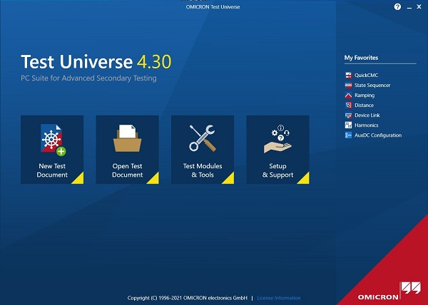
The testing & commissioning of the protection relays can be done by different testing software and hardware. In this training, we have used OMICRON Test Universe, Vebko AMpro, and FREJA win.
Impedance protection function testing is a critical process conducted to verify that the impedance relays or devices installed in a power system are functioning correctly and capable of accurately measuring and responding to changes in impedance levels. This testing involves injecting specific test signals into the relay, simulating various fault conditions, and comparing the relay’s response against expected outcomes to ensure its proper operation during actual fault scenarios. By rigorously testing the impedance protection function, power system operators can confirm the reliability and effectiveness of these protection schemes in safeguarding the electrical network against faults and maintaining system stability. Regular testing is essential to identify any potential issues or malfunctions that may compromise the protection system’s performance and integrity.
The Omicron CMC test kit is a versatile and reliable solution designed for testing various protection relay functions, including impedance, differential, overcurrent, and distance protection in power systems. This portable test kit offers a comprehensive range of testing capabilities, such as injecting signals, simulating fault conditions, and assessing relay responses, to ensure the accurate and effective operation of protection relays and related equipment. With its user-friendly interface, advanced functionalities, and high precision measurement capabilities, the Omicron CMC test kit is widely used by utilities, maintenance technicians, and protection engineers for testing and commissioning protection schemes, ensuring the reliability and performance of critical components in power systems.
The Omicron CMC test kit is a valuable tool for testing differential protection functions in power systems. By utilizing the test kit’s capabilities to inject specific test signals and simulate fault conditions, engineers can accurately assess the performance and reliability of the differential protection scheme. The advanced features and precise measurements offered by the Omicron CMC test kit enable users to verify that the protection relay operates correctly in detecting and isolating faults within the power system, ensuring the overall stability and protection of the electrical network. Conducting differential protection function testing with the Omicron CMC test kit helps to identify any potential issues, optimize the relay settings, and validate the effectiveness of the protection scheme in safeguarding the system against faults.
Need some experience people to join KBR-AMCDE, Oil and Gas, Al-Khobar, Saudi Arabia
About KBR-AMCDE
KBR-AMCDE is an entity formed to carry out general engineering and project management services under the Saudi Arabian Oil Company (Saudi Aramco) General Engineering Services Plus (GES+) initiative. KBR AMCDE provides front-end engineering and design (FEED), detailed design, procurement and project management services within the Oil & Gas industry. KBR-AMCDE specializes in front-end engineering design (FEED), detailed design, material procurement, and project management services (PMS). With extensive resources and technology, we deliver quality engineering packages to clients in Kingdom and overseas.
If you are qualified and experienced in PSCAD, please contact Mr. Narayanan Sivakumar with the below details:
Linkedin profile: linkedin.com/in/narayanan-sivakumar-95b80515
Email ID: narayanansivakumar1985@gmail.com
- Trainer: Dr. Saeed Roostaee (Profile)
- Pre-recorded videos
- The demo is available based on the request
- Course creation 8 April 2023
- Last update: 10 June 2023
- Total hours: 6 hrs and 17 min till 10 June 2023
- The updates will be added for free and no expiration.
Chapter I: Transformer Introduction
- Course introduction and transformer history (13 min)
- Concepts of the Electric Power Transmission Transformers (10 min)
- How does a Transformer work part I (7 min)
- How does a Transformer work part II (4 min)
- Transformer Parts and Functions (28 min)
- Single-phase and three-phase transformers (2 min)
- Transformer shipping and installation (9 min)
- Large Transformer Transportation (1 min)
- Transformer Equivalent Circuit (5 min)
- Why do we need an equivalent circuit (5 min)
- The Series Components (8 min)
- The Shunt Components (6 min)
- The Internal Ideal Transformer (4 min)
- Simplifying the Transformer Equivalent Circuit Part I (6 min)
- Simplifying the Transformer Equivalent Circuit Part II (4 min)
- Simplifying the Transformer Equivalent Circuit Part III (6 min)
- Vector Group Connections (15 min)
Chapter II: Transformer Faults
- Power Transformer Faults (3 min)
- Top 10 Transformer Blasts and Short Circuits (15 min)
- Power Transformer Explosion Incidents & Reasons & Precautionary Measures (4 min)
- Winding & Terminal Failures (4 min)
- The Effect of Through Faults on Power Transformers (4 min)
- Tap Changer (OLTC) Failure (3 min)
- Transformer bushings How it works (1 min)
- High Voltage bushing Faults early Detection and bushing monitoring (36 min)
- Why is Online Transformer Bushing Monitoring So Important (3 min)
- Transform Miscellaneous Failures (3 min)
- Why do we need Transformer Protection? (2 min)
- How do we Protect Transformers? (9 min)
- GE Transformer Protection& Control IED (2 min)
- SEL 787 & ABB RET 670 (14 min)
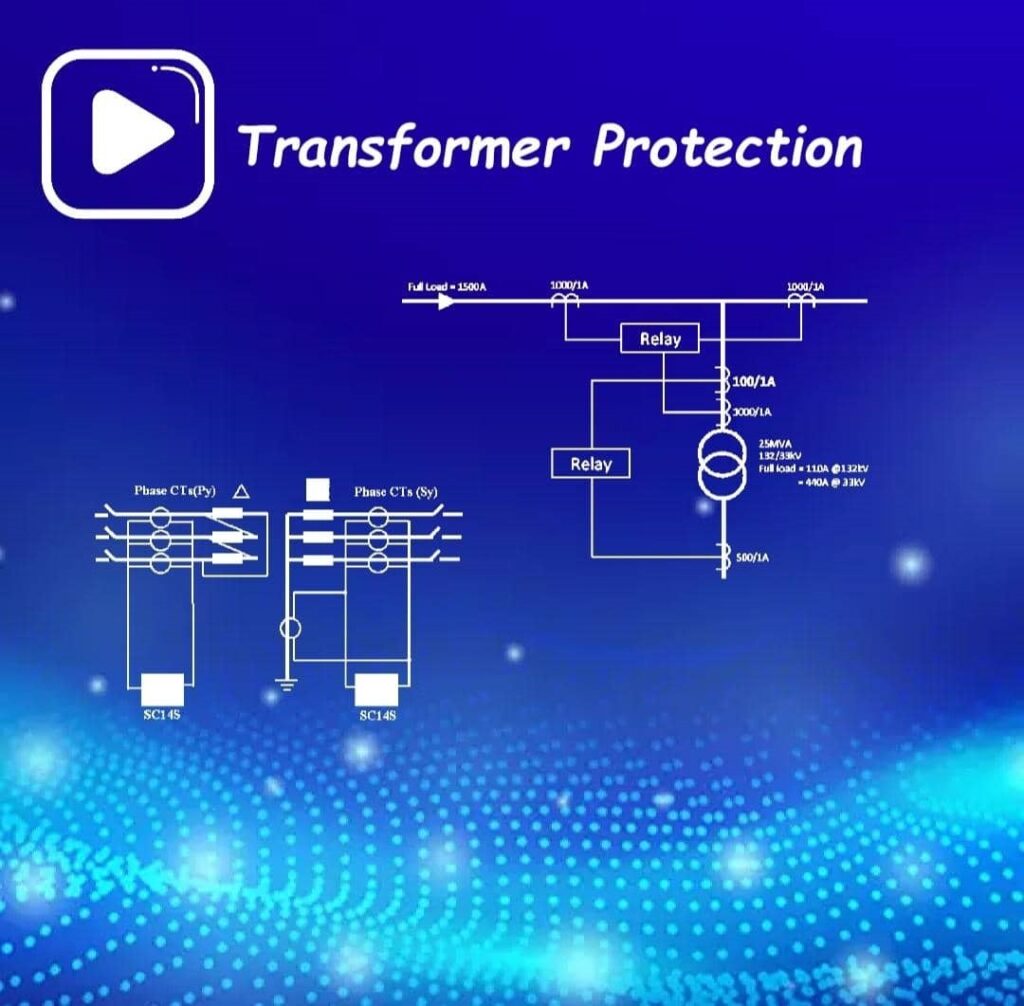
Chapter III: Transformer Protection Functions
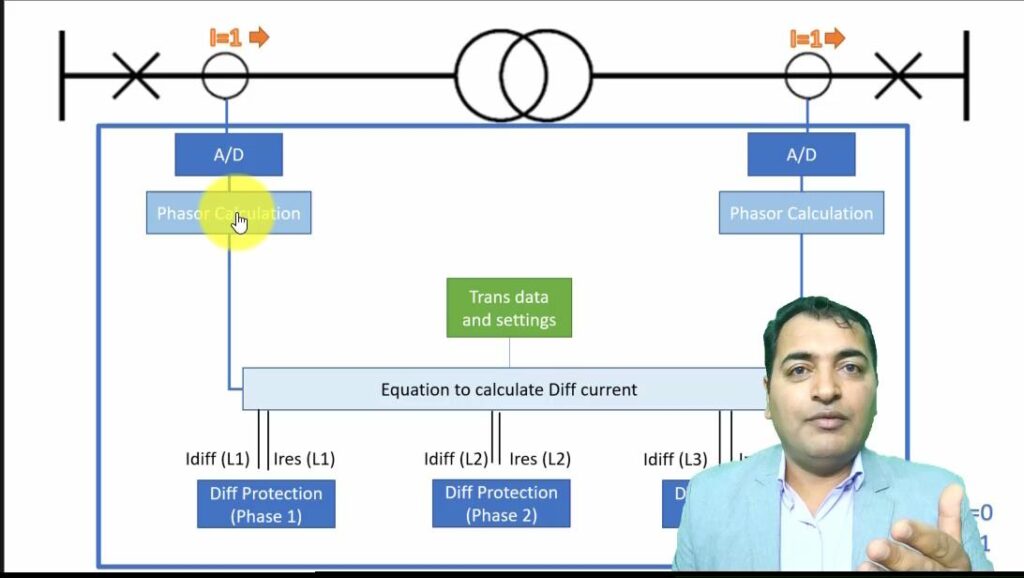
- Differential Protection Part I (16 min)
- Transformer Differential Protection Part II (14 min)
- Differences between digital transformer differential relays (7 min)
- Simulate different cases and test the differential transformer protection function (9 min)
- Restricted Earth Fault Protection(REF) in Transformer (7 min)
- High Impedance Restricted Earth Fault Protection working principle (7 min)
- Stability Resistance and Metrosil Resistance in REF Protection (12 min)
- Low impedance REF (8 min)
- Buchholz relay (4 min)
- Transformer Buchholz Protection Relay principal (2 min)
- Inside the Buchholz relay (4 min)
- Buchholz relay by MR (5 min)
Chapter IV: Transformer Protection Relay IEDS
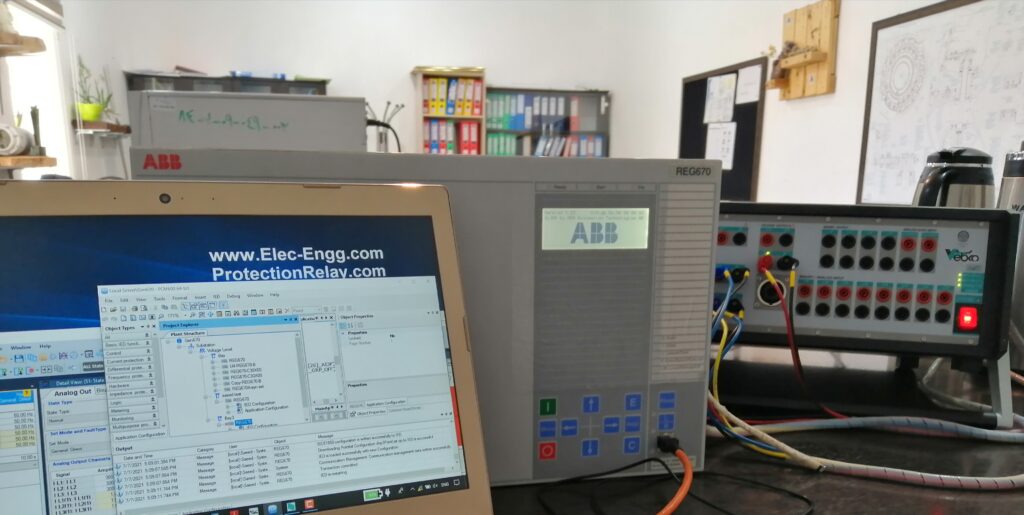
- ABB RET 670 Hardware structure (11 min)
- ABB RET 670 Transformer Protection Application template (6 min)
- ABB RET 670 Configuration and T2WPDIF Function block (12 min)
- ABB RET 670 Parameters and T2WPDIF parameters (11 min)
- Simulation of the differential protection algorithm in the ABB RET 670 relays (12 min)
SIEMENS 7UT85 configuration
How to enroll in this training course (How to access transformer protection training course):
1- Check out the Transformer Protection Training with the below link (https://elec-engg.com/product/transformer-protection-training/)
2- we will complete your order by sending your license to access the videos (https://elec-engg.com/how-to-access-our-training-courses/)
ِDemo is available
Transformer Protection Training
- Trainer: Dr. Saeed Roostaee (Profile)
Course details and samples on: https://elec-engg.com/transformer-protection-training-video/
- Trainer: Dr. Saeed Roostaee (Profil…
€80
The ABB RET 670 is a numerical generator protection relay designed to provide comprehensive protection and control functions for generators in power plants and other industrial applications. The device offers a wide range of protection features, such as overcurrent, voltage, frequency, and differential protection, as well as advanced functions for grid synchronization and monitoring. With its high-speed processing capabilities and advanced communication options, the RET 670 ensures reliable and efficient protection of generators, helping to enhance system reliability and prevent equipment damage during fault conditions.
Restricted Earth Fault (REF) protection in transformers is a differential protection scheme that detects earth faults within the transformer windings by comparing the current entering and leaving the transformer. The system uses current transformers to measure and compare the current flow, and if an imbalance is detected, it indicates the presence of a fault within the transformer. REF protection is designed to provide fast and reliable detection of earth faults, enabling the disconnection of the transformer from the system to prevent damage and ensure the safety of personnel and equipment. This advanced protection scheme is essential for maintaining the integrity and operational efficiency of transformers in power systems.
Transformer Differential Protection is a crucial element in safeguarding transformers from internal faults. By comparing the current entering and exiting the transformer windings using current transformers, this protection scheme can detect any imbalance that signifies a fault. If a fault is detected, the system initiates a trip signal to isolate the transformer from the network, preventing further damage. Differential protection is vital for ensuring the operational integrity of transformers and enhancing system reliability by swiftly isolating faults and minimizing downtime. It plays a critical role in maintaining the performance and longevity of transformer assets in power systems.
The Siemens 7UT85 is a numerical transformer protection relay that offers advanced protection features for medium and high-voltage transformers. It is equipped with various protection functions such as differential, overcurrent, and restricted earth fault protection, ensuring reliable and comprehensive protection for transformers. The 7UT85 is designed to provide accurate fault detection and fast response times to safeguard transformers from internal faults, helping to maintain system reliability and operational efficiency. With its flexible configuration options and integrated communication capabilities, the Siemens 7UT85 is a versatile and effective solution for transformer protection in power systems.
The Buchholz relay is a protective device used in oil-filled electrical equipment, such as transformers and tap changers, to detect and respond to faults and abnormalities in the oil insulation system. This relay operates based on the principle of gas accumulation in the oil. When a fault occurs within the equipment, such as a partial discharge or overheating, gas is generated, leading to increased pressure in the oil. The Buchholz relay is triggered by this pressure build-up and sends a signal to isolate the equipment to prevent further damage. Additionally, the relay can provide early warning of developing faults, allowing for proactive maintenance to be carried out. Overall, the Buchholz relay serves as a critical component in ensuring the safety and reliability of oil-filled electrical equipment.

Overview
The IEC 61850 source code library allows a fast and cost-efficient implementation of the IEC 61850 protocols (MMS, GOOSE, Sampled Values) into devices and applications. The APIs are designed to be very easy to use. The basic library is written in C (C99 compliant to provide maximum portability). Due to its hardware and platform-independent design, it can quickly deploy on any platform.
C#.NET Component
The C# library allows the creation of a managed DLL component that can easily be deployed in .NET applications. It is a wrapper of the C library. It can be used to be integrated into GUI applications, SCADA systems …
- Compatible with .NET and Mono
- Runs on Windows, Linux, and other platforms supported by .NET and Mono
- Very easy-to-use API
- Support for MMS client/server
- Support for GOOSE/SV subscribers
Features Source Code Library
- Easy to use IEC 61850 oriented API
- MMS, GOOSE, and Sampled Measured Values (SMV)
- TLS support
- Support editions 1, 2, and 2.1 of the standards
- Configurable generation of server data models from SCL/CID file at runtime
- Peer-reviewed and secure source code
- C library (C99) with C and C#/.NET API
Source codes that you see in this package:
- MMS client/server, GOOSE (IEC 61850-8-1)
- Sampled Values (SV – IEC 61850-9-2)
- Support for buffered and unbuffered reports
- Online report control block configuration
- Data access service (get data, set data)
- online data model discovery and browsing
- all data set services (get values, set values, browse)
- dynamic data set services (create and delete)
- log service
- flexible API to connect custom databases
- comes with sqlite implementation
- MMS file services (browse, get the file, set file, delete/rename the file)
- download COMTRADE files
- upload firmware or configuration files
- Setting group handling
- Service tracking (v1.5)
- GOOSE and SV control block handling
- TLS support
Application That can create with this library:
- Communications in Substations (MMS/GOOSE/SV)
- Communications for Wind Power Plants (IEC 61400-25)
- Communications for Decentralized Energy Resources (DER – IEC 61850-420)
- Intelligent Electronic Devices (IED)
- Measurement Devices
- SCADA Systems
- Monitoring
- Test systems
Easy programming and development of Scada and Monitoring System for protection Relays and other devices that compatible with IEC 61850 Standard with this package

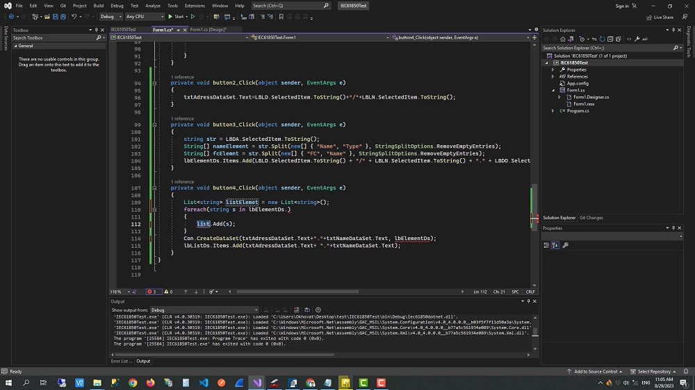
- IEC 61850 Programming with C#
- Pre-recorded sessions: 4 hours
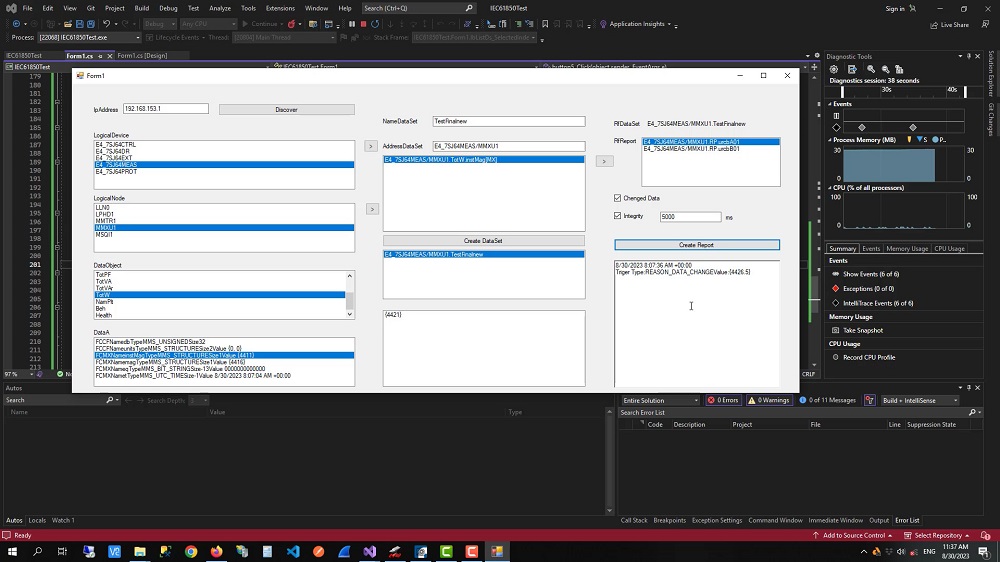
In this course, you will learn the principles of IEC 61850 programming and building monitoring and SCADA systems for networks that use IEC 61850 protection relays or IEDs (Intelligent Electronic Devices). To do so, first, you will learn about the IEC 61850 standard, including the concept of this standard, the simulation of the IEC 61850 GOOSE, and the IEC 61850 MMS reports. And how to read or write data and control commands to IEDs.
Next, you will learn Programming in IEC61850 Standard. In this chapter, you will learn how to use the IEC61850 Libraries for Programming in C# Language which are prepared by us and attached to the course as a gift. Then you will learn how to write a code for discovering and reading the substation IEDs, Functions, and Data Models. After that, you will learn how to write code to create DataSet and Report from the Data Models and set trigger options.
Course Content:
- Basics of IEC61850
- Sample Value
- GOOSE Protocol
- MMS Protocol
- Simulation of IEC 61850 Data Models
- Simulation of IEC 61850 DataSet
- Simulation of IEC 61850 GOOSE
- Simulation of IEC 61850 MMS
- Programming in IEC61850 Standard
- Necessary Libraries for Programming to C# Language in IEC61850 Standard
- Discovering Substation IEDs, Functions, and Data Models
- Read Data from Substation IEDs (Protection Relays,…)
- Create DataSet From Functions and Data Models and Read This DataSet
- Create a Report and Set Triggers
- Conclusion
Learn programming SCADA software based on IEC 61850 for your station as you like!
Supplementary Files:
- Source Code and Library for IEC 61850
- Visual Studio Code for Developers 2023
- C# Ultimate Guide – Beginner to Advanced
- FUNDAMENTALS OF COMPUTER PROGRAMMING WITH C#
- IEC 61850 Communication Networks and Systems In Substations: An Overview for Users
- Click here to download supplementary files
Source Code and Library for IEC 61850
The IEC 61850 source code library allows a fast and cost-efficient implementation of the IEC 61850 protocols (MMS, GOOSE, Sampled Values) into devices and applications. The APIs are designed to be very easy to use. The basic library is written in C (C99 compliant to provide maximum portability). Due to its hardware and platform-independent design, it can quickly deploy on any platform.
The C# library allows the creation of a managed DLL component that can easily be deployed in .NET applications. It is a wrapper of the C library. It can be used to be integrated into GUI applications, SCADA systems …
- Compatible with .NET and Mono
- Runs on Windows, Linux, and other platforms supported by .NET and Mono
- Very easy-to-use API
- Support for MMS client/server
- Support for GOOSE/SV subscribers

Features Source Code Library
- Easy to use IEC 61850 oriented API
- MMS, GOOSE, and Sampled Measured Values (SMV)
- TLS support
- Support editions 1, 2, and 2.1 of the standards
- Configurable generation of server data models from SCL/CID file at runtime
- Peer-reviewed and secure source code
- C library (C99) with C and C#/.NET API
Source codes that you see in this package:
- MMS client/server, GOOSE (IEC 61850-8-1)
- Sampled Values (SV – IEC 61850-9-2)
- Support for buffered and unbuffered reports
- Online report control block configuration
- Data access service (get data, set data)
- online data model discovery and browsing
- all data set services (get values, set values, browse)
- dynamic data set services (create and delete)
- log service
- flexible API to connect custom databases
- comes with sqlite implementation
- MMS file services (browse, get the file, set file, delete/rename the file)
- download COMTRADE files
- upload firmware or configuration files
- Setting group handling
- Service tracking (v1.5)
- GOOSE and SV control block handling
- TLS support
Application that can be created with this library:
- Communications in Substations (MMS/GOOSE/SV)
- Communications for Wind Power Plants (IEC 61400-25)
- Communications for Decentralized Energy Resources (DER – IEC 61850-420)
- Intelligent Electronic Devices (IED)
- Measurement Devices
- SCADA Systems
- Monitoring
- Test systems
Easy programming and development of Scada and Monitoring System for protection Relays and other devices that compatible with IEC 61850 Standard with this package
Keywords:
- IEC61850 Standard Communication Protocol Fundamentals
- IEC61850 Standard Standard Communication Protocols Simulation
- Programming for IEC61850 Standard Protocols
- Detect, Read, and Write values on IEDs (Relay Protections, Power Management, Meterings,…)
- IEC 61850 Programming
- IEC 61850 C# Programming in Visual Studio
- IEC 61850 SCADA Programming
- IEC 61850 MMS Programming
Reference Publication Type Title Value-added products Current Version
- IEC TS 61850-1-2: 2020 TS Part 1-2: Guideline on extending IEC61850 2020
- IEC TS 61850-1-2: 2020/AMD1:2022 TS Part 1-2: Guideline on extending IEC61850 Amendment 1 Consolidated Version 2022
- IEC TS 61850-2: 2019 TS Part 2: Glossary 2019
- IEC 61850-7-1: 2011/AMD 1: 2020 IS Part 7-1: Basic communication structure – Principles and models Amendment 1 Consolidated Version 2020
- IEC 61850-7-2: 2010/AMD 1:2020 IS Part 7-2: Basic information and communication structure – Abstract communication service interface(ASCI) Amendment 1 Consolidated Version 2020
- IEC 61850-7-3: 2010/AMD1:2020 IS Part 7-3: Basic communication structure – Common data classes Amendment 1 Consolidated Version 2020
- IEC 61850-7-4: 2010/ AMD 1: 2020 IS Part 7-4: Basic communication structure – Compatible logical node classes and data object classes Amendment 1 Consolidated Version 2020
- IEC TR 61850-7-5: 2021 TR Part 7-5: IEC 61850 modelling concepts 2021
- IEC TR 61850-7-6: 2019 TR Part 7-6: Guideline for definition of Basic Application Profiles (BAPs) using IEC61850 2019
- IEC TS 61850-7-7: 2018 TS Part 7-7: Machine processable format of IEC 61850-related data models for tools 2018
- IEC TS 61850-7-7: 2018/ AMD 1: 2023 TS Part 7-7: Machine processable format of IEC 61850-related data models for tools Amendment 1 Consolidated Version 2023
- IEC 61850-7-410: 2012 IS Part 7-410: Basic communication structure – Hydroelectric power plants – Communication for monitoring and control 2012
- IEC 61850-7-410: 2012/AMD 1: 2015 IS Part 7-410: Basic communication structure – Hydroelectric power plants – Communication for monitoring and control Amendment 1 Consolidated Version 2015
- IEC 61850-7-420: 2021 IS Part 7-420: Basic communication structure – Distributed energy resources and distribution automation logical nodes. 2021
- IEC TR 61850-7-500: 2017 TR Part 7-500: Basic information and communication structure – Use of logical nodes for modeling application functions and related concepts and guidelines for substations. 2017
- IEC TR 61850-7-510: 2021 TR Part 7-510: Basic communication structure – Hydroeletcric power plants, steam and gas turbines – Modelling concepts and guidelines. 2021
- IEC 61850-8-1: 2011/AMD1:2020 IS Part 8-1: Specific communication service mapping (SCSM) – Mappings to MMS (ISO 9506-1 and ISO 9506-2) and to ISO/IEC 8802-3 Amendment 1 Consolidated Version 2020
- IEC 61850-8-2:2018 IS Part 8-2: Specific communication service mapping (SCSM) – Mappings to extensive Messaging Presence Proptocol (XMPP). 2018
- IEC 61850-9-2: 2011/AMD1:2020 IS Part 9-2: Specific communication service mapping (SCSM) – Sampled values over ISO/IEC 8802-3 Amendment 1 Consolidated Version 2020
- IEC/IEEE 61850-9-3:2016 IS Part 9-3:Precision time protocol profile for power utility automation. 2016
- IEC 61850-10: 2012 IS Part 10: Conformance testing 2012
- IEC TR 61850-10-3:2022 TR Part 10-3: Functional testing of IEC 61850 systems. 2022
- IEC TS 61850-80-1:2016 TS Part 80-1: Guideline to exchanging information from a CDC-based data model; using IEC 60870-5-101 or IEC 60870-5-104 2016
- IEC TR 61850-80-3:2015 TR Part 80-3: Mapping to web protocols – Requirements and technical choices 2015
- IEC TS 61850-80-4:2016 TS Part 80-4: Translation from the COSEM object model (IEC 62056) TO the IEC 61850 data model 2016
- IEC TR 61850-90-1:2010 TR Part 90-1: Use of IEC 61850 for the communication between substations 2010
- IEC TR 61850-90-2:2016 TR Part 90-2: Using IEC 61850 for communication between substations and control centres 2016
- IEC TR 61850-90-3:2016 TR Part 90-3: Using IEC 61850 FOR condition monitoring diagnosis and analysis 2016
- IEC TR 61850-90-4:2020 TR Part 90-4: Network engineering guidelines 2020
- IEC TR 61850-90-5:2012 TR Part 90-4: Use of IEC 61850 to transmit synchrophasor information according to IEEE C37.118 2012
- IEC TR 61850-90-6:2018 TR Part 90-6: Use of IEC 61850 for Distribution Automation Systems 2018
- IEC TR 61850-90-7:2013 TR Part 90-7: Object models for power converters in dictributed energy resources (DER) systems. 2017
- IEC TR 61850-90-8:2016 TR Part 90-8: Object model for E-mobility 2016
- IEC TR 61850-90-9:2020 TR Part 90-9: Use of IEC 61850 for Electrical Energy Storage Systems 2020
- IEC TR 61850-90-10:2017 TR Part 90-10: Models for scheduling 2017
- IEC TR 61850-90-11:2020 TR Part 90-11: Methodologies for modelling of logics for IEC 61850 based applications 2020
- IEC TR 61850-90-12:2020 TR Part 90-12: Wide area network engineering guidelines 2020
- IEC TR 61850-90-13:2021 TR Part 90-13: Deterministic network technologies 2021
- IEC TR 61850-90-14:2021 TR Part 90-14: Using IEC 61850 FOR facts (flexible alternate current transmission systems), HVDC (high voltage direct current) transmission and power conversion data modelling 2021
- IEC TR 61850-90-16:2021 TR Part 90-16: Requirements of system management for Smart Energy Automation 2021
- IEC TR 61850-90-17:2017 TR Part 90-17: Using IEC 61850 to transmit power quality data. 2017
- Trainer: Dr. Saeed Roostaee (Profile)
- Face-to-face training
- Location & Fee: please contact us
- Duration: 10 days
Topics:
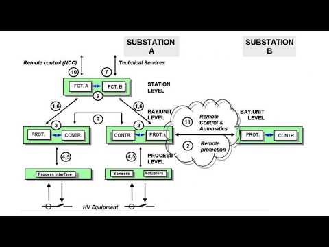
Substation Automation System:
- Substation Automation- Overview
- SAS Introduction
- SAS history
- SAS future
- Substation Automation Functions
- Process level
- Bay level
- Station Level
Network & Ethernet:
- Ethernet Concepts
- Fundamentals of Communication Via Ethernet
- Network Theory
- Components of the Network
- Fundamentals of Communication Via Ethernet Various Topologies
- Important Factors for Choosing a Topology
- Required Redundancy
- Distances Between Devices and Physical Dimensions of a Network
- Price Consideration
- Simple (Pure) Star
- Star Topology with Double Take
- Ring and Star Combination
- Economical Ring Solution With Only one External Switch
- Ring Topology With Two External Switches
- Commonly Used Configurations
- One Ring and Several Stars (most Frequently Occurring Topology)
- Two Rings Fitted into Each other
- Two Rings Connected Via a Double Main Ring
- Introduction: Provide an overview of SICAM PAS system
- Install SICAM PAS software and System components
- The new project, PAS Operation and Configure an IEC 103 interface
- How to use Device Descriptions (files)
- How to use the SICAM Value Viewer
- Configure an IEC 101 interface and T101 slave interfaces
- Configure an IEC 104 interface, T104 interface
- Introduction to IEC61850
- Creating a DIGIS database for a siprotec relay
- IEC61850 system configurator
- Data export and import
- Configure an IEC 61850 interface
- Normalization, Normalizing measured values
- Configure a PAS CC interface, Configuring an HMI interface
- Connect an IEC 61850 IED
IEC 61850:
- IEC 61850 Concepts
- An Introduction to IEC 61850
- IEC 61850 data structure and data format
- Information Modeling
- Interoperability
- Architecture: Station & Process Buses
- Logical Nodes
- ACSI – Class Models
- DataSet
- Communication models
- Controls
- GOOSE / GSSE
- Client / Server
- Data Reporting & Logging
- Sampled Values
- Time Synch
- GOOSE & Ethernet Frames
- 7-OSI Layers & Client / Server
- MMS Protocol
- ASN.1 Encoding & Message Parsing
- SCL Syntax and Semantics
- .ICD/.CID Files: IED definitions
- .SCD File: Substation Section
- Access Points & Communications
- EC 61850 station in DIGSI 5 and IEC 61850 System Configurator
- Time synchronization settings and SNTP configuration
- IEC 61850 configuration in DIGSI 4
- GOOSE configuration and the publisher/subscriber LNs
- GOOSE simulation via IEDScout
- Sample IEC61850 Configuration & Parameterization of a SIPROTEC 4 Device (BCU)
SIEMENS SAS
- Introduction to SICAM PAS Automation System
- Fields of Application
- Hardware Configuration
- Setting the Interface Parameters
- Setting for Time Synchronization
- Configuration of IEC 61850 Network
- Inter Bay Communication GOOSE
- Modbus Connection of Measuring Centers (EMA90)
- RS484 Bus Connection
- EMA90 Connection Setting
- Setting the Network Parameters for Ethernet Switches
- Configuration of General Parameters of Ethernet Switches
- Configuration of RSTP Bridge & RSTP Port Parameters
- Configuration of SNMP Users, Group, and Access
- 7XV6555 Serial/Ethernet Converter
- 7XV5655 Configuration Tool
- 7XV5655 Parameterization
- GPS Satellite Clock
- Server Type of Satellite Clock
- PCI Card type of Satellite Clock
- Station Level Engineering
- SICAM PAS Installation System Types
- Demo Version
- Licensed Version
- Installation Requirements
- SICAM PAS Configuration Working with Project Databases
- SICAM PAS UI-Operation
- SICAM PAS Value Viewer
- SICAM PASCC
- Introduction to SICAM PASCC Control Center
- Overview of SICAM PAS CC
- SICAM PASCC
- Starting The WinCC/PASCC Software
Practical Section
working with SIPROTEC 5 multifunction relay IED 7SX800
SICAM PAS stands for “Substation Automation System Process Automation Station,” which is a comprehensive solution for monitoring, controlling, and automating various processes in substations. It is designed to improve the efficiency, reliability, and safety of electrical substations by providing real-time data and advanced automation functionalities. Sicam PAS helps operators to manage and optimize their substation operations effectively, ultimately enhancing overall system performance.
SICAM PASCC is an advanced control center solution offered by Siemens for power utility operators. It provides real-time monitoring, control, and management capabilities for power grids and substations, helping operators make informed decisions and improve the overall reliability and efficiency of the electrical network. SICAM PASCC enables integration with various systems and devices, allowing for comprehensive centralized control and visualization of the grid operations. It plays a crucial role in ensuring smooth and secure power supply to customers by optimizing grid performance and response to fluctuations in demand or supply.
SICAM PAS UI-Operation is a user interface component of the Substation Automation System Process Automation Station (SICAM PAS) developed by Siemens. It provides operators with a graphical interface to monitor and control substation processes, enabling them to oversee system status, analyze data, and take necessary actions to ensure smooth operations. The UI-Operation module enhances operator efficiency by presenting relevant information in a user-friendly format, allowing for quick decision-making and effective management of substation activities.
WinCC and PASCC are both supervisory control and data acquisition (SCADA) software solutions developed by Siemens, but with different focuses and capabilities. WinCC is a general-purpose SCADA software that is widely used in various industries for monitoring and controlling processes, machinery, and equipment. It is versatile and highly customizable, with features for visualization, data logging, alarming, and historical trending. On the other hand, PASCC (Process Automation System Condition and Control) is specifically designed for the power utility sector, offering advanced functionalities tailored for monitoring, controlling, and managing power grid operations. PASCC provides specialized tools for real-time monitoring of substations, energy management, and grid optimization, making it a comprehensive solution for the unique requirements of power utilities. Ultimately, the choice between WinCC and PASCC would depend on the specific needs and industry focus of the user.
The SICAM PAS Value Viewer is a component of the SICAM PAS system developed by Siemens, designed to provide users with a comprehensive view of data values and parameters within the substation automation system. Through the Value Viewer, operators can access real-time information, historical data, and status updates to monitor and analyze the performance of the substation equipment. This tool enables users to make informed decisions, troubleshoot issues efficiently, and optimize the operation of the substation by leveraging the data visualization capabilities of SICAM PAS.

Information
- Course Name: SIPROTEC 5 and DIGSI 5 (advanced)
- Trainer: Dr. Saeed Roostaee
- Format: Pre-recorded videos (demo is available)
- Course creation: June 2023
- Last update: July 2023
Note: This course can also be held either Online or Face to face based on the request
Course Structure:
- Module 1: SIPROTEC 5 Hardware and ordering
- Module 2: Starting with DIGSI 5
- Module 3: Working with SIPROTEC 5 in online mode
- Module 4: System Functions
- Module 5: Function Groups
- Module 6: SIPROTEC 7SJ8
- Module 7: SIPROTEC 7SA8
- Module 8: SIPROTEC 7UT8
- Module 9: SIPROTEC 7SS8
- Module 10: SIPROTEC 7SK8
- Module 11: SIPROTEC 7VK8
- Module 12: SIPROTEC 7SD8
- Module 13: SIPROTEC 7SL8
- Module 14: SIPROTEC 7SX8
- Module 15: SIPROTEC 7UM8
- Module 16: SIPROTEC 7MD8
- Module 17: Functions and Settings
- Module 18: Signals and Masking IO
- Module 19: CFC
- Module 20: Control Functions
- Module 21: Display Page configuration
- Module 22: Functional Tests
- Module 23: Measured Values
- Module 24: Power Quality
- Module 25: Supervision
- Module 26: Communication
- Module 27: IEC 61850
- Module 28: Digital Twin
- Module 29: Case Study 7UT8
- Module 30: Case Study 7VK8
- Module 31: Case Study 7SA8
- Module 32: Case Study 7SS8
Course Details (Note: This part is continuously updating)
Module: SIPROTEC 5 Hardware and order
- SIPROTEC5 Hardware
- DIGSI 5 installation and DDD
- General Settings
- DIGSI 5 User interface
- New project + Add device (Offline)
- Modify the order code in the SIPROTEC online configurator
- SIPROTEC 5 Online Configurator
- Function Point
- SIP 5 Configuration Procedure
Module: Online & Working with SIPROTEC 5
- Connect to SIPROTEC 5
- Indications
- Fault Recording
- Log
- Reading Indications on the On-Site Operation Panel
- Reading Indications from the PC with DIGSI 5
- Displaying Indications
- Operational Log
- Fault Log
- Switching-Device Log
- Ground-Fault Log
- Setting-History Log
- User Log
- Security Log
- Device-Diagnosis Log
- Communication Log
- Communication-Supervision Log
- Motor-Starting Log
- Saving and Deleting the Logs
- Spontaneous Indication Display in DIGSI 5
- Spontaneous Fault Display on the On-Site Operation Panel
- Stored Indications in the SIPROTEC 5 Device
- Resetting Stored Indications of the Function Group
- Test Mode and Influence of Indications on Substation Automation Technology
- Changing the Transformation Ratios of the Transformer on the Device
Module: System Functions
- Sampling-Frequency Tracking and Frequency Tracking Groups
- Text Structure and Reference Number for Settings and Indications
- Processing Quality Attributes
- Protection Communication
- Date and Time Synchronization
- User-Defined Objects
- Device Settings
- Data Types
- Function Control
- Connection Examples
- Chatter blocking
- Settings-Group Switching
Module: Function Groups
- Voltage current 3-Phase
- Circuit-breaker
- Process Monitor
- Voltage-current 1-phase
- Motor
- Line
- Voltage 3-Phase
- Analog Units
- User-Defined Function Group
- Recording
- Motor Monitor
- Current-Flow Criterion
- Circuit-Breaker Condition for the Motor
- Closure Detection
- Motor-State Detection
- Cold-Load Pickup Detection
- Thermal Replica Rotor
- Capacitor Bank
Module: Functions and Settings
- Power-System Data
- Overcurrent Protection, Phases
- Overcurrent Protection, Ground
- Line Differential Protection
- Stub Differential Protection
- Restricted Ground-Fault Protection
- Distance Protection with Reactance Method (RMD)
- Distance Protection with Classic Method
- Impedance Protection
- Power-Swing Blocking
- Teleprotection with Distance Protection
- Universal Teleprotection with Distance Protection
- Ground-Fault Protection for High-Resistance Ground Faults in Grounded Systems
- Teleprotection with Ground-Fault Protection
- Universal Teleprotection with Ground-Fault Protection
- Echo and Tripping in the Event of Weak Infeed 874
- Tripping with Missing or Weak Infeed According to French Specification
- External Trip Initiation
- Automatic Reclosing Function
- Directional Overcurrent Protection, Phases
- Positive-Sequence Overcurrent Protection
- Instantaneous High-Current Tripping
- Group Indications of Overcurrent Protection Functions
- Overcurrent Protection, 1-Phase
- Voltage-Dependent Overcurrent Protection, Phases
- Sensitive Ground-Fault Detection
- Non-Directional Intermittent Ground-Fault Protection
- Directional Intermittent Ground-Fault Protection
- Negative-Sequence Protection
- Directional Negative-Sequence Protection with Current-Independent Time Delay
- Undercurrent Protection
- Overvoltage Protection with 3-Phase Voltage
- Overvoltage Protection with Positive-Sequence Voltage
- Overvoltage Protection with Negative-Sequence Voltage
- Overvoltage Protection with Positive-Sequence Voltage and Compounding
- Overvoltage Protection with Zero-Sequence Voltage/Residual Voltage
- Overvoltage Protection with Any Voltage
- Undervoltage Protection with 3-Phase Voltage
- Undervoltage Protection with Positive-Sequence Voltage
- Undervoltage Protection with Any Voltage
- Rate-of-Voltage-Change Protection
- Undervoltage-Controlled Reactive-Power Protection
- Voltage-Comparison Supervision
- Fault Locator
- Fault Locator Plus
- Over frequency Protection
- Under frequency Protection
- Rate of Frequency Change Protection
- Under frequency Load Shedding
- Phase-Sequence Switchover
- Instantaneous Tripping at Switch onto Fault
- Thermal Overload Protection, 3-Phase – Advanced
- Thermal Overload Protection, 1-Phase
- Temperature Supervision
- Circuit-Breaker Failure Protection
- Circuit-Breaker Restrike Protection
- Out-of-Step Protection
- Inrush-Current and 2nd Harmonic Detection
- Power Protection (P, Q), 3-Phase
- Current-Jump Detection
- Voltage-Jump Detection
- Vector-Jump Protection
- Arc Protection
- Voltage Measuring-Point Selection
Module: Specific Functions
- Current-Unbalance Protection for Capacitors, 1-Phase
- Peak Overvoltage Protection for Capacitors
- Motor-Starting Time Supervision
- Motor Restart Inhibit
- Load-Jam Protection Motor
- Thermal Overload Protection, Rotor
Module: Control Functions
- Introduction
- Switching Devices
- Switching Sequences
- Control Functionality
- Synchronization Function
- User-Defined Function Block [Control]
- CFC-Chart Settings
- Tap Changers
- Voltage Controller
- Point-on-Wave Switch
Module: Functional Tests
- Direction Test of the Phase Quantities
- Functional Test Protection Communication
- Functional Test of the Line Differential Protection
- Functional Test for Overvoltage Protection with Zero-Sequence Voltage/Displacement Voltage
- Primary and Secondary Tests of the Circuit-Breaker Failure Protection
- Circuit-Breaker Test
- Out-of-Step Protection Function Test
- Functional Test of the Inrush-Current Detection
- Functional Test of the Trip-Circuit Supervision
- Power-Swing Blocking Functional Test
- Functional Test for the Phase-Rotation Reversal
- Functional Test for Overvoltage Protection with Zero-Sequence Voltage/Residual Voltage
- Directional Testing for Isolated or Resonant-Grounded Systems
- Primary and Secondary Testing of the Synchronization Function
- Commissioning Hints for Voltage Control
Module: Measured Values
- Operational Measured Values
- Fundamental and Symmetrical Components
- THD and Harmonics
- Minimum/Maximum Values
- Average Values
- Energy Values
- Circuit-Breaker Monitoring
- Statistical Values of the Primary System
Module: Power Quality
- Voltage Variation
- Voltage Unbalance
- THD and Harmonics
- Total Demand Distortion
Module: Supervision
- Resource-Consumption Supervision
- Supervision of the Secondary System
- Supervision of the Device Hardware
- Supervision of Device Firmware
- Supervision of Hardware Configuration
- Supervision of Communication Connections
- Error Responses and Corrective Measures
- Group Indications
Module: IEC 61850
- External Signals
- Quality Processing/Affected by the User for Received GOOSE Values
- Quality Processing/Affected by the User in CFC Charts
- Quality Processing/Affected by the User in Internal Device Functions
More info and update about this course: Contac us
To participate in this face-to-face / online training course: contact us
- Course Name: Power System Protection based on SIEMENS and ABB relays
- Trainer: Dr. Saeed Roostaee
- Location: Turkey
- Duration: one week
- Course define: 14 July 2023
- Last update: 22 July 2023
- Course start: 5 November 2023
- Certificate: On successful completion of this training course, Elec-Engg Certificate will be awarded to the delegates
Day 1: Power system protection & Numerical Relay IEDs
- Why power system protection
- Numerical relay history
- Numerical structure
- Numerical relay functionality
- symmetrical component
- ANSI Codes
- Current and Voltage Transformer Types, Specifications, and Applications
- Protection Zones
- Time-current Characteristics Curves
- Modern Software for Protection
Day 2: SIPROTEC & DIGSI
- SIPROTEC 5 Hardware and ordering
- Connect to SIPROTEC 5
- Working with SIPROTEC 5 in online mode
- Indications and logs
- Recorder
- Relay configuration
- Functions and Settings
Day 3: ABB Relion & PCM 600
- ABB relays history
- PCM and connectivity pack installation
- Add IEDs
- Hardware configuration
- Application configuration
- Distance relay config
- Busbar relay config
Day 4: Feeder & Line Protection
- Overcurrent
- IDMT O/C & E/F Protection
- Definite Time (DT) Protection
- High-set Instantaneous Protection
- Earth fault
- Directional OC
- Distance
Day 5: Busbar and Circuit Breakers
- Circuit breaker failure protection (CBF)
- busbar arrangement
- busbar differential protection function
- Protection Zone
- REB670 series hardware structure
- REB670 Configuration
Day 6: Generator & Transformer Protection
- Transformer Introduction
- Vector Group Connections
- Transformer Faults
- Transformer Differential Protection
- Restricted Earth Fault Protection(REF)
- Buchholz Relay and Pressure Relief Operations
- ABB RET 670 Hardware structure
- ABB RET 670 Transformer Protection Application Template
- ABB RET 670 Configuration and Function blocks
- Generator construction
- Generator differential protection
- Generator stator earth fault protection
- Generator Under excitation / Loss-of -Excitation (ANSI 40 ) protection
- Generator Out-of-Step Protection (Pole Slip)
- Generator negative sequence protection
- Loss of Prime Mover protection
- Generator Over-Under frequency
- Generator under-voltage protection
- REG670 configuration

Sample DIGSI 5 logs
Library Global DIGSI 5 Library was opened
Project SaeedRoostaee_digsi5training opened
Analyzed compatibility information
6MU85 configuration requires 0 function points
Starting import of function chart(s) (CFC) from file C:\User
Importing log messages for function chart (CFC) Group warning,
Importing log messages for function chart (CFC) Process mode inactive,
Successfully finished importing
Analyzed software part.,7/27/2023,10:08:10 AM
Line Mode has no settings, so it is not listed under Settings. It is displayed in the Single-line configuration, Communication mapping, and Information routing.,7/27/2023,10:08:16 AM
DIGSI has no settings, so it is not listed under Settings. It is displayed in the Single-line configuration, Communication mapping, and Information routing.,7/27/2023,10:08:17 AM
Web UI has no settings, so it is not listed under Settings. It is displayed in the Single-line configuration, Communication mapping, and Information routing.
Analyzed compatibility information.,7/27/2023,10:09:11 AM
6MU85 configuration requires 0 function points.,7/27/2023,10:09:11 AM
6MU85 configuration requires 0 function points.,7/27/2023,10:09:11 AM
Starting import of function chart(s) (CFC) from file C:\Users\LENOVO\AppData\Local\Temp\3vawjx0o.yc3.tmp into device 6MU85.,7/27/2023,10:09:24 AM
Importing log messages for function chart (CFC) Group warning,7/27/2023,10:09:24 AM
Importing log messages for function chart (CFC) Process mode inactive,7/27/2023,10:09:24 AM
Successfully finished importing.,7/27/2023,10:09:24 AM
Analyzed software part.,7/27/2023,10:09:25 AM
Due to a change in hardware, 1 routing was deleted.,7/27/2023,10:09:28 AM
Line Mode has no settings, so it is not listed under Settings. It is displayed in the Single-line configuration, Communication mapping, and Information routing.,7/27/2023,10:09:32 AM
DIGSI has no settings, so it is not listed under Settings. It is displayed in the Single-line configuration, Communication mapping and Information routing.,7/27/2023,10:09:32 AM
Web UI has no settings, so it is not listed under Settings. It is displayed in the Single-line configuration, Communication mapping and Information routing.,7/27/2023,10:09:33 AM
Analyzed compatibility information.,7/27/2023,10:10:07 AM
6MU85 configuration requires 0 function points.
6MU85 configuration requires 0 function points.,7/27/2023,10:10:07 AM
Starting import of function chart(s) (CFC) from file C:\Users\LENOVO\AppData\Local\Temp\u2zboyex.sai.tmp into device 6MU85.,7/27/2023,10:10:21 AM
Importing log messages for function chart (CFC) Group warning,7/27/2023,10:10:21 AM
Importing log messages for function chart (CFC) Process mode inactive,7/27/2023,10:10:21 AM
Successfully finished importing.,7/27/2023,10:10:22 AM
6MU85 configuration requires 20 function points.,7/27/2023,10:10:22 AM
Analyzed software part.,7/27/2023,10:10:22 AM
Due to change in hardware, 1 routings were deleted.,7/27/2023,10:10:25 AM
Line Mode has no settings, so it is not listed under Settings. It is displayed in the Single-line configuration, Communication mapping and Information routing.,7/27/2023,10:10:29 AM
DIGSI has no settings, so it is not listed under Settings. It is displayed in the Single-line configuration, Communication mapping and Information routing.,7/27/2023,10:10:30 AM
Web UI has no settings, so it is not listed under Settings. It is displayed in the Single-line configuration, Communication mapping and Information routing.,7/27/2023,10:10:30 AM
Analyzed compatibility information.,7/27/2023,10:11:01 AM
6MU85 configuration requires 0 function points.,7/27/2023,10:11:01 AM
6MU85 configuration requires 0 function points.,7/27/2023,10:11:01 AM
Starting import of function chart(s) (CFC) from file C:\Users\LENOVO\AppData\Local\Temp\i5dxb3f4.p3z.tmp into device 6MU85.,7/27/2023,10:11:11 AM
Importing log messages for function chart (CFC) Group warning,7/27/2023,10:11:11 AM
Importing log messages for function chart (CFC) Process mode inactive,7/27/2023,10:11:11 AM
Successfully finished importing.,7/27/2023,10:11:11 AM
Analyzed software part.,7/27/2023,10:11:12 AM
Line Mode has no settings, so it is not listed under Settings. It is displayed in the Single-line configuration, Communication mapping and Information routing.,7/27/2023,10:11:17 AM
DIGSI has no settings, so it is not listed under Settings. It is displayed in the Single-line configuration, Communication mapping and Information routing.,7/27/2023,10:11:18 AM
Web UI has no settings, so it is not listed under Settings. It is displayed in the Single-line configuration, Communication mapping and Information routing.,7/27/2023,10:11:18 AM
Analyzed compatibility information.,7/27/2023,10:11:50 AM
6MU85 configuration requires 0 function points.,7/27/2023,10:11:50 AM
6MU85 configuration requires 0 function points.,7/27/2023,10:11:50 AM
Starting import of function chart(s) (CFC) from file C:\Users\LENOVO\AppData\Local\Temp\kd145sd3.5vv.tmp into device 6MU85.
Importing log messages for function chart (CFC) Group warning
Importing log messages for function chart (CFC) Process mode inactive,
Successfully finished importing.,7/27/2023,10:11:57 AM
Analyzed software part.
Line Mode has no settings, so it is not listed under Settings. It is displayed in the Single-line configuration, Communication mapping and Information routing.,7/27/2023,10:12:01 AM
DIGSI has no settings, so it is not listed under Settings. It is displayed in the Single-line configuration, Communication mapping and Information routing.,7/27/2023,10:12:02 AM
Web UI has no settings, so it is not listed under Settings. It is displayed in the Single-line configuration, Communication mapping and Information routing.,7/27/2023,10:12:02 AM
Function-chart (CFC) compilation,7/27/2023,10:13:01 AM
The project SaeedRoostaee_digsi5training was saved successfully.,7/27/2023,10:15:57 AM
Analyzed compatibility information.,7/27/2023,10:16:38 AM
7UM85 configuration requires 0 function points.,7/27/2023,10:16:38 AM
7UM85 configuration requires 0 function points.,7/27/2023,10:16:38 AM
Starting import of function chart(s) (CFC) from file C:\Users\LENOVO\AppData\Local\Temp\4fklxd5f.hx1.tmp into device 7UM85.,7/27/2023,10:16:59 AM
Analyzed software part.,7/27/2023,10:17:01 AM
Analyzed compatibility information.,7/27/2023,10:18:41 AM
7UM85 configuration requires 0 function points.,7/27/2023,10:18:41 AM
7UM85 configuration requires 0 function points.,7/27/2023,10:18:41 AM
Starting import of function chart(s) (CFC) from file C:\Users\LENOVO\AppData\Local\Temp\q1grapr5.1rp.tmp into device 7UM85.,7/27/2023,10:19:05 AM
Importing log messages for function chart (CFC) Group warning,7/27/2023,10:19:05 AM
Importing log messages for function chart (CFC) Process mode inactive,7/27/2023,10:19:05 AM
Successfully finished importing.,7/27/2023,10:19:05 AM
7UM85 configuration requires 85 function points.,7/27/2023,10:19:06 AM
Analyzed software part.,7/27/2023,10:19:06 AM
Analyzed compatibility information.,7/27/2023,10:20:28 AM
7UM85 configuration requires 0 function points.,7/27/2023,10:20:28 AM
7UM85 configuration requires 0 function points.,7/27/2023,10:20:28 AM
Starting import of function chart(s) (CFC) from file C:\Users\LENOVO\AppData\Local\Temp\1e0gnksz.mfz.tmp into device 7UM85.,7/27/2023,10:20:55 AM
Importing log messages for function chart (CFC) Group warning,7/27/2023,10:20:55 AM
Importing log messages for function chart (CFC) Process mode inactive,7/27/2023,10:20:55 AM
Successfully finished importing.,7/27/2023,10:20:55 AM
7UM85 configuration requires 105 function points.,7/27/2023,10:20:56 AM
Analyzed software part.,7/27/2023,10:20:56 AM
Analyzed compatibility information.,7/27/2023,10:21:48 AM
7UM85 configuration requires 0 function points.,7/27/2023,10:21:48 AM
7UM85 configuration requires 0 function points.,7/27/2023,10:21:48 AM
Starting import of function chart(s) (CFC) from file C:\Users\LENOVO\AppData\Local\Temp\yzrziyf1.5ct.tmp into device 7UM85.,7/27/2023,10:22:26 AM
Importing log messages for function chart (CFC) Group warning,7/27/2023,10:22:26 AM
Importing log messages for function chart (CFC) Process mode inactive,7/27/2023,10:22:26 AM
Successfully finished importing.,7/27/2023,10:22:26 AM
7UM85 configuration requires 330 function points.,7/27/2023,10:22:27 AM
Analyzed software part.,7/27/2023,10:22:29 AM
Analyzed compatibility information.,7/27/2023,10:23:24 AM
7UM85 configuration requires 0 function points.,7/27/2023,10:23:24 AM
7UM85 configuration requires 0 function points.,7/27/2023,10:23:24 AM
Starting import of function chart(s) (CFC) from file C:\Users\LENOVO\AppData\Local\Temp\g5ojtdjt.axj.tmp into device 7UM85.,7/27/2023,10:23:53 AM
Importing log messages for function chart (CFC) Group warning,7/27/2023,10:23:53 AM
Importing log messages for function chart (CFC) Process mode inactive,7/27/2023,10:23:54 AM
Successfully finished importing.,7/27/2023,10:23:54 AM
7UM85 configuration requires 255 function points.,7/27/2023,10:23:55 AM
Analyzed software part.,7/27/2023,10:23:55 AM
The project SaeedRoostaee_digsi5training was saved successfully.,7/27/2023,10:25:01 AM
Analyzed compatibility information.,7/27/2023,10:26:38 AM
7VU85 configuration requires 0 function points.,7/27/2023,10:26:38 AM
7VU85 configuration requires 0 function points.,7/27/2023,10:26:38 AM
Starting import of function chart(s) (CFC) from file C:\Users\LENOVO\AppData\Local\Temp\htzmdc0f.3i1.tmp into device 7VU85.,7/27/2023,10:26:56 AM
Importing log messages for function chart (CFC) Group warning,7/27/2023,10:26:56 AM
Importing log messages for function chart (CFC) Process mode inactive,7/27/2023,10:26:56 AM
Successfully finished importing.,7/27/2023,10:26:57 AM
Analyzed software part.,7/27/2023,10:26:57 AM
Analyzed compatibility information.,7/27/2023,10:27:59 AM
7VU85 configuration requires 0 function points.,7/27/2023,10:27:59 AM
7VU85 configuration requires 0 function points.,7/27/2023,10:27:59 AM
Starting import of function chart(s) (CFC) from file C:\Users\LENOVO\AppData\Local\Temp\djy2bv1q.rly.tmp into device 7VU85.,7/27/2023,10:28:29 AM
Importing log messages for function chart (CFC) Group warning,7/27/2023,10:28:29 AM
Importing log messages for function chart (CFC) Process mode inactive,7/27/2023,10:28:30 AM
Successfully finished importing.,7/27/2023,10:28:30 AM
7VU85 configuration requires 470 function points.,7/27/2023,10:28:31 AM
Analyzed software part.,7/27/2023,10:28:32 AM
Analyzed compatibility information.,7/27/2023,10:29:16 AM
7VU85 configuration requires 0 function points.,7/27/2023,10:29:16 AM
7VU85 configuration requires 0 function points.,7/27/2023,10:29:16 AM
Starting import of function chart(s) (CFC) from file C:\Users\LENOVO\AppData\Local\Temp\drdplp2d.gqq.tmp into device 7VU85.,7/27/2023,10:29:44 AM
Importing log messages for function chart (CFC) Group warning,7/27/2023,10:29:44 AM
Importing log messages for function chart (CFC) Process mode inactive,7/27/2023,10:29:45 AM
Successfully finished importing.,7/27/2023,10:29:45 AM
7VU85 configuration requires 400 function points.,7/27/2023,10:29:45 AM
Analyzed software part.,7/27/2023,10:29:46 AM
The project SaeedRoostaee_digsi5training was saved successfully.,7/27/2023,10:30:09 AM
The project SaeedRoostaee_digsi5training was saved successfully.,7/27/2023,10:30:47 AM
Analyzed compatibility information.,7/27/2023,10:32:33 AM
7VE85 configuration requires 0 function points.,7/27/2023,10:32:33 AM
7VE85 configuration requires 0 function points.,7/27/2023,10:32:33 AM
Starting import of function chart(s) (CFC) from file C:\Users\LENOVO\AppData\Local\Temp\4ynlrvko.squ.tmp into device 7VE85.,7/27/2023,10:32:46 AM
Importing log messages for function chart (CFC) Group warning,7/27/2023,10:32:46 AM
Importing log messages for function chart (CFC) Process mode inactive,7/27/2023,10:32:46 AM
Successfully finished importing.,7/27/2023,10:32:46 AM
Analyzed software part.,7/27/2023,10:32:47 AM
Analyzed compatibility information.,7/27/2023,10:33:33 AM
7VE85 configuration requires 0 function points.,7/27/2023,10:33:33 AM
7VE85 configuration requires 0 function points.,7/27/2023,10:33:33 AM
Starting import of function chart(s) (CFC) from file C:\Users\LENOVO\AppData\Local\Temp\h4jl3ijd.fox.tmp into device 7VE85.,7/27/2023,10:33:53 AM
Importing log messages for function chart (CFC) Group warning,7/27/2023,10:33:53 AM
Importing log messages for function chart (CFC) Process mode inactive,7/27/2023,10:33:54 AM
Successfully finished importing.,7/27/2023,10:33:54 AM
7VE85 configuration requires 75 function points.,7/27/2023,10:33:54 AM
Analyzed software part.,7/27/2023,10:33:55 AM
Analyzed compatibility information.,7/27/2023,10:34:28 AM
7VE85 configuration requires 0 function points.,7/27/2023,10:34:28 AM
7VE85 configuration requires 0 function points.,7/27/2023,10:34:28 AM
Starting import of function chart(s) (CFC) from file C:\Users\LENOVO\AppData\Local\Temp\rlvnzip1.5zo.tmp into device 7VE85.,7/27/2023,10:34:44 AM
Importing log messages for function chart (CFC) Group warning,7/27/2023,10:34:44 AM
Importing log messages for function chart (CFC) Process mode inactive,7/27/2023,10:34:45 AM
Successfully finished importing.,7/27/2023,10:34:45 AM
7VE85 configuration requires 115 function points.,7/27/2023,10:34:46 AM
Analyzed software part.,7/27/2023,10:34:47 AM
Analyzed compatibility information.,7/27/2023,10:35:58 AM
7VE85 configuration requires 0 function points.,7/27/2023,10:35:58 AM
7VE85 configuration requires 0 function points.,7/27/2023,10:35:58 AM
Starting import of function chart(s) (CFC) from file C:\Users\LENOVO\AppData\Local\Temp\d1etzmsn.mav.tmp into device 7VE85.,7/27/2023,10:36:15 AM
Importing log messages for function chart (CFC) Group warning,7/27/2023,10:36:15 AM
Importing log messages for function chart (CFC) Process mode inactive,7/27/2023,10:36:15 AM
Successfully finished importing.,7/27/2023,10:36:15 AM
7VE85 configuration requires 115 function points.,7/27/2023,10:36:16 AM
Analyzed software part.,7/27/2023,10:36:17 AM
Analyzed compatibility information.,7/27/2023,10:37:18 AM
7VE85 configuration requires 0 function points.,7/27/2023,10:37:18 AM
7VE85 configuration requires 0 function points.,7/27/2023,10:37:18 AM
Starting import of function chart(s) (CFC) from file C:\Users\LENOVO\AppData\Local\Temp\hysu15dy.clo.tmp into device 7VE85.,7/27/2023,10:37:41 AM
Importing log messages for function chart (CFC) Group warning,7/27/2023,10:37:41 AM
Importing log messages for function chart (CFC) Process mode inactive,7/27/2023,10:37:41 AM
Importing log messages for function chart (CFC) VoltageSelection,7/27/2023,10:37:41 AM
Successfully finished importing.,7/27/2023,10:37:42 AM
7VE85 configuration requires 115 function points.,7/27/2023,10:37:42 AM
Analyzed software part.,7/27/2023,10:37:42 AM
Analyzed compatibility information.,7/27/2023,10:38:47 AM
7VE85 configuration requires 0 function points.,7/27/2023,10:38:47 AM
7VE85 configuration requires 0 function points.,7/27/2023,10:38:47 AM
Starting import of function chart(s) (CFC) from file C:\Users\LENOVO\AppData\Local\Temp\c0jkcjzm.ff4.tmp into device 7VE85.,7/27/2023,10:39:13 AM
Importing log messages for function chart (CFC) Group warning,7/27/2023,10:39:13 AM
Importing log messages for function chart (CFC) Process mode inactive,7/27/2023,10:39:14 AM
Successfully finished importing.,7/27/2023,10:39:14 AM
7VE85 configuration requires 230 function points.,7/27/2023,10:39:14 AM
Analyzed software part.,7/27/2023,10:39:15 AM
Due to change in hardware, 15 routings were deleted.,7/27/2023,10:39:21 AM
The project SaeedRoostaee_digsi5training was saved successfully.,7/27/2023,10:40:17 AM
Analyzed compatibility information.,7/27/2023,10:42:05 AM
7SX85 configuration requires 0 function points.,7/27/2023,10:42:05 AM
7SX85 configuration requires 0 function points.,7/27/2023,10:42:05 AM
Starting import of function chart(s) (CFC) from file C:\Users\LENOVO\AppData\Local\Temp\rwtxsokr.dq5.tmp into device 7SX85.,7/27/2023,10:42:24 AM
7SX85 configuration requires 74 function points.,7/27/2023,10:42:25 AM
Analyzed software part.,7/27/2023,10:42:26 AM
Analyzed compatibility information.,7/27/2023,10:43:04 AM
7SX85 configuration requires 0 function points.,7/27/2023,10:43:04 AM
7SX85 configuration requires 0 function points.,7/27/2023,10:43:04 AM
Starting import of function chart(s) (CFC) from file C:\Users\LENOVO\AppData\Local\Temp\bhr4svo1.p0w.tmp into device 7SX85.,7/27/2023,10:43:27 AM
7SX85 configuration requires 126 function points.,7/27/2023,10:43:27 AM
Analyzed software part.,7/27/2023,10:43:28 AM
The project SaeedRoostaee_digsi5training was saved successfully.,7/27/2023,10:44:17 AM
Analyzed compatibility information.,7/27/2023,11:00:39 AM
6MD86 configuration requires 0 function points.,7/27/2023,11:00:39 AM
6MD86 configuration requires 0 function points.,7/27/2023,11:00:40 AM
Analyzed software part.,7/27/2023,11:00:46 AM
Analyzed compatibility information.,7/27/2023,11:01:09 AM
6MD86_1 configuration requires 0 function points.,7/27/2023,11:01:09 AM
6MD86_1 configuration requires 0 function points.,7/27/2023,11:01:09 AM
Starting import of function chart(s) (CFC) from file C:\Users\LENOVO\AppData\Local\Temp\oua4evsi.ttf.tmp into device 6MD86_1.,7/27/2023,11:01:28 AM
Analyzed software part.,7/27/2023,11:01:30 AM
Analyzed compatibility information.,7/27/2023,11:02:29 AM
6MD86 configuration requires 0 function points.,7/27/2023,11:02:29 AM
6MD86 configuration requires 0 function points.,7/27/2023,11:02:29 AM
Starting import of function chart(s) (CFC) from file C:\Users\LENOVO\AppData\Local\Temp\erexcpgi.y4l.tmp into device 6MD86.,7/27/2023,11:03:15 AM
Analyzed software part.,7/27/2023,11:03:20 AM
Due to change in hardware, 29 routings were deleted.,7/27/2023,11:03:32 AM
Analyzed compatibility information.,7/27/2023,11:04:08 AM
6MD86 configuration requires 0 function points.,7/27/2023,11:04:08 AM
6MD86 configuration requires 0 function points.,7/27/2023,11:04:08 AM
Starting import of function chart(s) (CFC) from file C:\Users\LENOVO\AppData\Local\Temp\vowhsuzk.axy.tmp into device 6MD86.,7/27/2023,11:04:48 AM
6MD86 configuration requires 60 function points.,7/27/2023,11:04:50 AM
Analyzed software part.,7/27/2023,11:04:51 AM
Due to change in hardware, 23 routings were deleted.,7/27/2023,11:05:00 AM
Analyzed compatibility information.,7/27/2023,11:06:19 AM
6MD86 configuration requires 0 function points.,7/27/2023,11:06:19 AM
6MD86 configuration requires 0 function points.,7/27/2023,11:06:19 AM
Starting import of function chart(s) (CFC) from file C:\Users\LENOVO\AppData\Local\Temp\wojcjuzy.cux.tmp into device 6MD86.,7/27/2023,11:06:36 AM
Importing log messages for function chart (CFC) GRPWARN_POW,7/27/2023,11:06:36 AM
Importing log messages for function chart (CFC) PROCESS_MODE_INACTIVE,7/27/2023,11:06:36 AM
Successfully finished importing.,7/27/2023,11:06:36 AM
6MD86 configuration requires 200 function points.,7/27/2023,11:06:37 AM
Analyzed software part.,7/27/2023,11:06:37 AM
Analyzed compatibility information.,7/27/2023,11:25:01 AM
7UT87 configuration requires 0 function points.,7/27/2023,11:25:01 AM
7UT87 configuration requires 0 function points.,7/27/2023,11:25:01 AM
Starting import of function chart(s) (CFC) from file C:\Users\LENOVO\AppData\Local\Temp\fk53a1ei.qb0.tmp into device 7UT87.,7/27/2023,11:25:20 AM
Importing log messages for function chart (CFC) Group warning,7/27/2023,11:25:20 AM
Importing log messages for function chart (CFC) Process mode inactive,7/27/2023,11:25:21 AM
Successfully finished importing.,7/27/2023,11:25:21 AM
Analyzed software part.,7/27/2023,11:25:22 AM
Analyzed compatibility information.,7/27/2023,11:26:30 AM
7UT87 configuration requires 0 function points.,7/27/2023,11:26:30 AM
7UT87 configuration requires 0 function points.,7/27/2023,11:26:30 AM
Starting import of function chart(s) (CFC) from file C:\Users\LENOVO\AppData\Local\Temp\4h5nmjbt.upq.tmp into device 7UT87.,7/27/2023,11:26:54 AM
Importing log messages for function chart (CFC) Group warning,7/27/2023,11:26:54 AM
Importing log messages for function chart (CFC) Process mode inactive,7/27/2023,11:26:54 AM
Successfully finished importing.,7/27/2023,11:26:55 AM
7UT87 configuration requires 25 function points.,7/27/2023,11:26:55 AM
Analyzed software part.,7/27/2023,11:26:56 AM
Analyzed compatibility information.,7/27/2023,11:28:30 AM
7UT87 configuration requires 0 function points.,7/27/2023,11:28:30 AM
7UT87 configuration requires 0 function points.,7/27/2023,11:28:30 AM
Starting import of function chart(s) (CFC) from file
SIPROTEC 5 and DIGSI 5 training by Dr. Saeed Roostaee
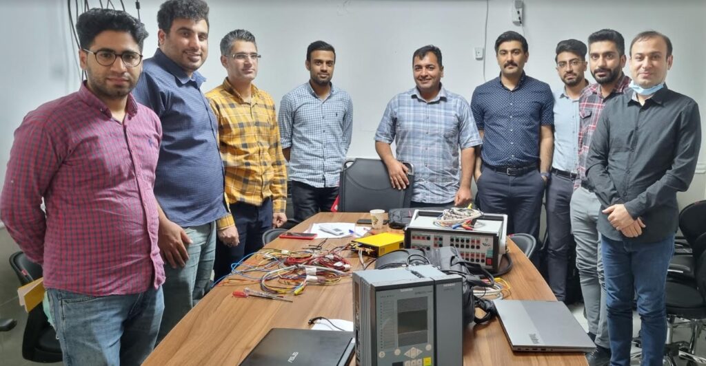
C:\Users\LENOVO\AppData\Local\Temp\zf1oyw44.fey.tmp into device 7UT87.,7/27/2023,11:28:58 AM
Importing log messages for function chart (CFC) Group warning,7/27/2023,11:28:58 AM
Importing log messages for function chart (CFC) Process mode inactive,7/27/2023,11:28:58 AM
Successfully finished importing.,7/27/2023,11:28:59 AM
7UT87 configuration requires 30 function points.,7/27/2023,11:28:59 AM
Analyzed software part.,7/27/2023,11:29:00 AM
Analyzed compatibility information.,7/27/2023,11:29:41 AM
7UT87 configuration requires 0 function points.,7/27/2023,11:29:42 AM
7UT87 configuration requires 0 function points.,7/27/2023,11:29:42 AM
Starting import of function chart(s) (CFC) from file C:\Users\LENOVO\AppData\Local\Temp\kocertsc.mb2.tmp into device 7UT87.,7/27/2023,11:30:10 AM
Importing log messages for function chart (CFC) Group warning,7/27/2023,11:30:10 AM
Importing log messages for function chart (CFC) Process mode inactive,7/27/2023,11:30:11 AM
Successfully finished importing.,7/27/2023,11:30:11 AM
7UT87 configuration requires 170 function points.,7/27/2023,11:30:11 AM
Analyzed software part.,7/27/2023,11:30:12 AM
Analyzed compatibility information.,7/27/2023,11:30:46 AM
7UT87 configuration requires 0 function points.,7/27/2023,11:30:46 AM
7UT87 configuration requires 0 function points.,7/27/2023,11:30:46 AM
Starting import of function chart(s) (CFC) from file C:\Users\LENOVO\AppData\Local\Temp\g1vz3iv4.n3x.tmp into device 7UT87.,7/27/2023,11:31:13 AM
Importing log messages for function chart (CFC) Group warning,7/27/2023,11:31:13 AM
Importing log messages for function chart (CFC) Process mode inactive,7/27/2023,11:31:13 AM
Successfully finished importing.,7/27/2023,11:31:13 AM
7UT87 configuration requires 50 function points.,7/27/2023,11:31:14 AM
Analyzed software part.,7/27/2023,11:31:14 AM
Analyzed compatibility information.,7/27/2023,11:31:47 AM
7UT87 configuration requires 0 function points.,7/27/2023,11:31:47 AM
7UT87 configuration requires 0 function points.,7/27/2023,11:31:47 AM
Starting import of function chart(s) (CFC) from file C:\Users\LENOVO\AppData\Local\Temp\mueys0vx.wkm.tmp into device 7UT87.,7/27/2023,11:32:14 AM
Importing log messages for function chart (CFC) Group warning,7/27/2023,11:32:14 AM
Importing log messages for function chart (CFC) Process mode inactive,7/27/2023,11:32:15 AM
Successfully finished importing.,7/27/2023,11:32:16 AM
Analyzed software part.,7/27/2023,11:32:17 AM
Analyzed compatibility information.,7/27/2023,11:33:01 AM
7UT87 configuration requires 0 function points.,7/27/2023,11:33:01 AM
7UT87 configuration requires 0 function points.,7/27/2023,11:33:01 AM
Starting import of function chart(s) (CFC) from file C:\Users\LENOVO\AppData\Local\Temp\o2l40wo1.1qd.tmp into device 7UT87.,7/27/2023,11:33:39 AM
Importing log messages for function chart (CFC) Group warning,7/27/2023,11:33:39 AM
Importing log messages for function chart (CFC) Process mode inactive,7/27/2023,11:33:40 AM
Successfully finished importing.,7/27/2023,11:33:40 AM
7UT87 configuration requires 45 function points.,7/27/2023,11:33:40 AM
Analyzed software part.,7/27/2023,11:33:41 AM
Analyzed compatibility information.,7/27/2023,11:34:32 AM
7UT87 configuration requires 0 function points.,7/27/2023,11:34:32 AM
7UT87 configuration requires 0 function points.,7/27/2023,11:34:32 AM
Starting import of function chart(s) (CFC) from file C:\Users\LENOVO\AppData\Local\Temp\bx5kvvoj.idx.tmp into device 7UT87.,7/27/2023,11:35:16 AM
Importing log messages for function chart (CFC) Group warning,7/27/2023,11:35:16 AM
Importing log messages for function chart (CFC) Process mode inactive,7/27/2023,11:35:16 AM
Importing log messages for function chart (CFC) DIS_Z4_trip_all_CB,7/27/2023,11:35:16 AM
Successfully finished importing.,7/27/2023,11:35:16 AM
7UT87 configuration requires 150 function points.,7/27/2023,11:35:17 AM
Analyzed software part.,7/27/2023,11:35:19 AM
Analyzed compatibility information.,7/27/2023,11:39:39 AM
7UT87 configuration requires 0 function points.,7/27/2023,11:39:39 AM
7UT87 configuration requires 0 function points.,7/27/2023,11:39:39 AM
Starting import of function chart(s) (CFC) from file C:\Users\LENOVO\AppData\Local\Temp\nwlj1jve.e4e.tmp into device 7UT87.,7/27/2023,11:40:12 AM
Importing log messages for function chart (CFC) Group warning,7/27/2023,11:40:12 AM
Importing log messages for function chart (CFC) Process mode inactive,7/27/2023,11:40:13 AM
Successfully finished importing.,7/27/2023,11:40:13 AM
7UT87 configuration requires 30 function points.,7/27/2023,11:40:13 AM
Analyzed software part.,7/27/2023,11:40:14 AM
Analyzed compatibility information.,7/27/2023,11:41:13 AM
7UT87 configuration requires 0 function points.,7/27/2023,11:41:13 AM
7UT87 configuration requires 0 function points.,7/27/2023,11:41:13 AM
Starting import of function chart(s) (CFC) from file C:\Users\LENOVO\AppData\Local\Temp\s20dfpoq.2kd.tmp into device 7UT87.,7/27/2023,11:41:59 AM
Importing log messages for function chart (CFC) Group warning,7/27/2023,11:41:59 AM
Importing log messages for function chart (CFC) Process mode inactive,7/27/2023,11:42:00 AM
Successfully finished importing.,7/27/2023,11:42:00 AM
7UT87 configuration requires 30 function points.,7/27/2023,11:42:01 AM
Analyzed software part.,7/27/2023,11:42:02 AM
Assignment of offline configuration 7UT87_3_2W 1.5 to another offline configuration 7UT87_1_2W basic is not possible. Assign always online devices to offline configurations.,7/27/2023,11:43:08 AM
The project SaeedRoostaee_digsi5training was saved successfully.,7/27/2023,11:43:56 AM
Analyzed compatibility information.,7/27/2023,11:45:51 AM
7SS85 configuration requires 0 function points.,7/27/2023,11:45:51 AM
7SS85 configuration requires 0 function points.,7/27/2023,11:45:51 AM
Starting import of function chart(s) (CFC) from file
C:\Users\LENOVO\AppData\Local\Temp\1lwlt0co.g3s.tmp into device 7SS85.,7/27/2023,11:46:01 AM
Importing log messages for function chart (CFC) Group warning,7/27/2023,11:46:01 AM
Importing log messages for function chart (CFC) Process mode inactive,7/27/2023,11:46:01 AM
Successfully finished importing.,7/27/2023,11:46:01 AM
Analyzed software part.,7/27/2023,11:46:01 AM
Analyzed compatibility information.,7/27/2023,11:46:52 AM
7VK87 configuration requires 0 function points.,7/27/2023,11:46:52 AM
7VK87 configuration requires 0 function points.,7/27/2023,11:46:52 AM
Starting import of function chart(s) (CFC) from file C:\Users\LENOVO\AppData\Local\Temp\gpn2w0ns.wbw.tmp into device 7VK87.,7/27/2023,11:47:13 AM
Importing log messages for function chart (CFC) Group warning,7/27/2023,11:47:13 AM
Importing log messages for function chart (CFC) Process mode inactive,7/27/2023,11:47:14 AM
Successfully finished importing.,7/27/2023,11:47:14 AM
Analyzed software part.,7/27/2023,11:47:15 AM
Analyzed compatibility information.,7/27/2023,11:48:11 AM
7SL87 configuration requires 0 function points.,7/27/2023,11:48:11 AM
7SL87 configuration requires 0 function points.,7/27/2023,11:48:11 AM
Starting import of function chart(s) (CFC) from file C:\Users\LENOVO\AppData\Local\Temp\by51qi0y.yx1.tmp into device 7SL87.,7/27/2023,11:48:32 AM
Importing log messages for function chart (CFC) Group warning,7/27/2023,11:48:32 AM
Importing log messages for function chart (CFC) Process mode inactive,7/27/2023,11:48:33 AM
Successfully finished importing.,7/27/2023,11:48:33 AM
Analyzed software part.,7/27/2023,11:48:34 AM
Analyzed compatibility information.,7/27/2023,11:49:10 AM
7SL87 configuration requires 0 function points.,7/27/2023,11:49:10 AM
7SL87 configuration requires 0 function points.,7/27/2023,11:49:10 AM
Starting import of function chart(s) (CFC) from file C:\Users\LENOVO\AppData\Local\Temp\ojyjebnh.0lh.tmp into device 7SL87.,7/27/2023,11:49:41 AM
Importing log messages for function chart (CFC) Group warning,7/27/2023,11:49:41 AM
Importing log messages for function chart (CFC) Process mode inactive,7/27/2023,11:49:42 AM
Successfully finished importing.,7/27/2023,11:49:42 AM
7SL87 configuration requires 225 function points.,7/27/2023,11:49:43 AM
Analyzed software part.,7/27/2023,11:49:44 AM
Analyzed compatibility information.,7/27/2023,11:50:19 AM
7SL87 configuration requires 0 function points.,7/27/2023,11:50:19 AM
7SL87 configuration requires 0 function points.,7/27/2023,11:50:20 AM
Starting import of function chart(s) (CFC) from file C:\Users\LENOVO\AppData\Local\Temp\znrrm0rx.ugj.tmp into device 7SL87.,7/27/2023,11:50:59 AM
Importing log messages for function chart (CFC) DISCON_7SL87_7SD87,7/27/2023,11:50:59 AM
Importing log messages for function chart (CFC) Group warning,7/27/2023,11:50:59 AM
Importing log messages for function chart (CFC) Process mode inactive,7/27/2023,11:51:00 AM
Importing log messages for function chart (CFC) RECL_7SX87_1,7/27/2023,11:51:00 AM
Importing log messages for function chart (CFC) RECL_7SX87_2,7/27/2023,11:51:00 AM
Successfully finished importing.,7/27/2023,11:51:01 AM
7SL87 configuration requires 400 function points.,7/27/2023,11:51:01 AM
Analyzed software part.,7/27/2023,11:51:03 AM
The project SaeedRoostaee_digsi5training was saved successfully.,7/27/2023,11:51:57 AM
Analyzed compatibility information.,7/27/2023,11:52:29 AM
7SD87 configuration requires 0 function points.,7/27/2023,11:52:29 AM
7SD87 configuration requires 0 function points.,7/27/2023,11:52:29 AM
Starting import of function chart(s) (CFC) from file C:\Users\LENOVO\AppData\Local\Temp\u2lbfpnj.14x.tmp into device 7SD87.,7/27/2023,11:52:49 AM
Importing log messages for function chart (CFC) Group warning,7/27/2023,11:52:49 AM
Importing log messages for function chart (CFC) Process mode inactive,7/27/2023,11:52:50 AM
Successfully finished importing.,7/27/2023,11:52:50 AM
Analyzed software part.,7/27/2023,11:52:51 AM
Analyzed compatibility information.,7/27/2023,11:53:34 AM
7SD87 configuration requires 0 function points.,7/27/2023,11:53:34 AM
7SD87 configuration requires 0 function points.,7/27/2023,11:53:34 AM
Starting import of function chart(s) (CFC) from file C:\Users\LENOVO\AppData\Local\Temp\ti4eq0z4.04y.tmp into device 7SD87.,7/27/2023,11:53:58 AM
Importing log messages for function chart (CFC) Group warning,7/27/2023,11:53:58 AM
Importing log messages for function chart (CFC) Process mode inactive,7/27/2023,11:53:59 AM
Successfully finished importing.,7/27/2023,11:53:59 AM
7SD87 configuration requires 170 function points.,7/27/2023,11:53:59 AM
Analyzed software part.,7/27/2023,11:54:00 AM
Analyzed compatibility information.,7/27/2023,11:54:43 AM
7SD87 configuration requires 0 function points.,7/27/2023,11:54:43 AM
7SD87 configuration requires 0 function points.,7/27/2023,11:54:43 AM
Starting import of function chart(s) (CFC) from file C:\Users\LENOVO\AppData\Local\Temp\qytlw5aa.tuf.tmp into device 7SD87.,7/27/2023,11:55:18 AM
Importing log messages for function chart (CFC) DISCON_7SL87_7SD87,7/27/2023,11:55:18 AM
Importing log messages for function chart (CFC) Group warning,7/27/2023,11:55:19 AM
Importing log messages for function chart (CFC) Process mode inactive,7/27/2023,11:55:20 AM
Importing log messages for function chart (CFC) RECL_7SX87_1,7/27/2023,11:55:20 AM
Importing log messages for function chart (CFC) RECL_7SX87_2,7/27/2023,11:55:20 AM
Successfully finished importing.,7/27/2023,11:55:21 AM
7SD87 configuration requires 345 function points.
Analyzed software part.,
The project SaeedRoostaee_digsi5training was saved successfully.


- Trainer: Dr. Saeed Roostaee (Profile)
- Online
- Date: 19 and 20 August 2023
- Platform: Google Meet & Online player
- Last update: 6 August 2023
- Contact us
Course content:
- Basics of Synchronous and Asynchronous Motors
- Motor Nameplate
- Motor Connections
- Motor Faults, Faults, and Protection Functions
- Overview of the Motor Protection Functions
- Motor Overcurrent Protection
- Motor Earth fault protection
- Motor Overload protection
- Motor Voltage protection
- Negative Sequence Protection
- Motor Lock Rotor & Mechanical Jam protection
- Motor Undercurrent protection
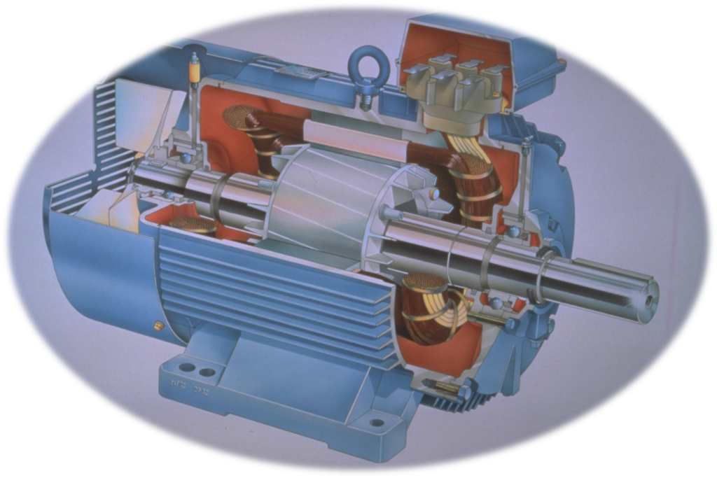
Modern numerical motor relay protection technology must be sufficient to meet the protection requirements of any of the vast range of motor designs. A motor protection relay providing sufficient protection will have the following set of characteristics such as extended start relay protection, loss-of-load relay protection, number of starts limitation, stalling relay protection, short circuit relay protection, thermal relay protection, Earth fault relay protection, negative sequence current detection, winding RTD measurement/trip, under-voltage relay protection, auxiliary supply supervision, …
- 14 Speed Switch
- 27 Undervoltage*
- 37 (P,C) Underpower/Undercurrent
- 38 Bearing Temperature*
- 46 Current Unbalance
- 47 Phase Reversal
- 49P PTC Overtemperature*
- 49R RTD Thermal*
- 49T Thermal Model
- 50 (P,G,Q) Overcurrent (Phase, Ground, Neg. Seq.)
- 50P LR Locked Rotor
- 50P LJ Load Jam
- 50N Neutral Overcurrent
- 51 (P,G,Q) Time-Overcurrent (Phase, Residual, Neg. Seq.)
- 55 Power Factor*
- 59P Phase Overvoltage*
- 60 Loss-of-Potential*
- 66 Starts-Per-Hour
- 81 (O,U) Over-/Underfrequency
- 87 Current Differential*
- 90 (P,I,T) Load Control (Power, Current, Thermal Capacity)
- 50/51 Adaptive Overcurrent
- 85 RIO SEL Mirrored Bits® Communications
- DFR Event Reports—Motor Starts, Motor Operating
- Statistics
- ENV Optional SEL-2600 RTD Module*
- HMI Operator Interface
- LDP Load Data Profiling
- LGC SELogic® Control Equations
- MET Metering
- RTU Remote Terminal Unit
- SDTM Slip-Dependent AccuTrackTM Thermal Model
- SER Sequential Events Recorders
- Stator overload protection 49
- Starting time supervision, locked rotor protection 48
- Restart inhibit 66,49R
- Negative-sequence current protection I2> 46
- Thermal unbalanced-load protection I2 2(t) 46
- Temperature measurement 1 38
- Undercurrent protection 37
- Active-power protection (P<) 32U
- Sensitive ground-fault protection 59N,
- non-directional 51Ns
- directional 67Ns
- Overcurrent protection 50, 51
- Current-differential protection 87
- Undervoltage protection 27
- Overvoltage protection 59
- Underexcitation protection 40
- Rotor ground-fault protection 64R
- Frequency protection 81
- Circuit-breaker failure protection 50BF
- User-programmable logic (CFC)
- Control functionality
- Graphic display (large)
- Flexible interfaces
- Frequency operating range (10 Hz – 70 Hz)
- Operational measured values and
- functional measured values
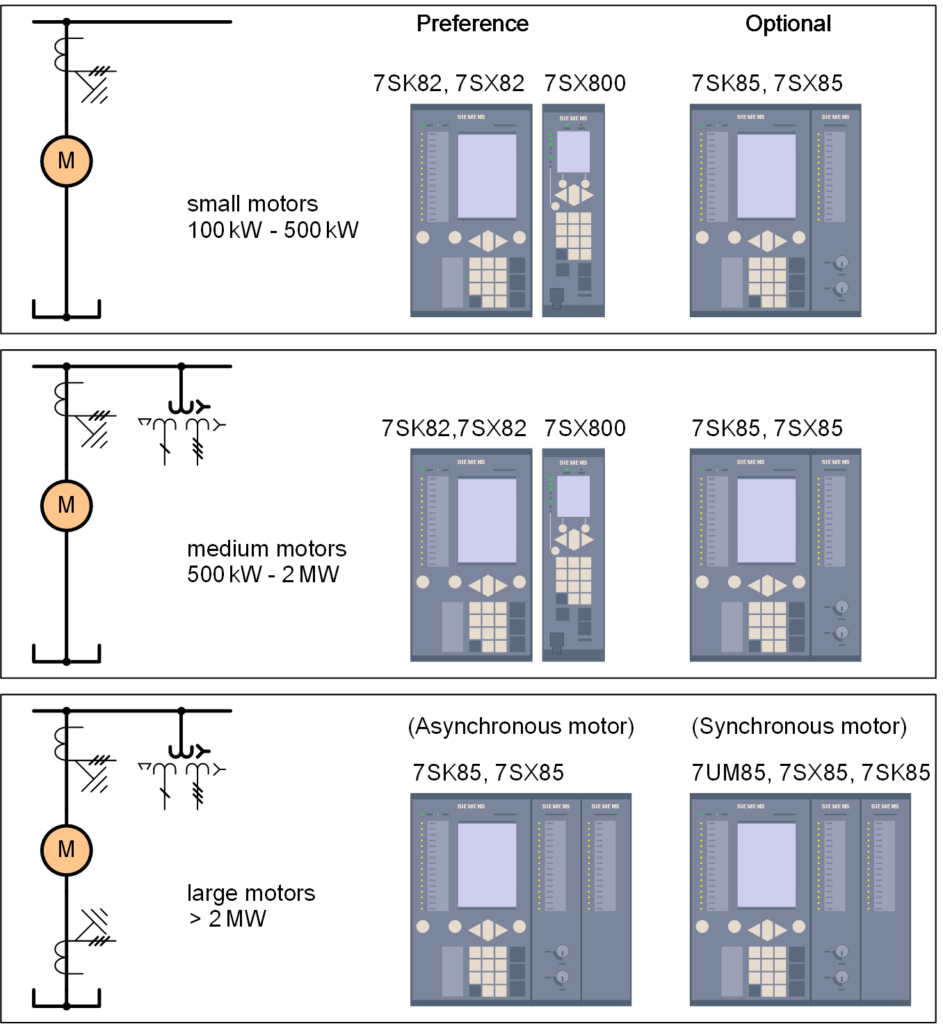
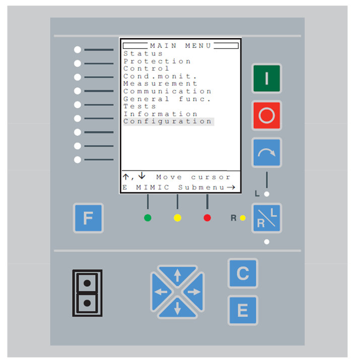
- Three-phase non-directional overcurrent protection, low-stage PHLPTOC 3I> 51P-1
- Three-phase non-directional overcurrent protection, instantaneous stage PHIPTOC 3I>>> 50P/51P
- Non-directional earth-fault protection, low-stage EFLPTOC I0> 51N-1
- Non-directional earth-fault protection, high stage EFHPTOC I0>> 51N-2
- Non-directional earth-fault protection, instantaneous stage EFIPTOC I0>>> 50N/51N
- Directional earth-fault protection, low stage DEFLPDEF I0> -> 67N-1
- Directional earth-fault protection, high stage DEFHPDEF I0>> -> 67N-2
- Rotor earth-fault protection MREFPTOC Io>R 64R
- Negative-sequence overcurrent protection for machines MNSPTOC I2>G/M 46G/46M
- Phase-reversal protection PREVPTOC I2>> 46R
- Three-phase thermal overload protection for motors MPTTR 3Ith>M 49M
- Motor startup supervision STTPMSU Is2t n< 48,66,14,51LR Motor load jam protection JAMPTOC Ist> 51LR
- Emergency start ESMGAPC ESTART ESTART
- Loss of load supervision LOFLPTUC 3I< 37 High-impedance or flux-balance based differential protection for machines MHZPDIF 3dIHi>G/M 87GH/87MH
- Stabilized differential protection for machines MPDIF 3dI>G/M 87G/87M
- Three-phase overvoltage protection PHPTOV 3U> 59
- Three-phase undervoltage protection PHPTUV 3U< 27 Positive-sequence overvoltage protection PSPTOV U1> 47O+
- Positive-sequence Undervoltage protection PSPTUV U1< 47U+ Negative-sequence overvoltage protection NSPTOV U2> 47OResidual
- overvoltage protection ROVPTOV U0> 59G
- Reverse power/directional overpower protection DOPPDPR P> 32R/32O
- Frequency gradient protection DAPFRC df/dt> 81R
- Over frequency protection DAPTOF f> 81O
- Under frequency protection DAPTUF f< 81U Three-phase underexcitation protection UEXPDIS X< 40 Circuit breaker failure protection CCBRBRF 3I>/I0>BF 51BF/51NBF
- Tripping logic TRPPTRC I -> O 94
- Multipurpose analog protection MAPGAPC MAP MAP
- Bay control QCCBAY CBAY CBAY
- Interlocking interface SCILO 3 3
- Circuit breaker/disconnector control GNRLCSWI I <-> O CB/DC I <-> O CB/DC
- Circuit breaker DAXCBR I <-> O CB I <-> O CB
- Disconnector DAXSWI I <-> O DC I <-> O DC
- Local/remote switch interface LOCREM R/L R/L
- Single point control (8 signals) SPC8GGIO
- Double point indication DPGGIO
- Single point indication SPGGIO
- Generic measured value MVGGIO
- Logic Rotating Switch for function selection and LHMI presentation SLGGIO
- Selector mini switch VSGGIO
- Pulse counter for energy metering PCGGIO
- Event counter CNTGGIO
- Supervision and monitoring
- Runtime counter for machines and devices MDSOPT OPTS OPTM
- Circuit breaker condition monitoring SSCBR CBCM CBCM
- Fuse failure supervision SEQRFUF FUSEF 60
- Current circuit supervision CCRDIF MCS 3I MCS 3I
- Trip-circuit supervision TCSSCBR TCS TCM
- Station battery supervision SPVNZBAT U<> U<>
- Energy monitoring EPDMMTR E E
- Measured value limit supervision MVEXP
- Three-phase current measurement CMMXU 3I 3I
- Three-phase voltage measurement (phase-to-earth)
- VPHMMXU 3Upe 3Upe
- Three-phase voltage measurement (phase-to-phase) VPPMMXU 3Upp 3Upp
- Residual current measurement RESCMMXU I0 I0
- Residual voltage measurement RESVMMXU U0 U0
- Power monitoring with P, Q, S, power factor, frequency PWRMMXU PQf PQf
- Sequence current measurement CSMSQI I1, I2 I1, I2
- Sequence voltage measurement VSMSQI U1, U2 V1, V2
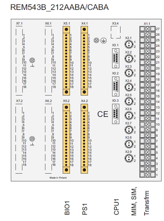
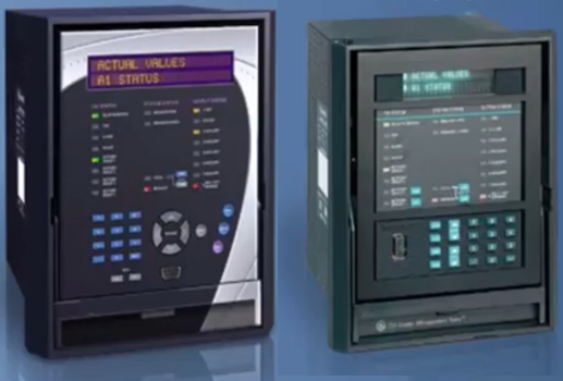
- Current Protection: Phase Overcurrent (67, 51, 50)
- Directional Control of Overcurrent Protection (67)
- Overcurrent Protection (50)
- Current Protection: Undercurrent (37)
- Phase Unbalance (46)
- Time Delayed Overcurrent Protection (51)
- Current Protection: Measured Earth Fault (50/51G)
- Directional Control of Measured Earth Fault Protection (67G)
- Measured Earth Fault Protection (50G)
- Time Delayed Measured Earth Fault Protection (51G)
- Current Protection: Derived Earth Fault (50/51N)
- Directional Control of Derived Earth Fault Protection (67N)
- Time Delayed Derived Earth Fault Protection (51N)
- High Impedance Restricted Earth Fault (87REF)
- Voltage Protection: NPS Overvoltage (47)
- Earth Fault Protection (50N)
- Voltage Protection: Under/Over Frequency (81)
- Power Protection – 32
- Sensitive Power Protection – 32S
- Break Capacity Limit (50BCL)
- Phase Reversal (46 PH REV)
- Temperature Monitoring
- CT Supervision (60CTS)
- Power Factor – 55
- Trip Circuit Supervision (74TCS)
- Close Circuit Supervision (74CCS)
- Circuit Breaker Failure (50BF)
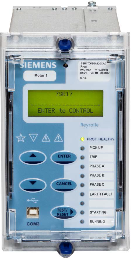

- Local human-machine interface
- 4 IED menu
- 4.2 Operation status ………………………………………………………………………………………………… 9
- 4.3 Query reports ………………………………………………………………………………………………….. 10
- 4.4 Set time …………………………………………………………………………………………………………… 10
- 4.5 Contrast …………………………………………………………………………………………………………… 10
- 4.6 Settings …………………………………………………………………………………………………………… 11
- 4.7 IED setting ………………………………………………………………………………………………………. 11
- 4.8 Test binary output ……………………………………………………………………………………………. 12
- 4.9 Testing operation …………………………………………………………………………………………….. 12
- 3.1.2 Terminals of Analogue Input Module (AIM) ……………………………………………….. 17
- 3.1.3 Terminals of Binary Input Module (BIM) ……………………………………………………. 18
- 3.1.4 Terminals of Binary Output Module (BOM) ……………………………………………….. 19
- 3.1.5 Terminals of Communication module (COM) ……………………………………………. 23
- 3.1.6 Communication ports of CPU module (CPU) ……………………………………………. 24
- 3.1.7 Terminals of Power Supply Module (PSM) ……………………………………………….. 25
- 3.1.8 RS232 port ……………………………………………………………………………………………….. 26
- 3.2 Connecting to Protective Earth…………………………………………………………………………. 26
- 3.3 Connecting the power supply module ……………………………………………………………… 26
- 3.4 Connecting to CT and VT circuits ……………………………………………………………………. 26
- 3.5 Connecting the binary inputs and outputs………………………………………………………… 26
- 3.6 Making the screen connection …………………………………………………………………………. 28
- 3.7 Optical connections …………………………………………………………………………………………. 28
- 3.8 RS485 and RS232 ports connection ……………………………………………………………….. 29
- 3.8.1 RS485 port connection …………………………………………………………………………….. 29
- 3.8.2 RS232 port connection …………………………………………………………………………….. 29
- 3.9 Connecting the GPS………………………………………………………………………………………… 30
- 4 Checking before energizing …………………………………………………………………………………………… 31
- Checking the power supply connection …………………………………………………………… 31
- 4.4 Checking the CT and VT circuits connection …………………………………………………… 31
- 4.4.1 Checking the CT circuits connection ………………………………………………………… 31
- 4.4.2 Checking the VT connection …………………………………………………………………….. 32
- 4.5 Checking the binary input and output connection ……………………………………………. 32
- 4.5.1 Checking the binary input connection ………………………………………………………. 32
- 4.5.2 Checking the binary output connection …………………………………………………….. 33
- 4.6 Checking the screened cables connection ………………………………………………………. 33
- 4.7 Checking the optical connections ……………………………………………………………………. 33
- 4.8 Checking the S485 and RS232 port connections ………………………………………………. 33
- 4.8.1 Checking the RS485 port connection ……………………………………………………….. 33
- 4.8.2 Checking RS232 port connection …………………………………………………………….. 33
- 4.9 Checking GPS connection ………………………………………………………………………………. 33
- 4.10 Checking the insulation voltage and insulation resistance ………………………………. 33
- 4.10.1 Checking the insulation voltage ……………………………………………………………….. 34
- 4.10.2 Checking the Insulation Resistance…………………………………………………………… 34
- 5 Checking after energizing ……………………………………………………………………………………………… 35
- 5.2 Test LCD …………………………………………………………………………………………………………. 35
- 5.3 Test the keyboard ……………………………………………………………………………………………. 35
- 5.4 Setting the IED time ………………………………………………………………………………………… 35
- 5.5 Self-supervision HMI data ……………………………………………………………………………….. 36
- 5.6 Checking the software and hardware version ………………………………………………….. 36
- Chapter 4 Read and change setting ………………………………………………………………………………… 37
- 1 Read and change the setting value ……………………………………………………………………………….. 38
- 1.1 Read and change the setting value via LHMI ………………………………………………….. 38
- 1.1.1 Introduction ………………………………………………………………………………………………. 38
- 1.1.2 Communication parameter ……………………………………………………………………….. 38
- 1.1.3 Equipment parameter ………………………………………………………………………………. 39
- 1.1.4 Setting values and binary settings for protection function …………………………. 39
- 2 Switching the setting group ……………………………………………………………………………………………. 46
- 2.1 Introduction ……………………………………………………………………………………………………… 46
- 2.2 Method for switching setting group via LHMI …………………………………………………… 46
- 2.3 Method for switching setting group via binary input …………………………………………. 46
- Chapter 5 Testing the communication connection and time synchronization ……………………. 47
- 1 Testing the communication connection ………………………………………………………………………….. 48
- 1.1 Testing the Ethernet communication ……………………………………………………………….. 48
- 1.1.1 Testing the electrical Ethernet communication …………………………………………. 48
- 1.1.2 Testing the optical Ethernet communication ……………………………………………… 48
- 1.2 Testing the RS485 port……………………………………………………………………………………. 48
- 1.3 Testing the RS232 port……………………………………………………………………………………. 48
- 2 Testing the time synchronization ……………………………………………………………………………………. 50
- 2.1 Network mode …………………………………………………………………………………………………. 50
- 2.2 Pulse mode ……………………………………………………………………………………………………… 50
- 2.3 IRIG-B mode ……………………………………………………………………………………………………. 50
- Chapter 6 IED testing ………………………………………………………………………………………………………. 51
- 1 Introduction ……………………………………………………………………………………………………………………. 52
- 2 Points for attention during testing…………………………………………………………………………………… 54
- 3 Preparing for test …………………………………………………………………………………………………………… 56
- 3.1 Introduction ……………………………………………………………………………………………………… 56
- 3.2 Connecting test equipment to IED …………………………………………………………………… 56
- 4 Testing the power supply ……………………………………………………………………………………………….. 58
- 4.1 Checking the self-startup performance ……………………………………………………………. 58
- 4.2 DC power on and power off testing………………………………………………………………….. 58
- 4.3 Checking the expiry date of power supply ……………………………………………………….. 58
- 5 Checking the analog channel ………………………………………………………………………………………… 59
- 5.1 Checking the zero drift …………………………………………………………………………………….. 59
- 5.2 Calibrating ……………………………………………………………………………………………………….. 59
- 5.3 Checking the accuracy and the linearity of analog quantitis …………………………….. 60
- 5.4 Checking the polarity of analog quantities ……………………………………………………….. 60
- 6 Testing binary input ……………………………………………………………………………………………………….. 62
- 7 Testing binary output ……………………………………………………………………………………………………… 63
- 8 Verifying the IED functions …………………………………………………………………………………………….. 64
- 8.1 Instantaneous differential protection ………………………………………………………………… 64
- 8.1.1 Verifying the settings ………………………………………………………………………………… 64
- 8.1.2 Completing the test ………………………………………………………………………………… 66
- 8.1.3 Reference setting list for test ……………………………………………………………………. 66
- 8.2 Percentage differential protection ……………………………………………………………………. 66
- 8.2.1 Verifying the settings ………………………………………………………………………………… 66
- 8.2.2 Completing the test ………………………………………………………………………………… 76
- 8.2.3 Reference setting list for test ……………………………………………………………………. 77
- 8.3 Restricted earth fault protection……………………………………………………………………….. 79
- 8.3.1 Verifying the settings ………………………………………………………………………………… 79
- 8.3.2 Completing the test ………………………………………………………………………………… 81
- 8.3.3 Reference setting list for test ……………………………………………………………………. 81
- 8.4 Overexcitation protection …………………………………………………………………………………. 83
- 8.4.1 Verifying the settings ………………………………………………………………………………… 83
- 8.4.2 Completing the test ………………………………………………………………………………… 88
- 8.4.3 Reference setting list for test ……………………………………………………………………. 88
- 8.5 Overcurrent protection …………………………………………………………………………………….. 90
- 8.5.1 Verifying the settings ………………………………………………………………………………… 90
- 8.5.2 Completing the test …………………………………………………………………………………… 97
- 8.5.3 Reference setting list for test ……………………………………………………………………. 97
- 8.6 Earth fault protection ……………………………………………………………………………………… 103
- 8.6.1 Verifying the settings ………………………………………………………………………………. 103
- 8.6.2 Completing the test …………………………………………………………………………………. 109
- 8.6.3 Reference setting list for test ………………………………………………………………….. 110
- 8.7 Neutral earth fault protection …………………………………………………………………………. 115
- 8.7.1 Verifying the settings ………………………………………………………………………………. 115
- 8.7.2 Completing the test ………………………………………………………………………………… 121
- 8.7.3 Reference setting list for test ………………………………………………………………….. 122
- 8.8 Thermal overload protection ………………………………………………………………………….. 127
- 8.8.1 Verifying the settings ………………………………………………………………………………. 127
- 8.8.2 Completing the test ………………………………………………………………………………… 137
- 8.8.3 Reference setting list for test ………………………………………………………………….. 137
- 8.9 Overload protection ……………………………………………………………………………………….. 138
- 8.9.1 Verifying the settings ………………………………………………………………………………. 138
- 8.9.2 Completing the test ………………………………………………………………………………… 142
- 8.9.3 Reference setting list for test ………………………………………………………………….. 142
- 8.10 Overvoltage protection ………………………………………………………………………………….. 144
- 8.10.1 Verifying the settings ………………………………………………………………………………. 144
- 8.10.2 Completing the test ………………………………………………………………………………… 150
- 8.10.3 Reference setting list for test ………………………………………………………………….. 150
- 8.11 Circuit breaker failure protection ……………………………………………………………………. 151
- 8.11.1 Verifying the settings ………………………………………………………………………………. 152
- 8.11.2 Completing the test ………………………………………………………………………………… 156
- 8.11.3 Reference setting list for test ………………………………………………………………….. 156
- 8.12 Dead zone protection …………………………………………………………………………………….. 158
- 8.12.1 Verifying the settings ………………………………………………………………………………. 158
- 8.12.2 Completing the test ………………………………………………………………………………… 161
- 8.12.3 Reference setting list for test ………………………………………………………………….. 161
- 8.13 STUB protection ……………………………………………………………………………………………. 161
- 8.13.1 Verifying the settings ………………………………………………………………………………. 162
- 8.13.2 Completing the test ………………………………………………………………………………… 164
- 8.13.3 Reference setting list for test ………………………………………………………………….. 164
- 8.14 Poles discordance protection ………………………………………………………………………… 164
- 8.14.1 Verifying the settings ………………………………………………………………………………. 165
- 8.14.2 Completing the test ………………………………………………………………………………… 169
- 8.14.3 Reference setting list for test ………………………………………………………………….. 169
- 8.15 Voltage transformer secondary circuit supervision ………………………………………… 170
- 8.15.1 Verifying the settings ………………………………………………………………………………. 170
- 8.15.2 Completing the test ………………………………………………………………………………… 181
- 8.15.3 Reference setting list for test ………………………………………………………………….. 181
- 9 Checking before operation …………………………………………………………………………………………… 183
- 9.1 Checking the LED …………………………………………………………………………………………. 183
- 9.2 Checking the display on LCD ………………………………………………………………………… 183
- 9.3 Checking the clock ………………………………………………………………………………………… 183
- 9.4 Checking the voltage and current ………………………………………………………………….. 183
- 9.5 Checking the setting group ……………………………………………………………………………. 183
- 9.6 Checking the setting ……………………………………………………………………………………… 183
- 9.7 Checking the binary input ………………………………………………………………………………. 184
- 9.8 Checking the normal operation mode …………………………………………………………….. 184
- 9.8.1 Trip and close test with the circuit breaker ………………………………………………. 184
- 9.9 Put into operation …………………………………………………………………………………………… 184
- Chapter 7 Operating maintenance …………………………………………………………………………………. 186
- 1 Attentions during operating ………………………………………………………………………………………….. 187
- 2 Routine checking …………………………………………………………………………………………………………. 189
- 3 Periodical checking ……………………………………………………………………………………………………… 190
- 4 Operation after updating software or replacing modules ………………………………………………. 191
- 4.1 Operation after updating software or replacing CPU module …………………………. 191
- 4.2 Operation after updating software or replacing communication module …………. 191
- 4.3 Operation after replacing the binary input or output module …………………………… 192
- 4.4 Operation after replacing the analog input module ………………………………………… 192
- 4.5 Operation after replacing power supply module …………………………………………….. 192
- 5 The alarm information and measure …………………………………………………………………………….. 193
- 5.1 Alarm information and the measure ……………………………………………………………….. 193
- Chapter 8 Transportation and storage ……………………………………………………………………………. 196
- 1 Transportion…………………………………………………………………………………………………………………. 197
- 2 Storage ………………………………………………………………………………………………………………………… 198
- Chapter 9 Appendix ……………………………………………………………………………………………………….. 200
- 1 Arrangement diagram of modules ………………………………………………………………………………… 201
- 2 Typical diagram ……………………………………………………………………………………………………………. 202
- Chapter 2 Basic protection elements ………………………………………………………………….. 9
- 1 Startup element ……………………………………………………………………………………………10
- 1.1 Introduction ……………………………………………………………………………………..10
- 1.2 Sudden-change current startup element ………………………………………………10
- 1.3 Differential current startup element ……………………………………………………..10
- 2 Input and output signals ……………………………………………………………………………….. 11
- 3 Settings ………………………………………………………………………………………………………13
- 4 Report ………………………………………………………………………………………………………..16
- Chapter 3 Differential protection ………………………………………………………………………..17
- 1 Introduction …………………………………………………………………………………………………18
- 2 Applications…………………………………………………………………………………………………18
- 3 Protection algorithm ……………………………………………………………………………………..19
- 3.1 Differential and restraint current calculation ………………………………………….20
- 3.2 Automatic Ratio compensation …………………………………………………………..22
- 3.3 Automatic Vector group and zero sequence current compensation …………..26
- 4 Protection principle……………………………………………………………………………………….32
- 4.1 Instantaneous differential protection characteristic …………………………………32
- 4.2 Treble slope percent differential protection characteristic ………………………..34
- 4.3 Selective inrush stabilization schemes …………………………………………………37
- 4.3.1 2nd harmonic stabilization …………………………………………………………………38
- 4.3.2 Fuzzy recognition of inrush based on the waveform ………………………………38
- 4.4 Overexcitation stabilization ………………………………………………………………..40
- 4.5 CT Failure supervision ………………………………………………………………………42
- 4.6 CT Saturation supervision ………………………………………………………………….43
- 4.7 Differential current supervision……………………………………………………………44
- 5 Input and output signals ………………………………………………………………………………..46
- 6 Settings ………………………………………………………………………………………………………47
- 7 Report ………………………………………………………………………………………………………..50
- 8 Technical data ……………………………………………………………………………………………..51
- Chapter 4 Restricted earth fault protection ………………………………………………………….53
- 1 Introduction …………………………………………………………………………………………………54
- 2 Applications…………………………………………………………………………………………………54
- 3 Protection principle……………………………………………………………………………………….56
- 3.1 Differential and restraint current calculation ………………………………………….57
- 3.2 Automatic Ratio compensation …………………………………………………………..59
- 3.3 Positive sequence current blocking ……………………………………………………..61
- 3.4 Restricted earth fault current alarm ……………………………………………………..62
- 4 Input and output signals ………………………………………………………………………………..63
- 5 Settings ………………………………………………………………………………………………………64
- 6 Report ………………………………………………………………………………………………………. 66
- 7 Technical data …………………………………………………………………………………………….. 67
- Chapter 5 Overexcitation protection ………………………………………………………………….. 69
- 1 Introduction ………………………………………………………………………………………………… 70
- 2 Protection principle ……………………………………………………………………………………… 70
- 2.1 Protection principle ………………………………………………………………………….. 70
- 2.2 Voltage channel configuration …………………………………………………………… 76
- 3 Input and output signals ……………………………………………………………………………….. 77
- 4 Settings …………………………………………………………………………………………………….. 78
- 5 Report ………………………………………………………………………………………………………. 79
- 6 Technical data …………………………………………………………………………………………….. 80
- Chapter 6 Overcurrent protection……………………………………………………………………… 83
- 1 Introduction ………………………………………………………………………………………………… 84
- 2 Protection principle ……………………………………………………………………………………… 84
- 2.1 Protection Elements ………………………………………………………………………… 84
- 2.2 Inrush Restraint Feature …………………………………………………………………… 86
- 2.3 Direction Determination Feature ………………………………………………………… 87
- 2.4 CBF initiation Feature ……………………………………………………………………… 90
- 3 Input and output signals ……………………………………………………………………………….. 91
- 4 Setting ………………………………………………………………………………………………………. 92
- 5 Report ………………………………………………………………………………………………………. 99
- 6 Technical data …………………………………………………………………………………………….. 99
- Chapter 7 Earth fault protection ……………………………………………………………………… 101
- 1 Protection principle ……………………………………………………………………………………. 102
- 1.1 Protection elements ………………………………………………………………………. 102
- 1.2 Inrush Restraint Feature …………………………………………………………………. 104
- 1.3 Direction Determination Feature ………………………………………………………. 105
- 1.4 CBF initiation Feature ……………………………………………………………………. 107
- 2 Input and output signals ……………………………………………………………………………… 108
- 3 Setting …………………………………………………………………………………………………….. 109
- 4 Report …………………………………………………………………………………………………….. 115
- 5 Technical data …………………………………………………………………………………………… 116
- Chapter 8 Neutral earth fault protection …………………………………………………………… 119
- 1 Protection principle ……………………………………………………………………………………. 120
- 1.1 Protection Elements ………………………………………………………………………. 120
- 1.2 Inrush Restraint Feature …………………………………………………………………. 122
- 1.3 Direction Determination Feature ………………………………………………………. 122
- 1.4 CBF initiation Feature ……………………………………………………………………. 124
- 2 Input and output signals ……………………………………………………………………………… 125
- 3 Setting …………………………………………………………………………………………………….. 126
- 4 Report …………………………………………………………………………………………………….. 132
- 5 Technical data …………………………………………………………………………………………… 133
- Chapter 9 Thermal overload protection ……………………………………………………………. 135
- 1 Introduction ………………………………………………………………………………………………. 136
- 2 Protection principle…………………………………………………………………………………….. 136
- 3 Input and output signals ……………………………………………………………………………… 138
- 4 Setting ……………………………………………………………………………………………………… 138
- 5 Report ……………………………………………………………………………………………………… 140
- 6 Technical data …………………………………………………………………………………………… 141
- Chapter 10 Overload protection ……………………………………………………………………….. 143
- 1 Protection principle…………………………………………………………………………………….. 144
- 2 Input and output signals ……………………………………………………………………………… 145
- 3 Setting ……………………………………………………………………………………………………… 146
- 4 Report ……………………………………………………………………………………………………… 148
- Chapter 11 Overvoltage protection ……………………………………………………………………. 149
- 5 Introduction ………………………………………………………………………………………………. 150
- 6 Protection principle…………………………………………………………………………………….. 150
- 6.1 Phase to phase overvoltage protection ……………………………………………… 150
- 6.2 Phase to earth overvlotage protection……………………………………………….. 151
- 7 Logic diagram …………………………………………………………………………………………… 151
- 8 Input and output signals ……………………………………………………………………………… 151
- 9 Setting ……………………………………………………………………………………………………… 152
- 10 Report ……………………………………………………………………………………………….. 154
- 11 Technical data …………………………………………………………………………………….. 154
- Chapter 12 Circuit breaker failure protection ………………………………………………………. 157
- 1 Introduction ………………………………………………………………………………………………. 158
- 2 Protection principle…………………………………………………………………………………….. 158
- 3 Logic diagram …………………………………………………………………………………………… 161
- 4 Input and output signals ……………………………………………………………………………… 163
- 5 Setting ……………………………………………………………………………………………………… 164
- 6 Report ……………………………………………………………………………………………………… 167
- 7 Technical data …………………………………………………………………………………………… 167
- Chapter 13 Dead zone protection ……………………………………………………………………… 169
- 1 Introduction ………………………………………………………………………………………………. 170
- 2 Protection principle…………………………………………………………………………………….. 170
- 2.1 Function description……………………………………………………………………….. 171
- 3 Logic diagram …………………………………………………………………………………………… 171
- 4 Input and output signals ……………………………………………………………………………… 172
- 5 Setting ……………………………………………………………………………………………………… 173
- 6 Report ……………………………………………………………………………………………………… 174
- 7 Technical data …………………………………………………………………………………………… 174
- Chapter 14 STUB protection ……………………………………………………………………………. 175
- 1 Introduction ………………………………………………………………………………………………. 176
- 2 Protection principle…………………………………………………………………………………….. 176
- 2.1 Function description……………………………………………………………………….. 176
- 3 Logic diagram …………………………………………………………………………………………… 177
- 4 Input and output signals ……………………………………………………………………………… 177
- 5 Setting ……………………………………………………………………………………………………… 178
- 6 Report …………………………………………………………………………………………………….. 180
- 7 Technical data …………………………………………………………………………………………… 181
- Chapter 15 Poles discordance protection ………………………………………………………….. 183
- 1 Introdcution ………………………………………………………………………………………………. 184
- 2 Protection principle ……………………………………………………………………………………. 184
- 2.1 Function description ………………………………………………………………………. 184
- 3 Logic diagram …………………………………………………………………………………………… 185
- 4 Input and output signals ……………………………………………………………………………… 186
- 5 Setting …………………………………………………………………………………………………….. 187
- 6 Report …………………………………………………………………………………………………….. 188
- 7 Technical data …………………………………………………………………………………………… 188
- Chapter 16 Secondary system supervision ………………………………………………………… 189
- 1 VT failure supervision function …………………………………………………………………….. 190
- 2 Function principle ……………………………………………………………………………………… 190
- 3 Input and output signals ……………………………………………………………………………… 193
- 4 Setting …………………………………………………………………………………………………….. 194
- 5 Report …………………………………………………………………………………………………….. 195
- 6 Technical data …………………………………………………………………………………………… 196
- Chapter 17 External BIs to trip BOs ………………………………………………………………….. 197
- 1 Introduction ………………………………………………………………………………………………. 198
- 2 Function principle ……………………………………………………………………………………… 198
- 3 BI Trigger Record ……………………………………………………………………………………… 199
- 4 BI Switch SetGroup …………………………………………………………………………………… 200
- 5 BI “Blk Rem Access” and “RELAY TEST” ………………………………………………………. 200
- 6 BI “BI_Config1~ BI_Config2” and “BI TRIGGER DR1~ 10” ………………………………. 201
- 7 Setting …………………………………………………………………………………………………….. 201
- Chapter 18 Station communication …………………………………………………………………… 203
- 1 Overview …………………………………………………………………………………………………. 204
- 1.1 Protocol ……………………………………………………………………………………….. 204
- 1.1.1 LON communication protocol ……………………………………………………. 204
- 1.1.2 IEC61850-8 communication protocol ………………………………………….. 204
- 1.1.3 IEC60870-5-103 communication protocol ……………………………………. 205
- 1.2 Communication port ………………………………………………………………………. 205
- 1.2.1 Front communication port …………………………………………………………. 205
- 1.2.2 RS485 communication ports ……………………………………………………… 205
- 1.2.3 Ethernet communication ports …………………………………………………… 205
- 1.3 Technical data ………………………………………………………………………………. 205
- Front communication port …………………………………………………………………………………. 206
- RS485 communication port ………………………………………………………………………………. 206
- 2 Typicalcommunication scheme ……………………………………………………………………. 208
- 2.1 Typical substation communication scheme ………………………………………… 208
- 2.2 Typical time synchronizing scheme ………………………………………………….. 208
- Chapter 19 Hardware …………………………………………………………………………………….. 211
- This chapter describes the IED hardware. …………………………………………………………… 211
- 3 Introduction ………………………………………………………………………………………………. 212
- 3.1 IED structure ………………………………………………………………………………… 212
- 3.2 IED appearance …………………………………………………………………………….. 212
- 3.3 IED module arrangement ………………………………………………………………… 213
- 3.4 The rear view of the protection IED …………………………………………………… 213
- 4 Local human-machine interface …………………………………………………………………… 214
- 4.1 Human machine interface ……………………………………………………………….. 214
- 4.2 LCD …………………………………………………………………………………………….. 215
- 4.3 Keypad ………………………………………………………………………………………… 215
- 4.4 Shortcut keys and functional keys …………………………………………………….. 216
- 4.5 LED …………………………………………………………………………………………….. 217
- 4.6 Front communication port ……………………………………………………………….. 218
- 5 Analog input module ………………………………………………………………………………….. 219
- 5.1 Introduction …………………………………………………………………………………… 219
- 5.2 Terminals of Analogue Input Module (AIM) ………………………………………… 219
- 5.3 Technical data ……………………………………………………………………………….. 220
- 5.3.1 Internal current transformer ……………………………………………………….. 220
- 5.3.2 Internal voltage transformer ………………………………………………………. 221
- 6 Communication module ……………………………………………………………………………… 222
- 6.1 Introduction …………………………………………………………………………………… 222
- 6.2 Substaion communication port …………………………………………………………. 222
- 6.2.1 RS232 communication ports ……………………………………………………… 222
- 6.2.2 RS485 communication ports ……………………………………………………… 222
- 6.2.3 Ethernet communication ports……………………………………………………. 222
- 6.2.4 Time synchronization port …………………………………………………………. 223
- 6.3 Terminals of Communication Module ………………………………………………… 223
- 6.4 Operating reports …………………………………………………………………………… 224
- 6.5 Technical data ……………………………………………………………………………….. 224
- 6.5.1 Front communication port …………………………………………………………. 224
- 6.5.2 RS485 communication port ……………………………………………………….. 225
- 6.5.3 Ethernet communication port …………………………………………………….. 225
- 6.5.4 Time synchronization ……………………………………………………………….. 226
- 7 Binary input module …………………………………………………………………………………… 227
- 7.1 Introduction …………………………………………………………………………………… 227
- 7.2 Terminals of Binary Input Module (BIM) …………………………………………….. 227
- 7.3 Technical data ……………………………………………………………………………….. 229
- 8 Binary output module …………………………………………………………………………………. 230
- 8.1 Introduction …………………………………………………………………………………… 230
- 8.2 Terminals of Binary Output Module (BOM) …………………………………………. 230
- 8.2.1 Binary Output Module A ……………………………………………………………. 230
- 8.2.2 Binary Output Module C ……………………………………………………………. 233
- 8.3 Technical data ……………………………………………………………………………….. 234
- 9 Power supply module …………………………………………………………………………………. 236
- 9.1 Introduction …………………………………………………………………………………… 236
- 9.2 Terminals of Power Supply Module (PSM) ………………………………………… 236
- 9.3 Technical data ………………………………………………………………………………. 238
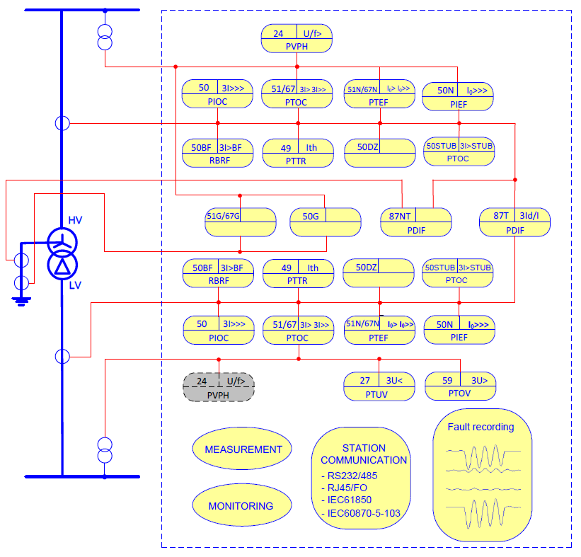
- 10 Techinical data ……………………………………………………………………………………. 239
- 10.1 Basic data ……………………………………………………………………………………. 239
- 10.1.1 Frequency ……………………………………………………………………………… 239
- 10.1.2 Internal current transformer ………………………………………………………. 239
- 10.1.3 Internal voltage transformer ………………………………………………………. 239
- 10.1.4 Auxiliary voltage ……………………………………………………………………… 239
- 10.1.5 Binary inputs…………………………………………………………………………… 240
- 10.1.6 Binary outputs ………………………………………………………………………… 240
- 10.2 Type tests …………………………………………………………………………………….. 241
- 10.2.1 Product safety-related Tests ……………………………………………………… 241
- 10.2.2 Electromagnetic immunity tests …………………………………………………. 242
- 10.2.3 DC voltage interruption test ………………………………………………………. 244
- 10.2.4 Electromagnetic emission test …………………………………………………… 244
- 10.2.5 Mechanical tests ……………………………………………………………………… 244
- 10.2.6 Climatic tests ………………………………………………………………………….. 245
- 10.2.7 CE Certificate …………………………………………………………………………. 246
- 10.3 IED design …………………………………………………………………………………… 246
- Chapter 20 Appendix ……………………………………………………………………………………… 247
- 1 General setting list …………………………………………………………………………………….. 248
- 1.1 Function setting list ……………………………………………………………………….. 248
- 1.2 Binary setting list …………………………………………………………………………… 266
- 2 General report list ……………………………………………………………………………………… 288
- 3 Time inverse characteristic …………………………………………………………………………. 295
- 3.1 11 kinds of IEC and ANSI inverse time characteristic curves ………………… 295
- 3.2 User defined characteristic ……………………………………………………………… 296
- 4 CT Requirement ……………………………………………………………………………………….. 296
- 4.1 Overview ……………………………………………………………………………………… 296
- 4.2 Current transformer classification …………………………………………………….. 296
- 4.3 Abbreviations (according to IEC 60044-1, -6, as defined) …………………….. 297
- 4.4 General current transformer requirements …………………………………………. 298
- 4.4.1 Protective checking current ………………………………………………………. 298
- 4.4.2 CT class ………………………………………………………………………………… 299
- 4.4.3 Accuracy class ……………………………………………………………………….. 301
- 4.4.4 Ratio of CT …………………………………………………………………………….. 301
- 4.4.5 Rated secondary current ………………………………………………………….. 301
- 4.4.6 Secondary burden …………………………………………………………………… 302
- 4.5 Rated equivalent secondary e.m.f requirements …………………………………. 302
- 4.5.1 Transformer differential protection ……………………………………………… 303

Line differential protection (87L):
The line differential protection consists of three protection functions, phase segregated differential protection function, sudden change current differential protection function and zero sequence current differential protection function.
These three functions are associated with achieving high sensitivity and reliability with capacitive charge current compensation and reliable phase selection during various system disturbances. The precise time
synchronization of sampling ensures the differential protection of both end IEDs to operate reliably
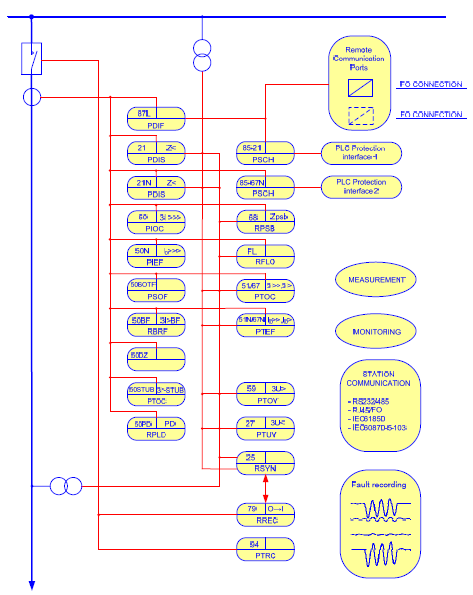
Distance protection (21, 21N)
The transmission line distance protection provides a five zones full scheme protection with all phase to phase faults and phase to earth fault loops independently for each zones.
Additionally, one extension zone is employed to co-operate with Auto-reclosing and tele-protection schemes.
Chapter 1 IED Introduction ………………………………………………………………………………………………… 1
Chapter 2 Local human machine interface ………………………………………………………………………… 3
1 Introduction ……………………………………………………………………………………………………………………… 4
2 Liquid crystal display(LCD) …………………………………………………………………………………………. 6
3 Keyboard ………………………………………………………………………………………………………………………… 7
4 IED menu ………………………………………………………………………………………………………………………… 8
4.1 Menu construction …………………………………………………………………………………………….. 8
4.2 Operation status ……………………………………………………………………………………………….. 9
4.3 Query reports ………………………………………………………………………………………………….. 10
4.4 Set time …………………………………………………………………………………………………………… 10
4.5 Contrast ………………………………………………………………………………………………………….. 10
4.6 Settings …………………………………………………………………………………………………………… 11
4.7 IED setting ………………………………………………………………………………………………………. 12
4.8 Test binary output ……………………………………………………………………………………………. 12
4.9 Testing operation …………………………………………………………………………………………….. 12
Chapter 3 Installing IED …………………………………………………………………………………………………… 13
1 Unpacking and checking the IED …………………………………………………………………………………… 14
2 Installing the IED …………………………………………………………………………………………………………… 15
3 IED connection ……………………………………………………………………………………………………………… 16
3.1 IED connector …………………………………………………………………………………………………. 16
3.1.1 Introduction ………………………………………………………………………………………………. 16
3.1.2 Terminals of Analogue Input Module (AIM) ………………………………………………. 17
3.1.3 Terminals of Binary Input Module (BIM) ……………………………………………………. 18
3.1.4 Terminals of Binary Output Module (AIM) …………………………………………………. 19
3.1.5 Terminals of Communication module (COM) ……………………………………………. 23
3.1.6 Communication ports of CPU module (CPU) ……………………………………………. 24
3.1.7 Terminals of Power Supply Module (PSM) ……………………………………………….. 25
3.1.8 RS232 port ………………………………………………………………………………………………. 26
3.2 Connecting to protective earth ………………………………………………………………………… 26
3.3 Connecting the power supply module ……………………………………………………………… 26
3.4 Connecting to CT and VT circuits ……………………………………………………………………. 26
3.5 Connecting the binary inputs and outputs ……………………………………………………….. 26
3.6 Making the screen connection …………………………………………………………………………. 28
3.7 Optical connections …………………………………………………………………………………………. 28
3.8 RS485 and RS232 ports connection ……………………………………………………………….. 29
3.8.1 RS485 port connection …………………………………………………………………………….. 29
3.8.2 RS232 port connection …………………………………………………………………………….. 29
3.9 Connecting the GPS ……………………………………………………………………………………….. 30
4 Checking before energizing …………………………………………………………………………………………… 31
4.1 Introduction ……………………………………………………………………………………………………… 31
4.2 Checking the protective earth connection ………………………………………………………… 31
4.3 Checking the power supply connection ……………………………………………………………. 31
4.4 Checking the CT and VT circuits connection …………………………………………………… 31
4.4.1 Checking the CT circuits connection ………………………………………………………… 31
4.4.2 Checking the VT connection …………………………………………………………………….. 32
4.5 Checking the binary input and output connection …………………………………………….. 32
4.5.1 Checking the binary input connection ……………………………………………………….. 32
4.5.2 Checking the binary output connection …………………………………………………….. 33
4.6 Checking the screened cables connection ………………………………………………………. 33
4.7 Checking the optical connections …………………………………………………………………….. 33
4.8 Checking the S485 and RS232 port connectios ………………………………………………. 33
4.8.1 Checking the RS485 port connection ……………………………………………………….. 33
4.8.2 Checking RS232 port connection ……………………………………………………………… 33
4.9 Checking GPS connection ………………………………………………………………………………. 33
4.10 Checking the insulation voltage and insulation resistance ……………………………….. 33
4.10.1 Checking the insulation voltage ………………………………………………………………… 34
4.10.2 Checking the insulation resistance …………………………………………………………… 34
5 Checking after energizing ………………………………………………………………………………………………. 35
5.1 Introduction ……………………………………………………………………………………………………… 35
5.2 Test LCD …………………………………………………………………………………………………………. 35
5.3 Test the keyboard ……………………………………………………………………………………………. 35
5.4 Setting the IED time ………………………………………………………………………………………… 35
5.5 Self-supervision HMI data ……………………………………………………………………………….. 36
5.6 Checking the software and hardware version ………………………………………………….. 36
Chapter 4 Read and change setting …………………………………………………………………………………. 37
1 Read and change the setting vaule ……………………………………………………………………………….. 38
1.1 Read and change the setting value via LHMI…………………………………………………… 38
1.1.1 Introduction ………………………………………………………………………………………………. 38
1.1.2 Communication parameter ……………………………………………………………………….. 38
1.1.3 Equipment parameter ……………………………………………………………………………….. 39
1.1.4 Setting values and binary settings for protection function …………………………. 39
2 Switching the setting group ……………………………………………………………………………………………. 48
2.1 Introduction ……………………………………………………………………………………………………… 48
2.2 Method for switching setting group via LHMI …………………………………………………… 48
2.3 Method for switching setting group via binary input …………………………………………. 48
Chapter 5 Testing the communication connection and time synchronization ……………………. 49
1 Testing the communication connection ………………………………………………………………………….. 50
1.1 Testing the Ethernet communication ……………………………………………………………….. 50
1.1.1 Testing the electrical Ethernet communication ………………………………………….. 50
1.1.2 Testing the optical Ethernet communication ……………………………………………… 50
1.2 Testing the RS485 port ……………………………………………………………………………………. 50
1.3 Testing the RS232 port ……………………………………………………………………………………. 50
2 Testing the time synchronization ……………………………………………………………………………………. 52
2.1 Network mode …………………………………………………………………………………………………. 52
2.2 Pulse mode …………………………………………………………………………………………………….. 52
2.3 IRIG-B mode …………………………………………………………………………………………………… 52
Chapter 6 IED testing ………………………………………………………………………………………………………. 53
1 Introduction ……………………………………………………………………………………………………………………. 54
2 Points for attention during testing ………………………………………………………………………………….. 56
3 Preparing for test …………………………………………………………………………………………………………… 58
3.1 Introduction ……………………………………………………………………………………………………… 58
3.2 Connecting test equipment to IED …………………………………………………………………… 58
4 Testing the power supply ……………………………………………………………………………………………….. 60
4.1 Checking the self-startup performance ……………………………………………………………. 60
4.2 DC power on and power off testing …………………………………………………………………. 60
4.3 Checking the expiry date of power supply ……………………………………………………….. 60
5 Checking the analog channel ………………………………………………………………………………………… 61
5.1 Checking the zero drift …………………………………………………………………………………….. 61
5.2 Calibrating ………………………………………………………………………………………………………. 61
5.3 Checking the accuracy and the linearity of analog quantitis …………………………….. 61
5.4 Checking the polarity of analog quantities ……………………………………………………….. 62
6 Testing binary input ……………………………………………………………………………………………………….. 63
7 Testing binary output ……………………………………………………………………………………………………… 64
8 Verifying the IED functions …………………………………………………………………………………………….. 65
8.1 Differential current protection ………………………………………………………………………….. 65
8.1.1 Loop test mode ………………………………………………………………………………………… 65
8.1.2 Normal mode ……………………………………………………………………………………………. 74
8.1.3 Completing the test ………………………………………………………………………………….. 83
8.1.4 Reference setting list for test ……………………………………………………………………. 83
8.2 Distance protection …………………………………………………………………………………………. 85
8.2.1 Verifying the settings ………………………………………………………………………………… 85
8.2.2 Completing the test ………………………………………………………………………………… 108
8.2.3 Reference setting list for test ………………………………………………………………….. 108
8.3 Power swing function …………………………………………………………………………………….. 111
8.3.1 Verifying the power swing function settings…………………………………………….. 111
8.3.2 Completing the test ………………………………………………………………………………… 111
8.3.3 Reference setting list for test ………………………………………………………………….. 111
8.4 Teleprotection for distance protection ……………………………………………………………. 112
8.4.1 Verifying the settings ………………………………………………………………………………. 112
8.4.2 Completing the test ………………………………………………………………………………… 124
8.4.3 Reference setting list for test ………………………………………………………………….. 124
8.5 Teleprotection for earth fault protection …………………………………………………………. 125
8.5.1 Verifying the settings ………………………………………………………………………………. 125
8.5.2 Completing the test ………………………………………………………………………………… 129
8.5.3 Reference setting list for test ………………………………………………………………….. 130
8.6 Overcurrent protection …………………………………………………………………………………… 130
8.6.1 Verifying the settings ………………………………………………………………………………. 131
8.6.2 Completing the test ………………………………………………………………………………… 135
8.6.3 Reference setting list for test ………………………………………………………………….. 136
8.7 Earth fault protection ……………………………………………………………………………………… 137
8.7.1 Verifying the settings ………………………………………………………………………………. 137
8.7.2 Completing the test …………………………………………………………………………………. 141
8.7.3 Reference setting list for test ………………………………………………………………….. 141
8.8 Emergency/backup overcurrent protection …………………………………………………….. 143
8.8.1 Verifying the settings ………………………………………………………………………………. 143
8.8.2 Completing the test …………………………………………………………………………………. 148
8.8.3 Reference setting list for test ………………………………………………………………….. 148
8.9 Emergency/backup earth fault protection ………………………………………………………. 149
8.9.1 Verifying the settings ………………………………………………………………………………. 149
8.9.2 Completing the test …………………………………………………………………………………. 153
8.9.3 Reference setting list for test ………………………………………………………………….. 153
8.10 Switch-onto-fault protection ……………………………………………………………………………. 154
8.10.1 Verifying the settings ………………………………………………………………………………. 154
8.10.2 Completing the test …………………………………………………………………………………. 164
8.10.3 Reference setting list for test ………………………………………………………………….. 165
8.11 Overload protection ……………………………………………………………………………………….. 166
8.11.1 Verifying the settings ………………………………………………………………………………. 166
8.11.2 Completing the test …………………………………………………………………………………. 168
8.11.3 Reference setting list for test ………………………………………………………………….. 168
8.12 Overvoltage protection …………………………………………………………………………………… 168
8.12.1 Verifying the settings ………………………………………………………………………………. 168
8.12.2 Completing the test …………………………………………………………………………………. 173
8.12.3 Reference setting list for test ………………………………………………………………….. 173
8.13 Undervoltage protection …………………………………………………………………………………. 174
8.13.1 Verifying the settings ………………………………………………………………………………. 174
8.13.2 Completing the test …………………………………………………………………………………. 179
8.13.3 Reference setting list for test ………………………………………………………………….. 180
8.14 Circuit breaker failure protection ……………………………………………………………………. 181
8.14.1 Verifying the settings of stage 1 of CBF protection………………………………….. 181
8.14.2 Completing the test …………………………………………………………………………………. 185
8.14.3 Reference setting list for test ………………………………………………………………….. 185
8.15 Dead zone protection …………………………………………………………………………………….. 186
8.15.1 Verifying the settings ………………………………………………………………………………. 186
8.15.2 Completing the test …………………………………………………………………………………. 187
8.15.3 Reference setting list for test ………………………………………………………………….. 187
8.16 STUB protection …………………………………………………………………………………………….. 188
8.16.1 Verifying the settings ………………………………………………………………………………. 188
8.16.2 Completing the test …………………………………………………………………………………. 189
8.16.3 Reference setting list for test ………………………………………………………………….. 189
8.17 Poles discordance protection …………………………………………………………………………. 190
8.17.1 Verifying the settings ………………………………………………………………………………. 190
8.17.2 Completing the test …………………………………………………………………………………. 193
8.17.3 Reference setting list for test ………………………………………………………………….. 193
8.18 Synchro-check and energizing check function ………………………………………………. 193
8.18.1 Verifying the settings ………………………………………………………………………………. 193
8.18.2 Completing the test ………………………………………………………………………………… 204
8.18.3 Reference setting list for test ………………………………………………………………….. 204
8.19 Auto-reclosing ……………………………………………………………………………………………….. 205
8.19.1 Verifying the settings ………………………………………………………………………………. 205
8.19.2 Completing the test ………………………………………………………………………………… 207
8.19.3 Reference setting list for test ………………………………………………………………….. 207
8.20 Current transformer secondary circuit supervision …………………………………………. 209
8.20.1 Verifying the settings ………………………………………………………………………………. 209
8.20.2 Completing the test ………………………………………………………………………………… 210
8.20.3 Reference setting list for test ………………………………………………………………….. 210
8.21 Voltage transformer secondary circuit supervision ………………………………………… 210
8.21.1 Verifying the settings ………………………………………………………………………………. 211
8.21.2 Completing the test ………………………………………………………………………………… 216
8.21.3 Reference setting list for test ………………………………………………………………….. 217
8.22 Monitoring function ………………………………………………………………………………………… 217
8.22.1 Phase sequence of voltage and current monitoring ………………………………… 217
8.22.2 3I0 polarity monitoring ……………………………………………………………………………. 218
8.22.3 Monitoring third harmonic of voltage ………………………………………………………. 218
8.22.4 Reference voltage monitoring…………………………………………………………………. 219
8.22.5 Auxiliary contact of circuit breaker monitoring ………………………………………… 220
8.22.6 Broken conductor monitoring ………………………………………………………………….. 220
9 Checking before operation …………………………………………………………………………………………… 223
9.1 Checking the LED …………………………………………………………………………………………. 223
9.2 Checking the display on LCD ………………………………………………………………………… 223
9.3 Checking the clock ………………………………………………………………………………………… 223
9.4 Checking the voltage and current ………………………………………………………………….. 223
9.5 Checking the setting group ……………………………………………………………………………. 223
9.6 Checking the setting ……………………………………………………………………………………… 223
9.7 Checking the binary input ………………………………………………………………………………. 224
9.8 Checking the normal operation mode ……………………………………………………………. 224
9.8.1 Trip and close test with the circuit breaker ……………………………………………… 224
9.9 Put into operation ………………………………………………………………………………………….. 224
Chapter 7 Operating maintenance …………………………………………………………………………………. 225
1 Attentions during operating ………………………………………………………………………………………….. 226
2 Routine checking …………………………………………………………………………………………………………. 228
3 Periodical checking ……………………………………………………………………………………………………… 229
4 Operation after updating software or replacing modules ……………………………………………… 230
4.1 Operation after updating software or replacing CPU module …………………………. 230
4.2 Operation after updating software or replacing communication module…………. 230
4.3 Operation after replacing the binary input or output module ………………………….. 231
4.4 Operation after replacing the analog input module ………………………………………… 231
4.5 Operation after replacing power supply module …………………………………………….. 231
5 The alarm information and measure …………………………………………………………………………….. 232
5.1 Alarm information class I and the measure ……………………………………………………. 232
5.2 Alarm information class II and the measure …………………………………………………… 232
Chapter 8 Transportation and storage ……………………………………………………………………………. 235
1 Transportion…………………………………………………………………………………………………………………. 236
2 Storage ………………………………………………………………………………………………………………………… 237
Chapter 9 Appendix ……………………………………………………………………………………………………….. 239
1 Arrangement diagram of modules ………………………………………………………………………………… 240
2 Typical diagram ……………………………………………………………………………………………………………. 241
Trainer: Dr. Saeed Roostaee
Course outline
Electrical System
- Introduction to Electrical System
- Construction of Electrical System
- Single and Three-Phase electrical circuit basics
ETAP
- Fundamentals of Power System Analysis
- Design and Simulate Electrical Power System Using ETAP Software
- Creating New Project in ETAP
- Understanding ETAP Software Overview & Toolbars
- Create Single Line Diagram in ETAP With Conventional Modelling Method & Auto-Build (Time Saving)
- Load Flow Analysis – Theory, Comparison of Hand Calculations and ETAP Results
- Load Flow Analysis Example
- Short Circuit Analysis – Theory, Comparison of Hand Calculations and ETAP Results
- Short Circuit Analysis Example
- Protection and Coordination
- Protection Coordination (Relay Coordination) Analysis – Theory
- Protection Coordination Analysis Example
- Protection Coordination Analysis – Auto Star Evaluation
Electrical substation
- Introduction to Electrical System
- Construction of Electrical System
- Substation configurations
- Instrument Transformers and Principle of Operation of Trip Circuit
- Types of Circuit Breakers
- Types of Relays According to Function, Construction, and Time Characteristics
- CT & PT Design
- CT Protection Class
- PT Protection Class
- Numerical protection relays
- Definition of Busbar and Different Busbar Schemes
Electricity Generation
- Introduction to Electrical Power Systems and Why We Need High Voltage
- Introduction to Generating Power Plants
- Hydroelectric Power Plants and Their Types
- Hydraulic Head in Hydroelectric Power Plants
- Diesel Generators
- Fossil Fuel – Conventional Power Plants
- Gas-Fired Power Plants and their Types
- Nuclear Power Plants
- Geothermal Power Plant and its Types
- Solar Energy
- Wind Energy
Synchronous Generator
- Synchronous Generator Working Principle and Its Types
- Faraday’s Law of Induction and Lenz’s Law
- Wound Rotor and Squirrel Cage Induction Machines
- Doubly-Fed Induction Generator
- Self-Excited Induction Generator
- Generator Load Sharing
- Generator faults
- Generator protecion relay IEDs
- Generator Protection functions
Transformers
- Transformer Introduction
- Transformer design
- Sizing & Selection
- Transformer Design Calculation
- Transformer MVA Sizing using ETAP
- Transformer X/R Ratio Calculation
- Transformer Faults
- Transformer Protection Functions
- Transformer Protection Relay IEDS
Cable & Overhead Transmission Lines
- Construction of Overhead Transmission Lines
- Introduction of Cable
- Voltage Drop Calculation
- Example Cable Sizing Calculation
- Cabling and Wiring Method
- Jointing of Cables
- Cable Schedule
- Cable Tray Layout
- Construction of Underground Cables
- Cable Sizing Analysis using ETAP
Motor
- Basics of Synchronous and Asynchronous Motors
- Motor Nameplate
- Motor Connections
- Motor Sizing and Selection
- Motor Design Calculation
- Motor Starting Analysis
- Motor Starting Analysis Examples
- Motor Faults, Faults, and Protection Functions
- Overview of the Motor Protection Functions
Power factor correction
- Power Triangle & Power Factor Improvement
- Method for Improving Power Factor & Types of Capacitors
- Reason for Failure of Capacitors
- Low Voltage Capacitor Construction
- Capacitor Sizing Calculation
Earthing system design
- Effect of Current on the Human Body
- Types of Electric Hazards
- Classification of Earthing Systems
- Components of Earthing System
- Design and Resistance of Earthing Electrode
- Design and Resistance of Earthing Conductor
- Measurement of Earth Resistance by Megger and Three Point Method
- Design Earthing or Ground Grid Using ETAP

- Course Name: SIEMENS SAS
- Pre-requisite training: DIGSI 4, DIGSI 5, IEC61850
- Language: English
- + Supporting Files
- + Certificate of completion
- Delivery: Face-to-face / Online
- Duration: 8 Days
- Trainer: Dr. Saeed Roostaee (Profile)
Substation Automation System
- Substation Automation System-an overview
- SIEMENS SAS In the past
- SIEMENS SAS Nowadays
- Network Theory (Types of Communications, Data Transmission Types, MAC Address, IP Address, Subnet Mask)
- Fundamentals of Communication Via Ethernet Various Topologies
- Ethernet and IEC 61850 Concepts (The EN100 Communication Module, Time Server, Switch, Network Card)
- Important Factors for Choosing a Topology
- Star Topology
- Ring Topology
Hardware
- RUGGEDCOM Ethernet Switch RS900
- RUGGEDCOM Ethernet Switch RS8000
- RUGGEDCOM Ethernet Switch RSG2100
- SIPROTEC Communication Modules
- Hirschmann Switches
- Siemens Scalance – Switches
- Modems
- I/O-Box 6MD61
- Bay Controller 6MD66
- Transformer Regulators
- SICAM 1703 device series – TM 1703 mic
- SICAM 1703 device series – TM 1703 ACP
- SICAM 1703 device series – BC 1703 ACP
- SICAM 1703 device series – AK 1703 ACP
- Siemens Serial Modem 7XV5655
- Siemens converter – Mini star coupler
- Com-Expander: Comtrol Rocket Port
- Operator Desk / Engineering PCs
- Time receiver
- external time masters
- NTP-time synchronization with SICLOCK
- Modem Splitter
- Station Unit 6MD9101
- SICAM PAS Station Unit
Bay Level Engineering (IEC 61850 and Modbus)
- Sample IEC 81850 Configuration
- Setting the Network Parameters for Ethernet Switches
- Modbus Connection of Measuring Centers
- Serial/Ethernet Converter (7XV5655)
- GPS Satellite Clock
- IEC 61850 – The Configuration Language SCL File Types at a glance
- ICD file – IED Capability Description
- SSD file – Substation Specification Description
- CID file – Configured IED Description
- SCD file – Substation Configuration Description
- IEC 61850 Services in IEDs and SICAM PAS
- Updating ICD – Files
- IEC 61850 – creating PAS configuration data
- Client/Server Communication
- Publisher / Subscriber Communication
- Logical Node
- Data Objects
- Standardizing Communication with Logical Nodes
- Addressing control of a circuit breaker
- Ethernet switches according to IEC61850 specification
- Ethernet Master clocks
- IEC61850 Engineering
- Process of IEC61850 Engineering
- Diagnosis Tool Networkview
- Diagnosis Tool IEC-Browser
- Config signals in the DIGSI 4 Matrix
- Config signals in the DIGSI 5 IEC61850 structure
- System Configurator in DIGSI
- Assign IEDs to the IEC 61850 Station
- Mapping GOOSE messages
- Updating device parameter files
- IEC 61850 Ethernet Medium: FO Ring
- IEC 61850 Ethernet Configuration: Electrical Star
- IEC 61850 Ethernet FO-Ring with RuggedCom
- IEC 61850 Ethernet FO-Ring with optical EN100
- IEC 61850 Ethernet – Partial Redundant FO-Ring
- IEC 61850 Ethernet – Redundant FO-Ring
- IEC 61850 Ethernet – with redundant PAS
- Sample Real Projects
- Export of Station Information
- Import of SCD-File into the SICAM PAS

Station Level Engineering SICAM PAS
- Introduction to SICAM PAS Automation System
- SICAM PAS Tasks
- Fields of Application
- SICAM PAS Features
- Scalability – Software and Hardware Configuration for Small to Large Applications
- Basic Package “ Full Server”
- Distributed system with higher performance (Full Server + DIP (Device Interface Processor))
- High availability by Redundancy
- High flexibility through further interfaces
- Optional Packages (IEC 61850, Profibus FMS (SICAM/SIPROTEC specified protocols), IEC 60870-5-103, DNP V3.00, Profibus DP, Modbus, ILSA (Internal LSA protocol, OPC-Client, Automation CFC)
- Substation Automation Functions (Control Authority, Bay Blocking, Telecontrol Blocking, Time Synchronization, Fault Recording, Redundancy)
- SICAM PAS in Star Configuration
- SICAM PAS in (Fiber Optic) Ring
- SICAM PAS FO Station LAN
- SICAM PAS Installation
- Licensing
- Licensing With Feature Enabler
- SICAM PAS Basic packet and options
- SICAM PAS Configuration User Administration Tool
- IEC 61850 Services in IEDs and SICAM PAS
- SICAM PAS Configuration (Working with Project Databases, Creating a New Database, Adding and Managing Systems, Adding an Application (IEC 61850 Client), Importing a SCD file, Updating One or Several Device(s), Adding ModbusApplication, Parameterizing ModbusApplication, Added EMA90 ModbusMap, Defining the Device Template (ModbusMap), Adding IEC 60870-5-101 Slave Application, Inserting the Control Center of IEC 60870-5-101 Slave, Inserting the SNMP Application, Monitoring IEC 61850 IEDs Connection Status With SNMP, Inserting a PASCC Application to Full Server System, Inserting Control Center to PASCC Application, Inserting a PASCC to a New System (DIP)
- Creating a Full Server Computer
- Creating an IEC101-Master to connect the RTU
- Importing the RTU file
- Communication IEC 60870-5-103
- Communication OPC-Client (based on COM/DCOM)
- Communication OPC-XML-Server
- SICAM PAS Configuration (Topology Management, Filtering, Topology Tree Structure, Selection of Signals for Each Sub-Level, Modbus (Measuring) Signals
- SICAM PAS Configuration (Automation (Soft PLC), Logic Processing with CFC, Info to / Com from SoftPLC (Mapping), Creating New CFC Program, Connection of Source and Destination Variables
- Routing messages from/to SoftPLC
- Renaming duplicated message
- Creating a CFC file
- CFC block
- Inserting Variable into interconnection column
- Grouping with a “PAS_GROUPI”-Function Block
- Converting a Counter Differential Value to a Counter Final Value
- Interlocking
- Run Sequence
- Online Mode
- Watchlist
- CDA (Control Data Analyzer) Necessary settings
- Mapping an output to CDA
- Human-Machine Control Center Mapping, Exporting of HMI1 Interface
- How to select a group of messages
- Normalization
- Create a Normalization Template
- Scaling a measured value
- Normalization as a multiple-used template
- Assignment of normalization in Mapping
- Adaptation of transformer tap position indications
- Archiving Configured Project, Un-archiving Project
SICAM PAS UI-Operation
- Updating the System
- Symbols in the tree view
- Operation – functions
- Exporting messages from PAS UI Configuration
SICAM PAS Value Viewer
- Mapping shows the Information Volume
- SICAM PAS Value Viewer
- The properties of a message
- Control function
- Testing data
- Important columns
- ValueViewer: Communication diagnostics
SICAM PQS
- Fault recording with SICAM PQS
- SICAM PQS – Functional Overview
- Incident Explorer
- PQ Explorer
- Grid Code Viewer
- Report Browser
- PQ Inspector
SCADA
- IEC 60870-5-101, the telecontrol profile
- IEC 60870 – 5 – 101 The most important features
- IEC 60870 – 5 – 101 telegram structure
- Type Identification in monitoring direction
- Type Identification in command direction
- Type Identification for organization objects
- Type Identification for parameters
- Quality Information
- IEC 60870-5-102, the counter profile
- IEC 60870-5-103, the IED/protection relay profile
- Creating an IEC103-Master and Interface
- Communication Parameters
- Data Units specified in IEC 60870-5-103
- Info Identification in PAS for IEC 60870-5-103
- IEC 60870-5-104, the network profile (based on 60870-5-101)
- Software IECTEST
- Settings for IEC 60870-5-104
- IEC 60870-5-104 Slave – Control Center Simulation
SICAM SCC
- Export of HMI information from SICAM PAS
- Check the content of a PXD file
- Introduction to SICAM PASCC Control Center
- SICAM PASCC Control Center ‐ Overview
- SIMATIC WinCC
- SICAM PASCC Components
- SICAM PASCC Communication
- SICAM PAS Wizard
- WinCC Explorer
- Graphic Objects Library
- Switchgear Objects
- Schwitchgear Objects – Styles and States
- Alarm Logging – Message List
- Control & Monitoring
- WinCC & PASCC Licensing
- SIMATIC WinCC / SICAM PASCC Installation Steps
- Transfer The License Keys
- SIMATIC WinCC / SICAM PASCC Time Synchronization & NTP
- SICAM PASCC Starting The WinCC/PASCC Software
- SICAM PASCC Creating/ Opening a New Project
- SICAM PASCC Defining The Computer Properties General Tab, Startup Tab, Parameters Tab, Graphics Runtime Tab
- Adding a Communication Driver
- Connection Properties
- Entering the IP Address of SICAM PAS Servers
- SICAM PAS Wizard Opening
- Error Log File of SICAM PAS Wizard
- Select a Right SICAM PAS Protocol Suite
- Set PAS IP Connection
- Importing of the Sample Pilot Project .pxd File
- Redefining the failed Sample Project
- Checking Structure Tags of a New Project
- Structure Tag Elements
- Symbol Library
- SICAM Administrative Internal Tags
- Schwitchgear Objects – Tag Connection
- Design of Graphical Objects
- Switchgear Objects – Sychro-Check
- Alarm Logging – Events & Alarms
- Alarm Logging – Message Queue & Mes Ack Tags
- Tag Logging – Measured Values
- WinCC Horn Tools– Sound File
- Tag Logging – Archive Configuration
- Trends Picture
- Topological coloring
- Event List
- Alarm List
- Protection Message List
- Horn, Alarm Acknowledgment
- Creating an Event List in the Graphics Designer
- How to scale analog values
- User Administrator
- Login-Function via key combination
- Login via button
- Defining level of rights
- Entering the requested right
- Displaying the current operator
- Report Designer – Print Job
- Project Archive, Duplicator
- Automatic Start of WinCC Project
- Recpro
- Setting Up SICAM PAS Recpro
- SICAM VALPRO
- SICAM VALPRO – Graphic functions
- Bay Blocking

Redundancy
- Redundancy Definition
- Dependency Definition
- Redundant Communication
- System Switchover
- Manual Switchover
- Redundant “Full Server – DIP” Configuration
- Configuring a Redundant System
- Transferring a database to a Redundant System
- Status indication in a redundant system
- Single Channel IEDs
- IED Redundancy
- System Redundancy
- Communication with Control Center
- Control Center with one interface
- Control Center with 2 Interfaces
- Communication via WAN Network
Example: Switching Authority in SICAM PAS
- Switching Authority Group
- Routing to PAS CC
- Switching Authority Tag
- SICAM PAS CC symbol library
- Configuring Button Switching Authority
- Test the Switching Authority
OPC Communication
- What is OPC ?
- OPC Applications
- Overview of OPC data flow
- OPC Server & Client
- Config OPC Server in the SICAM PAS UI-Configuration
- OPC Client
- OPC-XML-Server
- Difference between the OPC-XML-Server with the previous OPC
- Creating OPC XML Server in SICAM PAS
Additional Information
- Automation License Manager
- Tasks to be started with the Runtime
- Language and Key Disabling
- Graphics Runtime
- Data structure (monitoring/control direction)
Hardware Setup for SIEMENS SAS training
- SIPROTEC 5 Multifunction Relay IED
- Fiber optic to Ethernet converter
- Ethernet Switch
- PLC S7-1200
- PC (IEDScout, DIGSI4, DIGSI5, SICAM PAS, WinCC, TIA Portal, SICAM SCC, Wireshark, IEC61850 Configurator …)

Technical brochure SPRECON-E-C
Technical brochure SPRECON-E-P_DS6
Technical brochure SPRECON-E-P_DD6
Technical brochure SPRECON-E-P_DQ6
Technical brochure SPRECON-E-P_DL6

Requirements: Knowledge of the most important terms of automation technology.
- Introduction
- Typical solution with SPRECON-E
- Process level, Bay level, and station level
- Interface to the Dispatching Center
- Network architecture
- Hardware modules (CPU, IO modules, Control panel)
- IEC 60870-5-101
- IEC 60870-5-104
- IEC 61850
- Impemmenation in the SPRECON-E
online course + pre-recorded videos
For more info about this training package, please contact us

- Trainer: Dr. Saeed Roostaee
- Comment on this post or contact us for more details
- Duration: 4 days
- Type: Face to face
Parts of the course topics:
⦁ Introduction to power system
⦁ The Per-Unit System
⦁ Per Phase Analysis
⦁ Symmetrical Components
⦁ Fourier Transform signal
⦁ Faults in Electrical System
⦁ Consequences of SC Faults
⦁ Types of Electric Faults
⦁ Establishment of SC
⦁ SC Calculation IEC 60909
⦁ Typical Fault criteria
⦁ Intro Power Sys Protection
⦁ Electromechanical Relays
⦁ Numerical Relays
⦁ Current Transformers
⦁ Voltage Transformers
⦁ Overcurrent
⦁ DOC (ANSI 67)
⦁ Coordination
⦁ Earthing
⦁ Line-To-Ground Faults
⦁ Earth Fault 50N 51N
⦁ Sensitive Earth Fault 50Ns 67Ns
⦁ Power Transformer Faults
⦁ Winding & Terminal Failures
⦁ The Effect of Through Faults on Power Transformers
⦁ Tap Changer (OLTC) Failure
⦁ Transform Miscellaneous Failures
⦁ How do we Protect Transformers?
⦁ ABB RET 670
⦁ Differential Protection
⦁ Transformer Differential Protection
⦁ Differences between digital transformer differential relays
⦁ Simulate different cases and test the differential transformer protection function
⦁ Restricted Earth Fault Protection(REF) in Transformer
⦁ High Impedance Restricted Earth Fault Protection working principle
⦁ Stability Resistance and Metrosil Resistance in REF Protection
⦁ Low impedance REF
⦁ Transmission Lines
⦁ Line Constants
⦁ Transmission Line Faults
⦁ How do we Protect Transmission Lines?
⦁ Distance Protection for Transmission Lines
⦁ Earth-Faults and Fault Resistance
⦁ Residual Compensation Factors
⦁ Short Zone
⦁ STUB
⦁ SOTF
⦁ Power Swing
⦁ Tele-Protection and weak infeed
⦁ Fault locator
⦁ Line diff
⦁ ABB REL 670
⦁ An overview of the PCM 600 functionality as well as how to get the software
⦁ Communication and Project setup, establish communication between the physical IED and PCM 600, Manage project with PCM 600, Hardware configuration
⦁ How to use the Application configuration tool in the PCM 600
⦁ How to use the Graphical Display editor tool in the PCM 600
⦁ How to use the Read and Write tool in the PCM 600
⦁ How to use the user management in the IED and PCM 600
⦁ IED online monitoring, event viewer, signal monitoring, disturbance handling
⦁ signal matrix editor tool in the PCM 600
⦁ The parameter setting tool in the PCM 600
⦁ Writing configuration into IED
⦁ IED compare
⦁ Config a simple distance protection function (SMAI, SMBI, SMBO, ZMMAPDIS, ZMMPDIS, FUFSPVC, …), configure sample signals based on the 7SA diagram
⦁ Config a simple 67N protection function, config disturbance reports (ARDAR, BRDAR, LED)
⦁ Parameter settings, XRIO format
⦁ Product guide for a pre-configured distance relay, and ordering, and modifying pre-configured distance relay based on our projects, Analog inputs (current &s for voltage), Distance Protection functions, and Communication logic
⦁ Current and Voltage protection functions and Earth Fault Protection Communication logic, Circuit Breaker Autorecloser and Tripping logics, Signal Logic and General IED functions, Virtual Binary inputs and outputs, Disturbance report analog and binary inputs
⦁ Function Block ActiveGroup
⦁ Function Block CMMXU
⦁ Function Block DRPRDRE
⦁ Function Block FXDSIGN
⦁ Function Block INTERRSIG
⦁ Function Block LEDGEN
⦁ Function Block LHMICTRL , LocalHMI
⦁ Function Block SINGLECMD
⦁ Function Block SMBI
⦁ Function Block SMBO
⦁ Function Block TESTMODE
⦁ Function Block TIMEERR
⦁ Function Block TIMER
⦁ ABB RET 670 Transformer Protection Application Template
⦁ ABB RET 670 Configuration and T2WPDIF Function block
⦁ ABB RET 670 Parameters and T2WPDIF parameters
⦁ Simulation of the differential protection algorithm in the ABB RET 670 relays

⦁ Omicron Test Universe Start page
⦁ Omicron Test Universe General settings
⦁ Omicron Test Universe Phasor view, Impedance view
⦁ Omicron CMC Hardware connection
⦁ Omicron Test Universe Test object, Overcurrent RIO block, testing of overcurrent
⦁ Omicron Test Universe Settings of the Overcurrent test module
⦁ Omicron Test Universe Diff parameters
⦁ Omicron Test Universe Diff RIO block
⦁ Omicron Test Universe Diff configuration
⦁ Omicron Test Universe Diff Operating Characteristic
⦁ Omicron Test Universe Diff Trip Time Characteristic & Diff Harmonic Restraint
⦁ RIO and XRIO history and why we should use this format for relay testing, RIO structure, XRIO structure, Differences between RIO and XRIO files, XRIO features & benefits, LinkToXRIO
⦁ XRIO template, How to Import Relay Settings, How to find a proper XRIO template and filter based on the relay
⦁ Common problems while loading the relay settings into a template and how to solve the issues, XRIO template based on the relay versions
⦁ Explain a case study XRIO file
⦁ Modify a case study XRIO file
⦁ Modify the XRIO template, RIO blocks
⦁ Distance RIO block
⦁ Advance Distance Test Module settings
⦁ Distance protection function principal, Impedance View
⦁ Analysis of several faults visually in the impedance view
⦁ Analysis of several distance relays (RAZOA, ABB REL670, SEL421, Siemens 7SA8x, MiCOM P442, NR PCS 931S, Protecta)
⦁ Distance Test Module settings
⦁ Preparing XRIO file for testing of impedance protection functions
IEC 61850 is an international standard for communication and interoperability of substation automation systems. It is developed by the International Electrotechnical Commission (IEC) and is widely used in the electrical power industry. The standard defines a comprehensive set of protocols and data models for the exchange of information within and between electrical substations.
Purpose and Benefits of IEC 61850:
IEC 61850 aims to standardize the communication between various devices in a substation, such as protection relays, intelligent electronic devices (IEDs), and control systems. It provides a common language and framework for integrating different substation automation functions, including protection, control, monitoring, and maintenance.
The standard promotes interoperability, allowing devices from different vendors to communicate and work together seamlessly.
IEC 61850 enables advanced functionalities like centralized control, system-wide monitoring, and improved fault diagnosis in substations.
It supports the move towards digital substations, where traditional analog signals are replaced by digital data exchange, leading to increased efficiency and flexibility.
Communication Architecture:
IEC 61850 defines a client-server-based communication architecture. The devices in a substation are categorized as servers (IEDs) and clients (control systems or HMIs). Communication between devices is facilitated through Ethernet-based networks. Data is organized into logical devices, which represent different functional units within a substation, such as circuit breakers, transformers, or measurement points.
Each logical device contains data objects, which represent specific information like status, measurements, settings, or control commands.
Data Modeling:
IEC61850 utilizes the Common Information Model (CIM) as the foundation for data modeling. CIM provides a standardized representation of power system information.
Services and Protocols:
IEC 61850 specifies a set of services and protocols for communication between devices. These include Generic Object Oriented Substation Event (GOOSE), Sampled Values (SV), and Manufacturing Message Specification (MMS).
GOOSE enables fast and reliable transmission of real-time information, such as trip signals or alarm messages, using multicast communication. the exchange of sampled analog and digital values between devices for real-time monitoring and control applications.MMS provides a comprehensive set of services for configuration, control, and data exchange between clients and servers.
IEC 61850 plays a crucial role in the modernization and standardization of substation automation systems. It enables efficient and reliable communication between devices, facilitates advanced automation functionalities
PSS SINCAL, a product of Siemens, is a simulation software for electricity and piping networks for generation, transmission, and distribution. PSS®SINCAL is used by transmission and distribution planning engineers, protection engineers, consultants, power plant and industrial grid operators, operations planning engineers, information technology specialists, researchers, and more. This software is part of the Siemens Xcelerator modular series. Siemens Xcelerator is an open digital business platform that enables you to accelerate your digital transformation easier, faster, and at scale. The software is also very flexible and customizable through its modular design.
The system offers a wide range of analysis functions for the planning, design, and operation of power systems, allowing you to simulate and study the following: power quality, frequency stability, distributed generation connection, coordination Conservation, supply reconstruction, economic design decisions, etc. With PSS®SINCAL, the planner can collectively study the overall impact on both systems and enhance future grid planning about new renewable integration and energy storage strategies. Protection engineers can tackle the complex field of protection with powerful simulations and visualizations, from protection coordination, validation, and configuration calculation to automated system-wide protection studies, protection performance evaluation, and thermal degradation analysis.

Features and features of PSS SINCAL software package:
- Geographic visualization capability that reflects the interactivity of the GIS program
- Interactive web-based online and offline background maps
- Integrated grid editor and report generation (list and label) to simplify data presentation and analysis
- Network models can be placed in multidimensional view (schematic, geographical) for different tasks with comparison options.
- Specialized mode (ExMode) for dynamic engine
- Interactive visualization of network models in schematic, geographic, or multilayer diagrams
- Extensive data modeling of all types of equipment, including smart network data models
- Open architecture for easy data exchange and information technology integration including geographic information systems (GIS), SCADA, distribution management systems (DMS), and meteorological data management systems (MDMS).
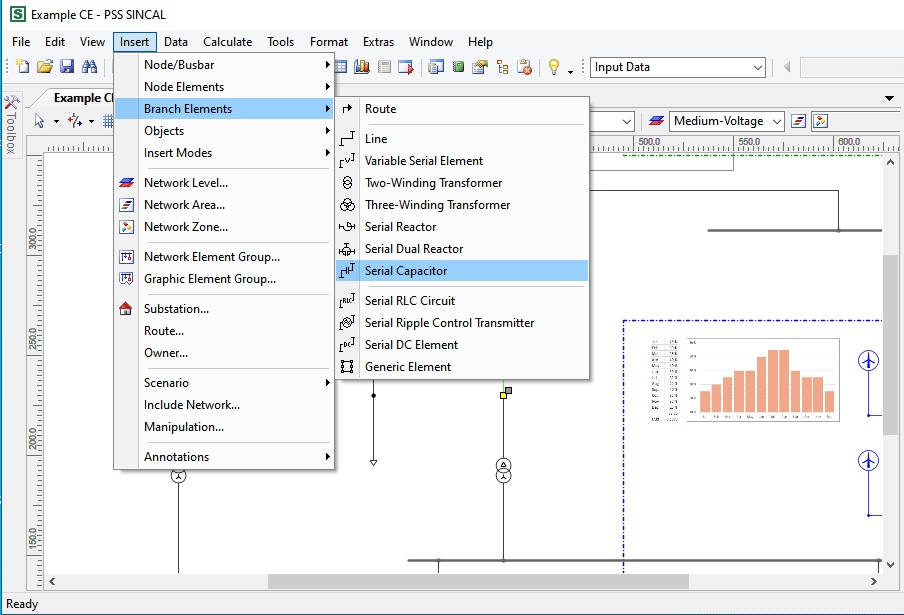
https://www.youtube.com/playlist?list=PLJExit9rQ0EqWE5FfR_IVVVBv6j50DckY
PSS® SINCAL Platform 19.5
Face-to-face / Online
Trainer: Dr. Saeed Roostaee (Profile)
- Power System Automation communication protocol
- Open Protocol
- Introduction to DNP3 protocol
- Why DNP
- DNP3 overview
- DNP Stack
- DNP3 messages
- DNP3 Application Layer
- Transport Function
- Link Layer
- DNP3 protocol simulation
- Practical section with DNP3 protocol
- DNP Protocol translator
Online Sections:
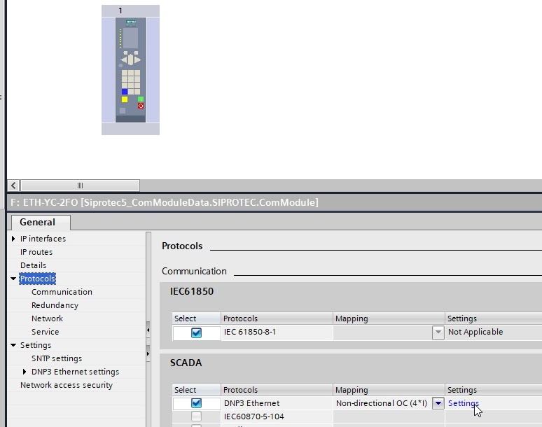
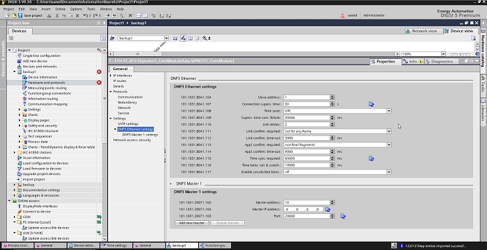
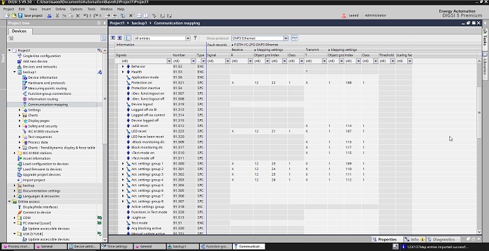
Configuration in DIGSI 5 SIPROTEC 5: basic DNP3 settings of TIM/CP (Device Configuration); configuration of a DNP3 connection in DIGSI 5; SIPROTEC 5 time synchronization in the DNP3 protocol; transferring analog values, counter values, and Boolean values time stamping, and event-buffering; Transferring Commands and Setpoint; peer-to-peer communication; serial & IP/Ethernet-based communication;
Exercise for simple system configurations with Ethernet-based networks …

- Type: Online-Training
- Trainer: Dr. Saeed Roostaee (Profile)
- Language: En
- Duration: 3 days
- Dates and Registration: End of this post
SAS introduction:
- Substation Automation Structure
- Conventional Control & Protection
- Modern Substation Automation (SA)
- Implementation of Intelligent Technology
- Intelligent SA Architecture
- Digital Substation
- Monitoring via IEDs for Protection
- Block diagram for a typical numerical relay
- Analogue to digital conversion
- Digital Phasor Measurement
Communication Introduction
- Parallel interface example
- Serial interface example
- Communication Medium
- Frame
- Baud rate
- Baud rate effect on frames
- Medium Access Methods
- Industrial Communication Protocols
- Profi-bus
- Profi-net
- RS232
- SPI
- Ethernet
- Parity & CRC
- Basic Data Types in Power System
- Info Identification for IEC 60870-5-103
OSI model
- Physical Layer
- Data link Layer
- Network Layer
- Application Layer
- Ethernet Addressing
- Frame and Packet
- TCP and UDP
- TCP/IP & its application in SAS
- UDP/IP & its application in SAS
IEC 60870
- What is IEC 60870-5?
- Introduction in IEC 60870-5 protocol-101/104 protocol
- Standard Protocols based on IEC 60870-5
- IEC 60870-5-101 features
- IEC 101 Telegram structure
- Cause of transmission
- ASDU (Application Service Data Unit)
- ASDU type identification
- Quality description
- IEC 60870-5-101 physical layer
- IEC 60870-5-101 Data Link layer
- IEC 60870-5-101 Application layer
- IEC 60870-5-104 stack layer
- Installation guidelines and configuring aids
- Network examples and network configuring
- IEC 60870-5 Configuration in DIGSI 5
- configuration of an IEC connection
- time synchronization in IEC 60870-5 protocol
IEC 60870-104 simulation
- IEC104 slave device
- IEC 60870 – 5 – 104 Signals Type
- COMMAND – IEC 60870-5-101
- Command IEC 60870 – 5 – 104
- Master IEC 60870 – 5 – 104 Protocol Test
- Timeout
- DEVICE IEC 60870 – 5 – 104 SLAVE PROPERTIES
IEC 60870-104 config in SIPROTEC 5
- SIPROTEC 5 Hardware
- General Settings
- User interface
- SIPROTEC 5 Config Procedure
- IEC 60870-104 config
- IEC 60870-104 simulation
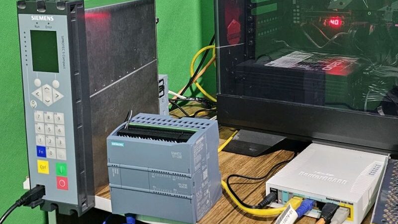
Dates and Registration
| Date | Status |
| 22-24 March 2024 | Full (no seats available) |
| 6-8 May 2024 | Open (EUR 1100) |
| 18-20 June 2024 | Full (no seats available) |
| 16-18 Aug 2024 | Open (EUR 1400) |
| 14-16 Nov 2024 | Open (EUR 1400) |
IEC 60870-5 is an international standard that defines communication protocols and data exchange formats for telecontrol systems used in the monitoring and control of industrial processes and power systems. Specifically, IEC 60870-5 specifies the protocols for interfacing remote terminal units (RTUs) and control centers in supervisory control and data acquisition (SCADA) systems. The standard outlines communication profiles for telecontrol equipment, detailing formats for information exchange, data frames, and error handling mechanisms to facilitate reliable and efficient communication between devices in industrial automation and power system applications. Adherence to the IEC 60870-5 standard helps ensure compatibility, interoperability, and seamless integration of equipment from various suppliers in SCADA systems, contributing to operational reliability and efficiency.
features:
IEC 60870-5-101 is a specific part of the IEC 60870-5 standard that defines a balanced communication protocol for the telecontrol of electrical substations. Some features of IEC 60870-5-101 include a master/slave communication model, support for serial interfaces (such as RS-232 or RS-485), structured data frame formats for transmitting control commands and telemetry data, error checking mechanisms for data integrity, and application profiles tailored for the telecontrol of electricity substations. This protocol is widely used in SCADA systems for monitoring and controlling substations, providing a reliable and standardized communication method for efficient operation and maintenance of power distribution networks.
In IEC 60870, the ASDU (Application Service Data Unit) is a fundamental concept used to structure and exchange information between devices in SCADA systems. The ASDU serves as a standardized format for encapsulating control commands, measurements, status information, and other data relevant to supervisory control and monitoring. It is designed to ensure interoperability and consistency in communication between remote terminal units (RTUs) and control centers, allowing for efficient data exchange and reliable operation in industrial automation and power system applications. By defining the structure and content of the ASDU, IEC 60870 provides a common framework for transmitting and interpreting data within the telecontrol systems, enhancing system performance and reliability.
The physical layer of IEC 60870-5-101 standard specifies the requirements for the physical connection and communication characteristics between devices in a telecontrol system. It defines parameters such as voltage levels, signaling rates, modulation techniques, and electrical interfaces to ensure reliable data transmission over serial communication links like RS-232 or RS-485. By standardizing the physical layer, IEC 60870-5-101 facilitates interoperability and compatibility between different devices and systems, enabling efficient and secure telecontrol communication within power grids and other industrial environments.
In DIGSI 5, the configuration of IEC 60870-5 protocols involves defining the communication parameters, addressing, and mapping of data objects between devices in a telecontrol system. Users can set up communication links, configure station addresses, define data types and structure, and map data points between remote terminal units (RTUs) and control centers using the IEC 60870-5 standard. DIGSI 5 offers a user-friendly interface with tools for configuring the IEC 60870-5 protocols, enabling users to create reliable and efficient telecontrol systems compliant with the standard. Through the configuration process in DIGSI 5, users can establish seamless communication and data exchange between different elements of the telecontrol system, facilitating automation and monitoring functionalities in various industries.
Time synchronization is a critical aspect of the IEC 60870-5 protocol, especially in systems where precise timing is essential for coordinating control actions and data exchange between devices. The protocol includes provisions for time synchronization through mechanisms like the Time-of-Day (ToD) information exchange between master and slave devices, ensuring that all elements in the system are operating on a synchronized clock. By maintaining accurate time synchronization, IEC 60870-5 protocol helps to improve the reliability, efficiency, and coordination of telecontrol systems, which are vital for applications in power system automation, industrial processes, and other sectors where time-critical operations are involved.
Simulating IEC 60870-104 protocols is important for testing and validating telecontrol systems before deployment. Using simulation tools, users can emulate the behavior of IEC 60870-104 devices, simulate different scenarios, and assess the system’s performance under various conditions. This allows for thorough testing of communication links, data exchange, and error handling mechanisms, ensuring that the telecontrol system functions as intended and meets operational requirements. By conducting simulations with IEC 60870-104 protocol, users can identify potential issues, optimize system configurations, and enhance the reliability and efficiency of telecontrol systems in critical infrastructure applications.

- Online+ Pre-recorded Training
- 3-5 April 2024
- 22-24 March 2024
- Pre-requisite training: DIGSI 4, DIGSI 5, IEC61850
- Language: English
- Supporting Files
- Trainer: Dr. Saeed Roostaee (Profile)
- Limited seats available
- Registration link: expired
Module I: Substation Automation System
- Substation Automation System-an overview
- Introduction to Communication
- Network Theory
- Fundamentals of Communication Via Ethernet Various Topologies in SIEMENS SAS
Module II: Bay Level Engineering (IEC 61850 and Modbus)
- Add SIPROTEC 4 6MD66 device
- Setting the Network Parameters
- 6MD configuration
- IEC61850 Configuration
- Updating ICD – Files
Module III: Station Level Engineering SICAM PAS
- Introduction to SICAM PAS Automation System
- SICAM PAS Tasks
- Fields of Application
- SICAM PAS Features
- Scalability – Software and Hardware Configuration for Small to Large Applications
- Basic Package “ Full Server”
- SICAM PAS Packages (IEC 61850, Profibus FMS (SICAM/SIPROTEC specified protocols), IEC 60870-5-103, DNP V3.00, Profibus DP, Modbus, ILSA (Internal LSA protocol, OPC-Client, Automation CFC)
- Licensing
- Licensing With Feature Enabler
- IEC 61850 Services in IEDs and SICAM PAS
- SICAM PAS Configuration (Working with Project Databases, Creating a New Database, Adding and Managing Systems, Adding an Application (IEC 61850 Client), Importing a SCD file, Updating One or Several Device(s), Adding ModbusApplication, Parameterizing ModbusApplication, Added EMA90 ModbusMap, Defining the Device Template (ModbusMap), Adding IEC 60870-5-101 Slave Application, Inserting the Control Center of IEC 60870-5-101 Slave, Inserting the SNMP Application, Monitoring IEC 61850 IEDs Connection Status With SNMP, Inserting a PASCC Application to Full Server System, Inserting Control Center to PASCC Application, Inserting a PASCC to a New System (DIP)
- Creating a CFC file
- Human-Machine Control Center Mapping, Exporting of HMI1 Interface
- Normalization
- Create a Normalization Template
- Scaling a measured value
- Assignment of normalization in Mapping
- Archiving Configured Project, Un-archiving Project
- SICAM PAS Value Viewer
- Control function
- Testing data
- ValueViewer: Communication diagnostics
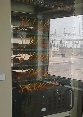
Module IV: SICAM SCC
- Export of HMI information from SICAM PAS
- Check the content of a PXD file
- Introduction to SICAM PASCC Control Center
- SICAM PASCC Control Center ‐ Overview
- SIMATIC WinCC
- SICAM PASCC Components
- SICAM PASCC Communication
- SICAM PAS Wizard
- WinCC Explorer
- Graphic Objects Library
- Switchgear Objects
- Schwitchgear Objects – Styles and States
- Alarm Logging – Message List
- Control & Monitoring
- WinCC & PASCC Licensing
- SIMATIC WinCC / SICAM PASCC Installation Steps
- Transfer The License Keys
- SIMATIC WinCC / SICAM PASCC Time Synchronization & NTP
- SICAM PASCC Starting The WinCC/PASCC Software
- SICAM PASCC Creating/ Opening a New Project
- SICAM PASCC Defining The Computer Properties General Tab, Startup Tab, Parameters Tab, Graphics Runtime Tab
- Adding a Communication Driver
- Connection Properties
- Entering the IP Address of SICAM PAS Servers
- Error Log File of SICAM PAS Wizard
- Select the Right SICAM PAS Protocol Suite
- Set PAS IP Connection
- Importing of the Sample Pilot Project .pxd File
- Checking Structure Tags of a New Project
- Structure Tag Elements
- Symbol Library
- SICAM Administrative Internal Tags
- Schwitchgear Objects – Tag Connection
- Design of Graphical Objects
- Switchgear Objects – Sychro-Check
- Alarm Logging – Events & Alarms
- Alarm Logging – Message Queue & Mes Ack Tags
- Tag Logging – Measured Values
- WinCC Horn Tools– Sound File
- Tag Logging – Archive Configuration
- Trends Picture
- Topological coloring
- Event List
- Alarm List
- Protection Message List
- Horn, Alarm Acknowledgment
- Creating an Event List in the Graphics Designer
- User Administrator
- Login via button
- Report Designer – Print Job
- Project Archive, Duplicator
- Bay Blocking
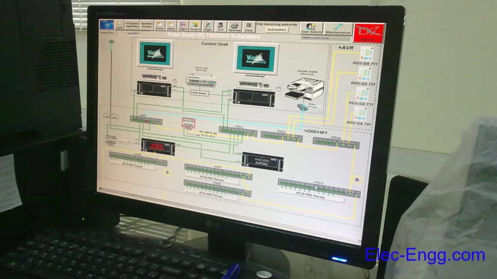

- SIEMENS 7UT6X RELAY SETTING
SIEMENS 7UT6X DIFFERENTIAL SLOPE CURVE
SIEMENS 7UT6X SLOPE POINTS CALCULATION
SIEMENS 7UT6X PROTECTING TRANSFORMERS FROM INTERNAL FAULTS
SIEMENS 7UT6X VECTOR GROUP COMPENSATION / CORRECTION FACTOR - SIEMENS 7UT8X RELAY SETTING
SIEMENS 7UT8X DIFFERENTIAL SLOPE CURVE
SIEMENS 7UT8X SLOPE POINTS CALCULATION
SIEMENS 7UT8X PROTECTING TRANSFORMERS FROM INTERNAL FAULTS
SIEMENS 7UT8X VECTOR GROUP COMPENSATION / CORRECTION FACTOR - MICOM P6XX RELAY SETTING
MICOM P6XX DIFFERENTIAL SLOPE CURVE
MICOM P6XX SLOPE POINTS CALCULATION
MICOM P6XX PROTECTING TRANSFORMERS FROM INTERNAL FAULTS
MICOM P6XX VECTOR GROUP COMPENSATION / CORRECTION FACTOR - ABB RET615 RELAY SETTING
ABB RET615 DIFFERENTIAL SLOPE CURVE
ABB RET615 SLOPE POINTS CALCULATION
ABB RET615 PROTECTING TRANSFORMERS FROM INTERNAL FAULTS
ABB RET615 VECTOR GROUP COMPENSATION / CORRECTION FACTOR
The Transformer Protection Training training course explains how the Differential protection algorithm works.


- Pre-recorded videos with lifetime access
- Trainer: Dr. Saeed Roostaee (Profile)
- Course creation: April 2024
- Last update: April 2024
Prerequisite:
Course Content:
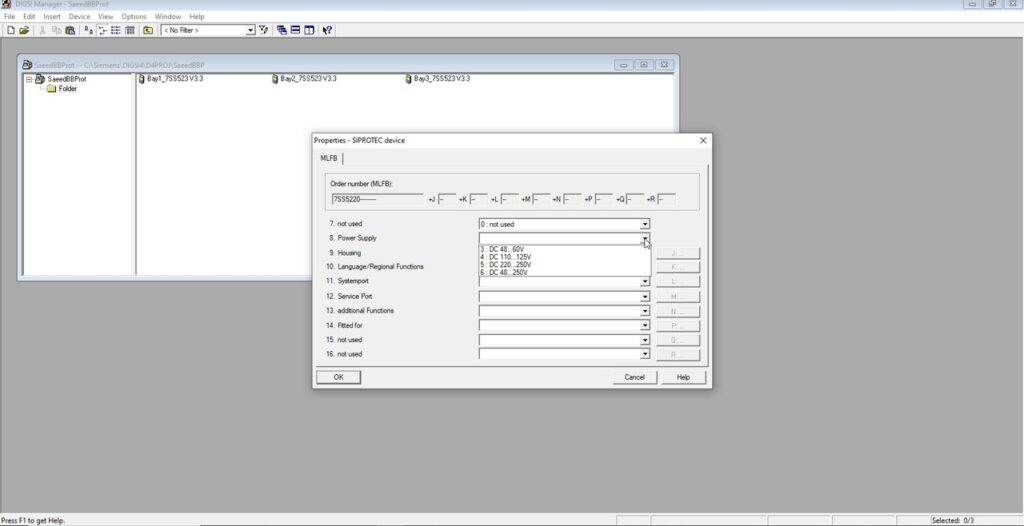
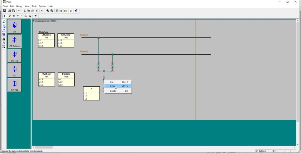

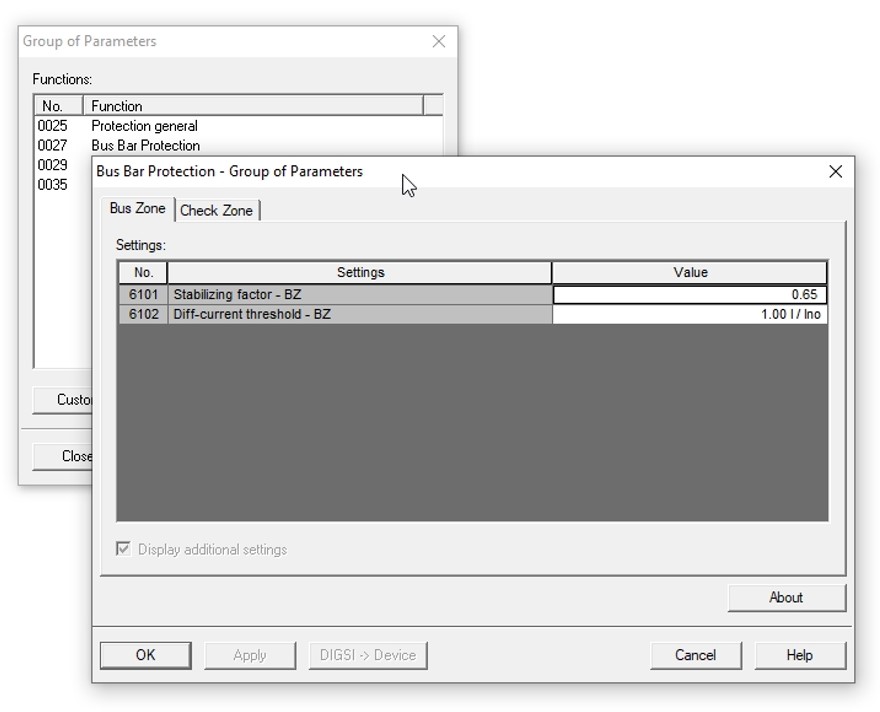
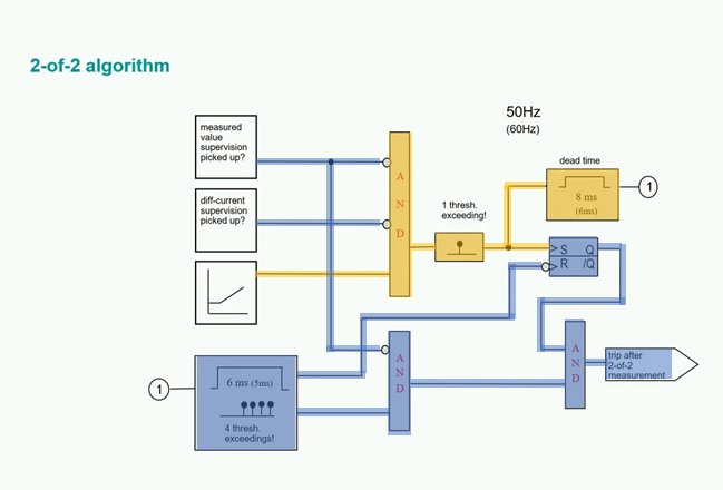
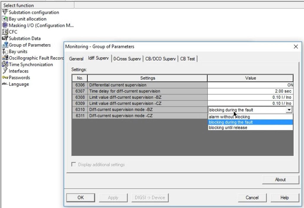
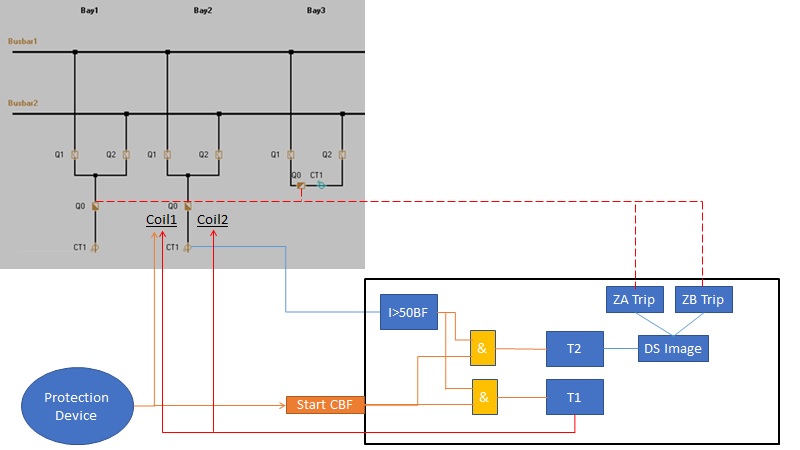
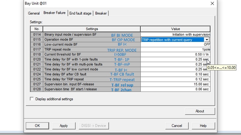
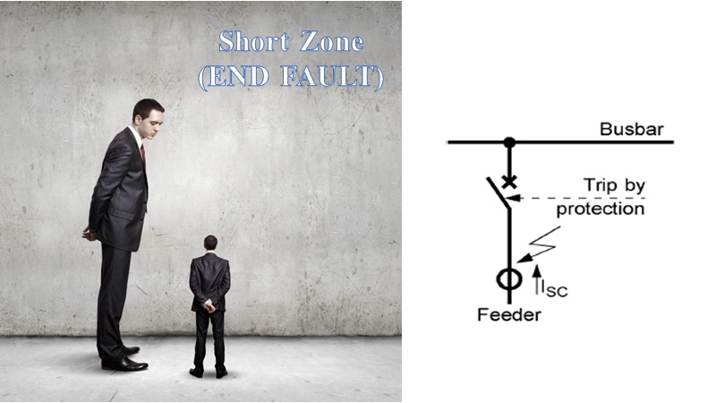
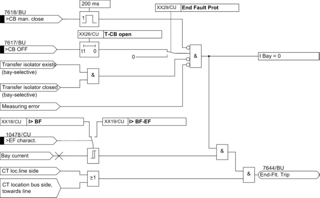

- Pre-recorded videos with lifetime access
- Trainer: Dr. Saeed Roostaee (Profile)
- Course creation: April 2024
- Last update: April 2024
Prerequisite:
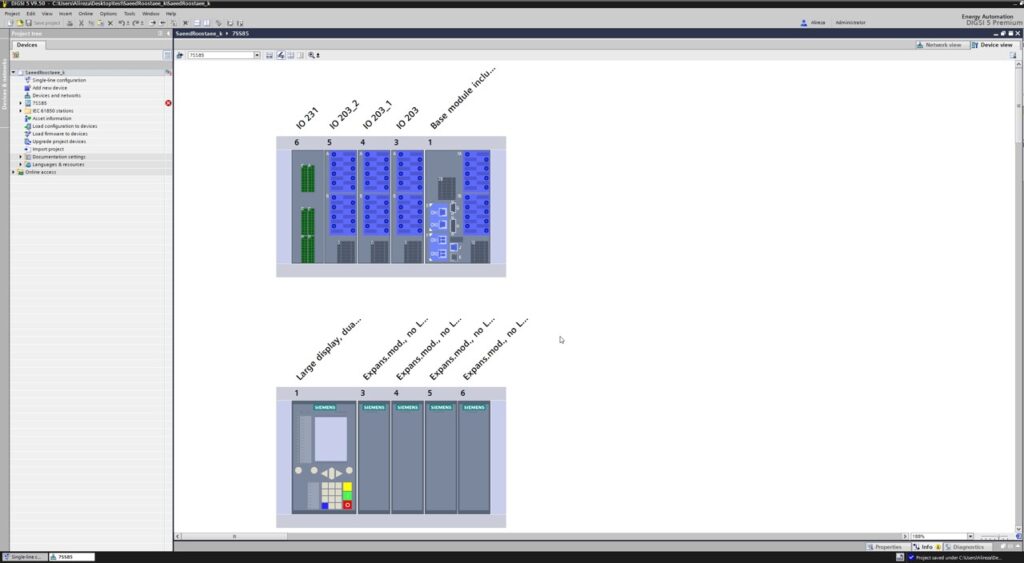
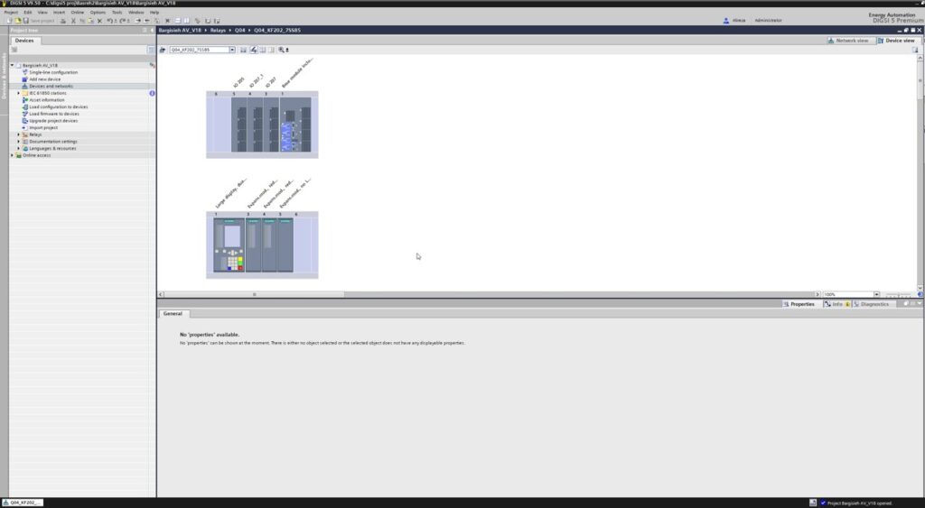
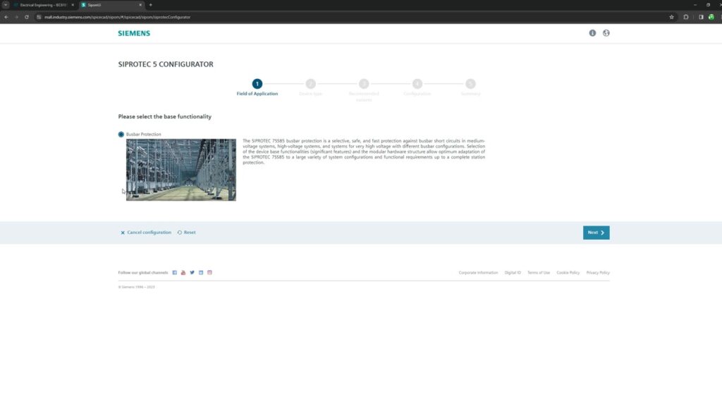
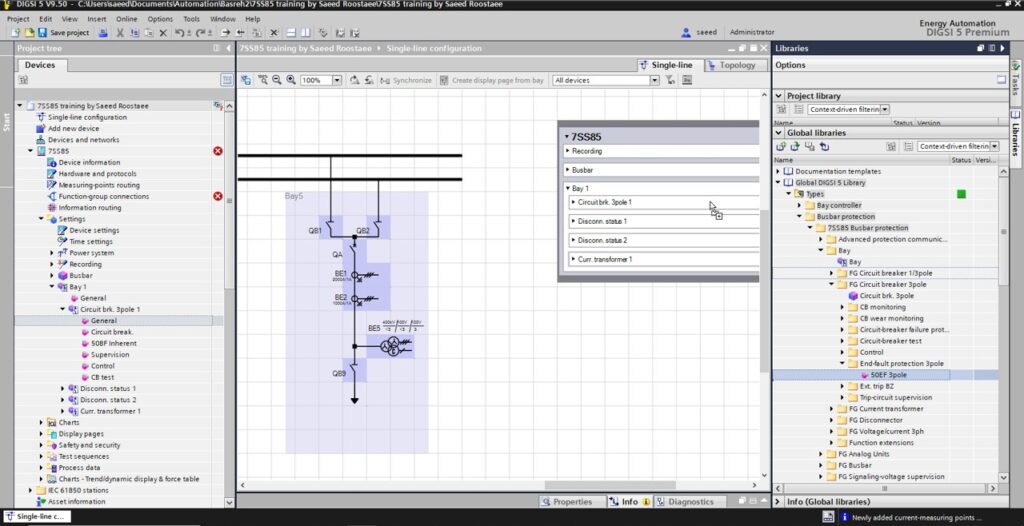
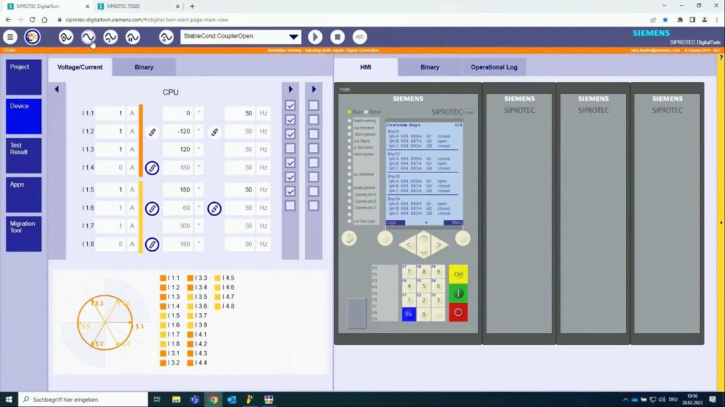
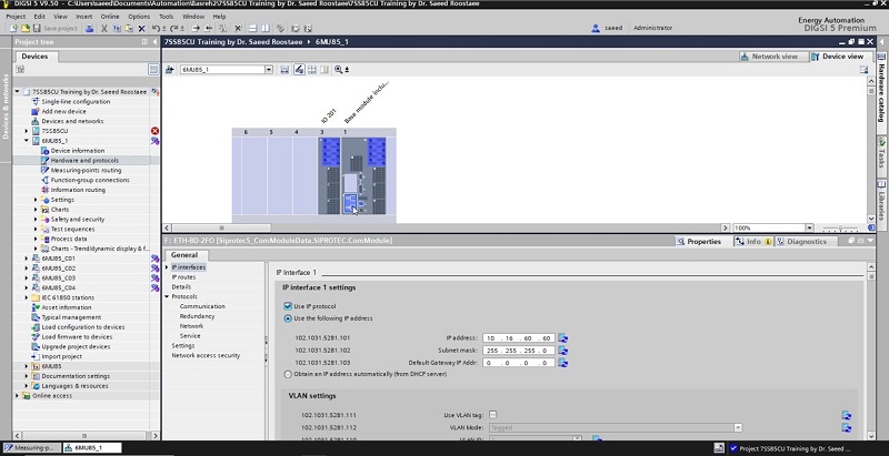

7SS85 Busbar protection